Fuel Tank Fuel Pump Module Replacement (AWD)
| Fuel Tank Fuel Pump Module Replacement (AWD) |
Special Tools
EN-48279 Main Fuel Pump Locking Ring Remover/InstallerFor equivalent regional tools, refer to Special Tools .
| Removal Procedure |
| 1. |
Open hood.
|
|
| 2. |
Turn the ignition OFF. |
|||||||||||||||
| 3. |
Disconnect the negative battery cable. Refer to
Battery Negative Cable Disconnection and Connection
.
|
|
| 4. |
Relieve the fuel system pressure. Refer to
Fuel Pressure Relief
.
|
|
| 5. |
Raise and support the vehicle. Refer to
Lifting and Jacking the Vehicle
.
|
|
| 6. |
Drain the fuel tank. Refer to
Fuel Tank Draining
.
|
|
| 7. |
Remove the propeller shaft. Refer to
Propeller Shaft Replacement
.
|
|
| 8. |
Disconnect the fuel tank filler vent pipe quick connector (1) from the fuel tank filler vent pipe (2). Refer to Plastic Collar Quick Connect Fitting Service . 
|
|||||||||
| 9. |
Remove the fuel tank filler hose fastener (3).
|
|
| 10. |
Remove the fuel tank filler hose (4).
|
|
| 11. |
Disconnect the evaporative emission front pipe quick connector from the evaporative emission front pipe (1). Refer to
Plastic Collar Quick Connect Fitting Service
.

|
|
| 12. |
Disconnect the fuel feed front pipe quick connector from the fuel feed front pipe (2). Refer to
Plastic Collar Quick Connect Fitting Service
.
|
|
| 13. |
Loosen both front fasteners of the rear axle. Lower the rear axle to 20 mm (0.8 in) . Refer to Rear Axle Replacement (G96) Rear Axle Replacement (Without G96) . |
|||||||
| 14. |
Position a suitable hydraulic lift below the fuel tank.
|
|
| 15. |
Remove both fuel tank strap fasteners (1).

|
|
| 16. |
Remove both fuel tank straps from the fuel tank (2).
|
|
| 17. |
With the aid of an assistant, lower the hydraulic lift to remove the fuel tank from the vehicle.
|
|
| 18. |
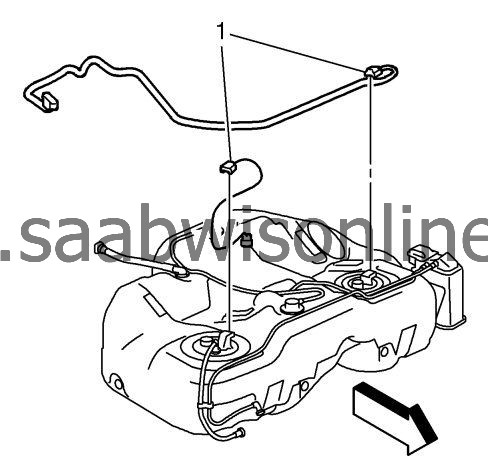
Disconnect both fuel tank fuel pump module wiring harness connectors (1) from the fuel tank fuel pump modules.

|
|
| 19. |
Remove the fuel tank from the hydraulic lift.
|
|
| Disassembly Procedure |
| 1. |
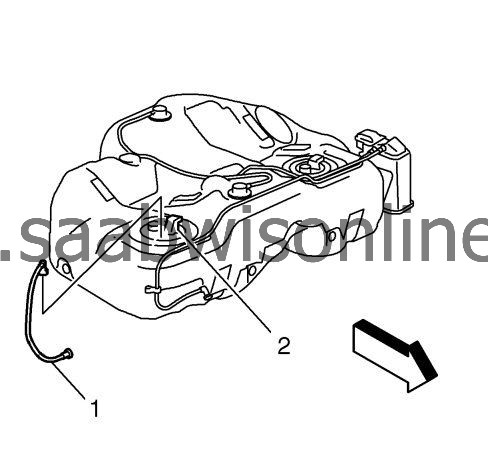
Disconnect the fuel feed pipe (1) from the fuel tank and the fuel tank fuel pump module (2). Refer to
Plastic Collar Quick Connect Fitting Service
.

|
|
| 3. |
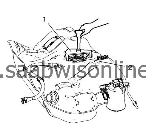
Using the
EN-48279
remover / installer and a long breaker-bar, rotate the fuel pump module lock rings (1) in a counterclockwise direction in order to unlock the fuel pump module lock rings.

|
|
| 4. |
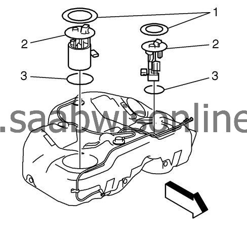
Remove the fuel tank fuel pump modules (2).
|
|
| 5. |
Remove and discard the fuel tank fuel pump module O-ring seals (3). |
|||||||
| Assembly Procedure |
| 1. |
Install NEW fuel tank fuel pump module O-ring seals (3).

|
|
| 2. |
Install the fuel tank fuel pump modules (2).
|
|
| 3. |
Install the fuel pump module lock rings (1).
|
|
| 4. |
Using the EN-48279 remover/installer and a long breaker-bar, rotate the fuel pump module lock ring (1) in a clockwise direction in order to lock the fuel pump module lock ring (2). 
|
|||||||
| 5. |
Connect the fuel feed pipe (1) to the fuel tank and the fuel tank fuel pump module (2). Refer to
Plastic Collar Quick Connect Fitting Service
.

|
|
| Installation Procedure |
Refer to Fastener Caution .

| 1. |
Install the fuel tank to the hydraulic lift.
|
|
| 2. |
Connect the fuel tank fuel pump module wiring harness connectors (1) to the fuel tank fuel pump modules.
|
|
| 3. |
With the aid of an assistant, install the fuel tank to the vehicle.

|
|
| 4. |
Install both fuel tank straps to the fuel tank (2).
|
|
| 5. |
Install both fuel tank strap fasteners (1).
|
|
| 6. |
Remove the hydraulic lift from the fuel tank.
|
|
| 7. |
Install both front fasteners of the rear axle. Refer to
Rear Axle Replacement (G96)
Rear Axle Replacement (Without G96)
.
|
|
| 8. |
Connect the fuel feed front pipe quick connector to the fuel feed front pipe (2). Refer to
Plastic Collar Quick Connect Fitting Service
.

|
|
| 9. |
Connect the evaporative emission front pipe quick connector to the evaporative emission front pipe (1). Refer to
Plastic Collar Quick Connect Fitting Service
.
|
|
| 10. |
Install the fuel tank filler hose (4).

|
|
| 11. |
Install the fuel tank filler hose fastener (3) and tighten to
4 Nm (35 lb in)
.
|
|
| 12. |
Connect the fuel tank filler vent pipe quick connector (1) to the fuel tank filler vent pipe (2). Refer to
Plastic Collar Quick Connect Fitting Service
.
|
|
| 13. |
Install the propeller shaft. Refer to
Propeller Shaft Replacement
.
|
|
| 14. |
Connect the negative battery cable. Refer to
Battery Negative Cable Disconnection and Connection
.
|
|
| 15. |
Close hood.
|
|

 Warning

