Component Connector End Views
| Component Connector End Views |
Connector Part Information
|
||||||||||||
Terminal Part Information
|
||||||||||||
A10 Inside Rearview Mirror (DD8)
| Pin | Wire Color | Circuit No. | Operation |
|
1
|
0.35 GN/WH
|
24
|
Backup Lamp Supply Voltage (without TQ5)
|
|
0.5 GN
|
5060
|
Low Speed GMLAN Serial Data (TQ5)
|
|
|
2
|
0.5 RD/GY
|
2840
|
Battery Positive Voltage
|
|
3
|
0.5 GN/WH
|
2514
|
Keypad Signal (UE1)
|
|
4
|
0.5 GN/BK
|
2515
|
Keypad Supply Voltage (UE1)
|
|
5
|
0.5 BK/WH
|
2051
|
Signal Ground (without UVL or UVT or CE1or TTW)
|
|
0.5 BK/WH
|
2251
|
Signal Ground (UVL or UVT or CE1 with TTW)
|
|
|
6
|
0.5 YE/VT
|
2516
|
Keypad Green LED (UE1)
|
|
7
|
0.5 BN/WH
|
2517
|
Keypad Red LED (UE1)
|
|
8
|
0.5 BK/YE
|
1691
|
Low Reference
|
|
9
|
0.5 YE/WH
|
1690
|
Automatic Day/Night Mirror Signal (DWD or DWJ)
|
|
10
|
0.5 RD/WH
|
1040
|
Battery Positive Voltage (TQ5)
|
| A11 Radio X1 |
Connector Part Information
|
|||||||||||||||||||||||||||||||||||||||||||||||||||
Terminal Part Information
|
|||||||||||||||||||||||||||||||||||||||||||||||||||
A11 Radio X1
| Pin | Wire Color | Circuit No. | Operation |
|
1
|
0.35 BARE
|
1574
|
Rear Audio Drain Wire (ULD)
|
|
2
|
0.35 YE
|
7459
|
Integrated Center Stack Serial Data Low (UAG or UDT)
|
|
3
|
0.35 BARE
|
7460
|
Integrated Center Stack Serial Data Shield (UAG or UDT)
|
|
4
|
0.5 GN/BU
|
6761
|
Center Channel Low Level Audio Signal (-) (UQS)
|
|
5
|
0.5 WH/BK
|
6762
|
Subwoofer Low Level Audio (-) (UQS)
|
|
6
|
0.5 BK/YE
|
659
|
Low Reference (UE1 or UPH or UPJ)
|
|
7
|
0.35 GY/WH
|
388
|
Remote Radio Right Audio Signal (2) (UBT)
|
|
8
|
0.35 BN/BK
|
372
|
Remote Radio Audio (-) (UBT)
|
|
9
|
0.35 BARE
|
1573
|
Front Audio Drain Wire (UBT)
|
|
10
|
0.35 GN
|
3376
|
Right Auxiliary Audio Signal (3) (KTA)
|
|
0.35 GN
|
5841
|
Right Auxiliary Audio Signal (2) (without KTA)
|
|
|
11
|
0.35 BU
|
2060
|
Auxiliary Detection Signal
|
|
12
|
0.35 YE/VT
|
3352
|
Rear Seat Audio Common Signal (ULD)
|
|
13
|
0.35 GY/GN
|
3291
|
Integrated Center Stack Wake Up Signal (UAG or UDT)
|
|
14
|
0.5 GN
|
5060
|
Low Speed GMLAN Serial Data
|
|
15
|
-
|
-
|
Not used
|
|
16
|
0.35 VT
|
7458
|
Center Integrated Center Stack Serial Data High (UAG or UDT)
|
|
17
|
0.35 BARE
|
5842
|
Auxiliary Audio Screen (2) (without KTA)
|
|
18
|
0.5 VT/BU
|
6760
|
Center Channel Low Level Audio Signal (UQS with UXY or UXG or UYS or UYT or UYU or UYV or UYW or UYX or UYZ or U44)
|
|
19
|
0.5 BU/VT
|
6763
|
Subwoofer Low Level Audio Signal (UQS with UXY or UXG or UYS or UYT or UYU or UYV or UYW or UYX or UYZ or U44)
|
|
20
|
0.5 YE
|
658
|
Cellular Telephone Voice Signal (UE1 or UPH or UPJ)
|
|
21
|
0.35 GN/WH
|
368
|
Remote Radio Right Audio Signal (1) (UBT)
|
|
22
|
0.35 BN/WH
|
367
|
Remote Radio Left Audio Signal (UBT)
|
|
23
|
0.35 GN
|
3376
|
Auxiliary Audio Common Signal (3)
|
|
24
|
0.35 VT
|
3377
|
Left Auxiliary Audio Signal (3) (KTA)
|
|
0.35 GY
|
5839
|
Left Auxiliary Audio Signal (2) (without KTA)
|
|
|
25
|
0.35 WH/GY
|
5312
|
Left Rear Seat Audio Signal (ULD)
|
|
26
|
0.35 WH/GN
|
5313
|
Right Rear Seat Audio Signal (ULD)
|
|
27
|
0.35 VT
|
3290
|
Integrated Center Stack Reset Signal (UAG or UDT)
|
|
28
|
0.5 GN
|
5060
|
Low Speed GMLAN Serial Data
|
|
29-30
|
-
|
-
|
Not used
|
|
31
|
1 YE/BK
|
117
|
Right Front Speaker Signal (-) (1) (U63 or U65)
|
|
0.5 BU/BN
|
1546
|
Front Low Level Audio (-) (UQS)
|
|
|
32
|
0.5 BN/BU
|
1947
|
Left Front Low Level Audio (-) (UQS)
|
|
1 BN/BU
|
118
|
Left Front Speaker Signal (-) (1) (U63 or U65)
|
|
|
33
|
0.5 BU/BK
|
1946
|
Right Rear Low Level Audio (-) (UQS)
|
|
1 BU/BK
|
115
|
Right Rear Speaker Signal (-) (U63 or U65)
|
|
|
34
|
0.5 BN/VT
|
1999
|
Left Rear Low Level Audio (-) (UQS)
|
|
1 GN/BK
|
116
|
Left Rear Speaker Signal (-) (U63 or U65)
|
|
|
35
|
0.35 YE
|
5169
|
Mid Speed GMLAN Serial Data (+)
|
|
36
|
0.35 WH
|
5170
|
Mid Speed GMLAN Serial Data (-)
|
|
37
|
0.5 VT/BU
|
6978
|
Amplifier Control (UQS)
|
|
38
|
2.5 BK
|
1750
|
Ground
|
|
39
|
0.5 YE
|
512
|
Right Front Low Level Audio Signal (UQS)
|
|
1 YE
|
200
|
Right Front Speaker (+) (1)) (U63 or U65)
|
|
|
40
|
0.5 BU
|
511
|
Left Front Low Level Audio Signal (UQS)
|
|
1 BU
|
201
|
Left Front Speaker (+) (1)) (U63 or U65)
|
|
|
41
|
0.5 BN/WH
|
546
|
Right Rear Low Level Audio Signal (UQS)
|
|
1 WH
|
46
|
Right Rear Speaker (+)) (U63 or U65)
|
|
|
42
|
1 GN
|
199
|
Left Rear Speaker (+)) (U63 or U65)
|
|
0.5 GN/BK
|
599
|
Left Rear Low Level Audio Signal (UQS)
|
|
|
43
|
0.75 GN/YE
|
7066
|
Entertainment Remote Enable Signal
|
|
44
|
2.5 RD/GN
|
40
|
Battery Positive Voltage
|
| A11 Radio X3 (UWG) |
Connector Part Information
|
||||||||||||
Terminal Part Information
|
||||||||||||
A11 Radio X3 (UWG)
| Pin | Wire Color | Circuit No. | Operation |
|
1
|
0.35 BU/YE
|
5826
|
Left DVD Audio Signal (+)
|
|
2
|
0.35 VT
|
6979
|
DVD Audio Common
|
|
3
|
0.35 YE
|
2059
|
Left Auxiliary Audio Signal (1)
|
|
4
|
0.35 GY/BN
|
5844
|
Video Bright Control
|
|
5
|
0.35 VT/BK
|
5845
|
Video Module Signal
|
|
6
|
0.5 GN/BU
|
5831
|
Remote Infra Red Signal (+)
|
|
7
|
0.35 YE
|
2056
|
Auxiliary Video High Signal
|
|
8
|
0.35 BU
|
7396
|
DVD Video Signal 2 (+)
|
|
9
|
0.35 BARE
|
6976
|
DVD Video Drain Wire
|
|
10
|
0.35 GN
|
6975
|
DVD Video Signal (+)
|
|
11
|
0.35 WH/BU
|
5828
|
Right DVD Audio Signal (+)
|
|
12
|
0.35 BARE
|
6980
|
DVD Audio Shield
|
|
13
|
0.35 WH
|
2058
|
Right Auxiliary Audio Signal (1)
|
|
14
|
0.35 BARE
|
5843
|
Auxiliary Audio Common Signal
|
|
15
|
0.35 WH/GN
|
7395
|
Video Mode 2 Signal
|
|
16
|
0.5 WH/YE
|
5830
|
Remote Infra Red Signal (-)
|
|
17
|
0.35 BARE
|
2057
|
Auxiliary Video Low Signal
|
|
18
|
0.35 WH
|
7394
|
DVD Video Signal 2 (-)
|
|
19
|
0.35 BARE
|
5818
|
Video Drain Wire
|
|
20
|
0.35 BN
|
5335
|
DVD Video Signal (-)
|
| A11 Radio X4 |
Connector Part Information
|
||||||||||||
Terminal Part Information
|
||||||||||||
A11 Radio X4
| Pin | Wire Color | Circuit No. | Operation |
|
1-4
|
-
|
-
|
Not used
|
|
5
|
0.5 GY/YE
|
6972
|
Camera Signal #2 + (UVC)
|
|
6
|
0.5 BU
|
655
|
Cellular Telephone Microphone Signal (UXY or UXG or UYS or UYT or UYU or UYV or UYW or UYX or UYZ or U44 without UPH or UPJ or UE1)
|
|
6
|
0.5 GY/YE
|
5149
|
Voice Recognition Audio Signal (UE1 or UPH or UPJ with UXY or UXG or UYS or UYT or UYU or UYV or UYW or UYX or UYZ or U44)
|
|
7
|
-
|
-
|
Not used
|
|
8
|
0.35 BARE
|
3368
|
Touch Screen Display Drain Wire (UDT)
|
|
9
|
0.35 GY
|
3369
|
Touch Screen Display Signal (+) (UDT)
|
|
10
|
0.5 BN/GN
|
3364
|
Navigation Display Reset Signal (UDT)
|
|
11-14
|
-
|
-
|
Not used
|
|
15
|
0.5 WH/BU
|
6973
|
Camera Signal #2 (UVC)
|
|
16
|
0.5 BK/GY
|
5152
|
Low Reference (UE1 or UPH or UPJ with UXY or UXG or UYS or UYT or UYU or UYV or UYW or UYX or UYZ or U44)
|
|
0.5 BARE
|
654
|
Low Reference (UXY or UXG or UYS or UYT or UYU or UYV or UYW or UYX or UYZ or U44 without UPH or UPJ or UE1)
|
|
|
17-18
|
-
|
-
|
Not used
|
|
19
|
0.35 VT
|
3370
|
Touch Screen Display Signal (-) (UDT)
|
|
20
|
0.5 GY
|
1903
|
AAS Wheel Speed Sensor Signal Left Front (UXY or UXG or UYS or UYT or UYU or UYV or UYW or UYX or UYZ or U44)
|
| A12 Digital Radio Receiver Control Module (UBT) |

Connector Part Information
|
||||||||||||
Terminal Part Information
|
||||||||||||
A12 Digital Radio Receiver Control Module (UBT)
| Pin | Wire Color | Circuit No. | Operation |
|
1
|
-
|
-
|
Not used
|
|
2
|
0.35 YE
|
5169
|
Mid Speed GMLAN Serial Data (+) (KTA)
|
|
3
|
0.35 YE
|
5169
|
Mid Speed GMLAN Serial Data (+)
|
|
4
|
0.75 RD/GN
|
3140
|
Battery Positive Voltage
|
|
5
|
0.35 BARE
|
1573
|
Front Audio Drain Wire
|
|
6
|
0.35 BN/WH
|
367
|
Remote Radio Left Audio Signal
|
|
7
|
0.35 BN/BK
|
372
|
Remote Radio Audio (-)
|
|
8
|
0.35 GN/WH
|
368
|
Remote Radio Right Audio Signal (1)
|
|
9
|
0.35 GY/WH
|
388
|
Remote Radio Right Audio Signal (2)
|
|
11
|
0.35 WH
|
5170
|
Mid Speed GMLAN Serial Data (-) (KTA)
|
|
12
|
0.35 WH
|
5170
|
Mid Speed GMLAN Serial Data (-)
|
|
13
|
0.75 BK
|
1750
|
Ground
|
| A13 Rear Audio Control Module (UWG or ULD) |
Connector Part Information
|
||||||||||||
Terminal Part Information
|
||||||||||||
A13 Rear Audio Control Module (UWG or ULD)
| Pin | Wire Color | Circuit No. | Operation |
|
1
|
0.35 WH/GY
|
5312
|
Left Rear Seat Audio Signal
|
|
2
|
0.35 WH/GN
|
5313
|
Right Rear Seat Audio Signal
|
|
3
|
0.35 YE/VT
|
3352
|
Rear Seat Audio Common Signal
|
|
4
|
0.35 BARE
|
1574
|
Rear Audio Drain Wire
|
|
5
|
-
|
-
|
Not used
|
|
6
|
0.5 GN
|
5060
|
Low Speed GMLAN Serial Data
|
|
7
|
-
|
-
|
Not used
|
|
8
|
0.75 BK
|
1750
|
Ground
|
|
9
|
0.35 VT/BU
|
5329
|
Left Infra Red Audio Signal
|
|
10
|
0.35 WH/VT
|
5330
|
Right Infra Red Audio Signal
|
|
11
|
0.35 BU/GY
|
3360
|
Infra Red Audio Common Signal
|
|
12
|
0.35 BARE
|
5332
|
Infra Red Audio Drain Wire
|
|
13-15
|
-
|
-
|
Not used
|
|
16
|
0.75 RD/GN
|
3140
|
Battery Positive Voltage
|
| A20 Radio/HVAC Controls (UAG) |
Connector Part Information
|
||||||||||||
Terminal Part Information
|
||||||||||||
A20 Radio/HVAC Controls (UAG)
| Pin | Wire Color | Circuit No. | Operation |
|
1-6
|
-
|
-
|
Not used
|
|
7
|
0.5 GN/BU
|
7532
|
Linear Interconnect Network Bus 10
|
|
8
|
0.5 GN/YE
|
7531
|
Linear Interconnect Network Bus 9
|
|
9
|
-
|
-
|
Not used
|
|
10
|
0.5 RD/GN
|
3140
|
Battery Positive Voltage
|
|
11-16
|
-
|
-
|
Not used
|
|
17
|
0.5 BK
|
1750
|
Ground
|
| A20 Radio/HVAC Controls (UDT) |
Connector Part Information
|
||||||||||||
Terminal Part Information
|
||||||||||||
A20 Radio/HVAC Controls (UDT)
| Pin | Wire Color | Circuit No. | Operation |
|
1
|
0.35 VT
|
7458
|
Center Integrated Center Stack Serial Data High
|
|
2
|
0.35 YE
|
7459
|
Integrated Center Stack Serial Data Low
|
|
3
|
0.35 BARE
|
7460
|
Integrated Center Stack Serial Data Shield
|
|
4
|
0.35 GY/GN
|
3291
|
Integrated Center Stack Wake Up Signal
|
|
5-7
|
-
|
-
|
Not used
|
|
8
|
0.5 GN/YE
|
7531
|
Linear Interconnect Network Bus 9
|
|
9
|
-
|
-
|
Not used
|
|
10
|
0.5 RD/GN
|
3140
|
Battery Positive Voltage
|
|
11-14
|
-
|
-
|
Not used
|
|
15
|
0.35 VT
|
3290
|
Integrated Center Stack Reset Signal
|
|
16
|
-
|
-
|
Not used
|
|
17
|
0.5 BK
|
1750
|
Ground
|
|
18
|
-
|
-
|
Not used
|
| A23D Door Latch Assembly - Driver |
Connector Part Information
|
||||||||||||
Terminal Part Information
|
||||||||||||
A23D Door Latch Assembly - Driver
| Pin | Wire Color | Circuit No. | Operation |
|
1
|
1 BN
|
5910
|
Door Double Lock Actuator Lock Control
|
|
2
|
1 BN/YE
|
294
|
Door Lock Actuator Unlock Control
|
|
3
|
1 GY
|
5911
|
Door Lock Actuator Lock Control 2 (LHD)
|
|
1 GY
|
295
|
Door Lock Actuator Lock Control (RHD)
|
|
|
4
|
0.5 WH/VT
|
3270
|
Driver Door Lock Motor Status Control (LHD)
|
|
5
|
1 GY
|
3578
|
Driver Door Unlatch Motor Unlatch Return (LHD with ATH)
|
|
1 GY/BK
|
3579
|
Co Driver Door Unlatch Motor Unlatch Return (RHD with ATH)
|
|
|
6
|
0.5 GY
|
745
|
Left Front Door Ajar Switch Signal
|
|
7
|
0.5 WH/YE
|
3574
|
Driver Door Open Switch Signal (LHD)
|
|
0.5 GY/GN
|
3575
|
Co_Driver Door Open Switch Signal (RHD)
|
|
|
8
|
0.75 BK
|
1550
|
Ground
|
|
9
|
0.5 BU/VT
|
1124
|
Door Lock Key Switch Unlock Signal (LHD)
|
|
10
|
1 YE/GN
|
3583
|
Co Driver Door Unlatch Motor Unlatch Control (RHD with ATH)
|
|
1 VT/BU
|
6666
|
Driver Door Unlatch Motor Unlatch Control (LHD with ATH)
|
| A23LR Door Latch Assembly - Left Rear |
Connector Part Information
|
||||||||||||
Terminal Part Information
|
||||||||||||
A23LR Door Latch Assembly - Left Rear
| Pin | Wire Color | Circuit No. | Operation |
|
1
|
1 BN
|
5910
|
Door Double Lock Actuator Lock Control
|
|
2
|
1 BN/YE
|
294
|
Door Lock Actuator Unlock Control
|
|
3
|
1 GY
|
295
|
Door Double Lock Actuator Lock Control
|
|
4
|
1 BN/YE
|
294
|
Door Lock Actuator Unlock Control
|
|
5
|
0.75 BU/YE
|
3580
|
Left Rear Door Unlatch Motor Unlatch Return (ATH)
|
|
6
|
0.5 GY
|
747
|
Left Rear Door Ajar Switch Signal
|
|
6
|
0.5 GY
|
747
|
Left Rear Door Ajar Switch Signal
|
|
7
|
0.75 WH/BU
|
3266
|
Child Security Lock Motor Unlock Control
|
|
8
|
0.75 BK
|
2350
|
Ground
|
|
9
|
0.5 BN/WH
|
3269
|
Child Security Lock Motor Status Signal Left Rear
|
|
10
|
0.75 BU/WH
|
6667
|
Left Rear Door Unlatch Motor Unlatch Control (ATH)
|
| A23P Door Latch Assembly - Passenger |
Connector Part Information
|
||||||||||||
Terminal Part Information
|
||||||||||||
A23P Door Latch Assembly - Passenger
| Pin | Wire Color | Circuit No. | Operation |
|
1
|
0.5 GY
|
746
|
Right Front Door Ajar Switch Signal
|
|
2
|
0.5 WH/YE
|
3574
|
Driver Door Open Switch Signal (RHD)
|
|
0.5 GY/GN
|
3575
|
Co_Driver Door Open Switch Signal (LHD)
|
|
|
3
|
0.75 BK
|
1550
|
Ground
|
|
4
|
0.5 BU/VT
|
1124
|
Door Lock Key Switch Unlock Signal (RHD)
|
|
5
|
1 GY/BK
|
3579
|
Co Driver Door Unlatch Motor Unlatch Control (LHD with ATH)
|
|
1 VT/BU
|
6666
|
Driver Door Unlatch Motor Unlatch Control (RHD with ATH)
|
|
|
6
|
1 BN
|
5910
|
Door Double Lock Actuator Lock Control
|
|
7
|
1 BN/YE
|
294
|
Door Lock Actuator Unlock Control
|
|
8
|
1 GY
|
5911
|
Door Lock Actuator Lock Control 2 (RHD)
|
|
1 GY
|
295
|
Door Lock Actuator Lock Control (LHD)
|
|
|
9
|
0.5 WH/VT
|
3270
|
Driver Door Lock Motor Status Control (RHD)
|
|
10
|
1 GY
|
3578
|
Driver Door Unlatch Motor Unlatch Return (RHD with ATH)
|
|
10
|
1 YE/GN
|
3583
|
Co Driver Door Unlatch Motor Unlatch Return (LHD with ATH)
|
| A23RR Door Latch Assembly - Right Rear |
Connector Part Information
|
||||||||||||
Terminal Part Information
|
||||||||||||
A23RR Door Latch Assembly - Right Rear
| Pin | Wire Color | Circuit No. | Operation |
|
1
|
0.5 GY
|
748
|
Right Rear Door Ajar Switch Signal
|
|
2
|
0.75 WH/BU
|
3266
|
Child Security Lock Motor Unlock Control
|
|
3
|
0.75 BK
|
2050
|
Ground
|
|
4
|
0.5 GY/BK
|
3268
|
Child Security Lock Motor Status Signal Right Rear
|
|
5
|
0.75 GN/BK
|
6669
|
Right Rear Door Unlatch Motor Unlatch Control (ATH)
|
|
6
|
1 BN
|
5910
|
Door Double Lock Actuator Lock Control
|
|
7
|
1 BN/YE
|
294
|
Door Lock Actuator Unlock Control
|
|
8
|
1 GY
|
295
|
Door Double Lock Actuator Lock Control
|
|
9
|
1 BN/YE
|
294
|
Door Lock Actuator Unlock Control
|
|
10
|
0.75 GN/WH
|
3581
|
Right Rear Door Unlatch Motor Unlatch Return (ATH)
|
| A25A Glow Plug/Pressure Sensor Cylinder 1 Assembly (LBS) |
Connector Part Information
|
||||||||||||
Terminal Part Information
|
||||||||||||
A25A Glow Plug/Pressure Sensor Cylinder 1 Assembly (LBS)
| Pin | Wire Color | Circuit No. | Operation |
|
1
|
0.5 BN/VT
|
3457
|
Cylinder Pressure Sensor 1 Voltage Supply
|
|
2
|
0.5 VT
|
3458
|
Cylinder Pressure Sensor 1 Signal
|
|
3
|
0.5 BK/VT
|
3459
|
Cylinder Pressure Sensor 1 Low Reference
|
|
4
|
2.5 GY/BU
|
1581
|
Glow Plug Supply Voltage (1)
|
| A25B Glow Plug/Pressure Sensor Cylinder 2 Assembly (LBS) |
Connector Part Information
|
||||||||||||
Terminal Part Information
|
||||||||||||
A25B Glow Plug/Pressure Sensor Cylinder 2 Assembly (LBS)
| Pin | Wire Color | Circuit No. | Operation |
|
1
|
0.5 BN/GY
|
3460
|
Cylinder Pressure Sensor 2 Voltage Supply
|
|
2
|
0.5 GY
|
3461
|
Cylinder Pressure Sensor 2 Signal
|
|
3
|
0.5 BK/GY
|
3462
|
Cylinder Pressure Sensor 2 Low Reference
|
|
4
|
2.5 GY/BN
|
1582
|
Glow Plug Supply Voltage (2)
|
| A25C Glow Plug/Pressure Sensor Cylinder 3 Assembly (LBS) |
Connector Part Information
|
||||||||||||
Terminal Part Information
|
||||||||||||
A25C Glow Plug/Pressure Sensor Cylinder 3 Assembly (LBS)
| Pin | Wire Color | Circuit No. | Operation |
|
1
|
0.5 BN/BU
|
3463
|
Cylinder Pressure Sensor 3 Voltage Supply
|
|
2
|
0.5 BU
|
3464
|
Cylinder Pressure Sensor 3 Signal
|
|
3
|
0.5 BK/BU
|
3465
|
Cylinder Pressure Sensor 3 Low Reference
|
|
4
|
2.5 GY/GN
|
1583
|
Glow Plug Supply Voltage (3)
|
| A25D Glow Plug/Pressure Sensor Cylinder 4 Assembly (LBS) |
Connector Part Information
|
||||||||||||
Terminal Part Information
|
||||||||||||
A25D Glow Plug/Pressure Sensor Cylinder 4 Assembly (LBS)
| Pin | Wire Color | Circuit No. | Operation |
|
1
|
0.5 BN/WH
|
3466
|
Cylinder Pressure Sensor 4 Voltage Supply
|
|
2
|
0.5 WH
|
3467
|
Cylinder Pressure Sensor 4 Signal
|
|
3
|
0.5 BK/WH
|
3468
|
Cylinder Pressure Sensor 4 Low Reference
|
|
4
|
2.5 GY/YE
|
1584
|
Glow Plug Supply Voltage (4)
|
| A9A Outside Rearview Mirror - Driver |

Connector Part Information
|
||||||||||||
Terminal Part Information
|
||||||||||||
A9A Outside Rearview Mirror - Driver
| Pin | Wire Color | Circuit No. | Operation |
|
1
|
0.5 WH/YE
|
3395
|
Driver Mirror Position Sensor Left (-) Right (+) Signal (A45)
|
|
2
|
0.5 VT/BU
|
3390
|
Driver Mirror Motor Up (+) Down (-) Control
|
|
3
|
0.5 VT/RD
|
3392
|
Driver Mirror Position Sensor High Reference (A45)
|
|
4
|
0.5 BK
|
1550
|
Ground
|
|
5
|
0.5 GY/BN
|
3394
|
Driver Mirror Position Sensor Up (+) Down (-) Signal (A45)
|
|
6
|
0.75 BN/YE
|
2267
|
Mirror Heating Element Supply Voltage
|
|
7
|
0.5 BN/BK
|
3389
|
Driver Mirror Motor Right (+) Left (-) Control
|
|
8
|
0.5 YE/BN
|
3391
|
Driver Mirror Motor Common Control
|
|
9
|
0.5 GY/WH
|
3411
|
Driver Mirror Motor Fold Out Control (A45)
|
|
0.5 VT/YE
|
3409
|
Mirror Motor Fold Out Control (without A45)
|
|
|
10
|
0.5 WH/GN
|
3412
|
Driver Mirror Motor Fold In Control (A45)
|
|
0.5 WH/BN
|
3410
|
Mirror Motor Fold In Control (without A45)
|
|
|
11
|
0.5 GY/YE
|
5853
|
Driver Side Object Detection LED Signal (1) (UFT)
|
|
12
|
0.5 BK
|
1550
|
Ground (UFT)
|
|
13
|
0.5 YE/WH
|
1690
|
Automatic Day/Night Mirror Signal
|
|
14
|
0.5 BK/YE
|
1691
|
Low Reference
|
|
14
|
-
|
-
|
Not used
|
|
16
|
0.5 BU/WH
|
1314
|
Left Front Turn Signal Lamp Supply Voltage
|
|
17
|
0.5 GY/GN
|
5996
|
Driver Outside Rear View Mirror Puddle Lamp Supply Voltage
|
|
18
|
0.5 BK/BN
|
3393
|
Low Reference (A45)
|
| A9B Outside Rearview Mirror - Passenger |
Connector Part Information
|
||||||||||||
Terminal Part Information
|
||||||||||||
A9B Outside Rearview Mirror - Passenger
| Pin | Wire Color | Circuit No. | Operation |
|
1
|
0.5 VT/WH
|
3403
|
Co-Driver Mirror Position Sensor Left (-) Right (+) Signal (A45)
|
|
2
|
0.5 YE/VT
|
3397
|
Co-Driver Mirror Motor Up (+) Down (-) Control
|
|
3
|
0.5 YE/RD
|
3399
|
Co-Driver Mirror Position Sensor High Reference (A45)
|
|
4
|
0.5 BK
|
1550
|
Ground
|
|
5
|
0.5 BU/YE
|
3401
|
Co-Driver Mirror Position Sensor Up (+) Down (-) Signal (A45)
|
|
6
|
0.75 BN/YE
|
2267
|
Mirror Heating Element Supply Voltage
|
|
7
|
0.5 GN/BK
|
3396
|
Co-Driver Mirror Motor Right (+) Left (-) Control
|
|
8
|
0.5 WH
|
3398
|
Co-Driver Mirror Motor Common Control
|
|
9
|
0.5 VT/YE
|
3409
|
Mirror Motor Fold Out Control (without A45)
|
|
9
|
0.5 YE/WH
|
3413
|
Co-Driver Mirror Motor Fold Out Control (A45)
|
|
10
|
0.5 BU/GY
|
3414
|
Co-Driver Mirror Motor Fold In Control (A45)
|
|
10
|
0.5 WH/BN
|
3410
|
Mirror Motor Fold In Control (without A45)
|
|
11
|
0.5 GY
|
5861
|
Passenger Side Object Detection LED Signal (1) (UFT)
|
|
12
|
0.5 BK
|
2050
|
Ground (UFT)
|
|
13
|
0.5 YE/WH
|
1690
|
Automatic Day/Night Mirror Signal
|
|
14
|
0.5 BK/YE
|
1691
|
Low Reference
|
|
15
|
-
|
-
|
Not used
|
|
16
|
0.5 GN/VT
|
1315
|
Right Front Turn Signal Lamp Supply Voltage
|
|
17
|
0.5 GY/GN
|
5996
|
Driver Outside Rear View Mirror Puddle Lamp Supply Voltage
|
|
18
|
0.5 BK/GN
|
3400
|
Low Reference (A45)
|
| B1 A/C Refrigerant Pressure Sensor |
Connector Part Information
|
||||||||||||
Terminal Part Information
|
||||||||||||
B1 A/C Refrigerant Pressure Sensor
| Pin | Wire Color | Circuit No. | Operation |
|
1
|
0.5 BK/BN
|
5514
|
Low Reference
|
|
2
|
0.5 BN/RD
|
2700
|
5 Volt Reference
|
|
3
|
0.5 GN
|
380
|
A/C Refrigerant Pressure Sensor Signal
|
| B107 Accelerator Pedal Position Sensor |
Connector Part Information
|
||||||||||||
Terminal Part Information
|
||||||||||||
B107 Accelerator Pedal Position Sensor
| Pin | Wire Color | Circuit No. | Operation |
|
1
|
0.5 BN/RD
|
1274
|
5 Volt Reference
|
|
2
|
0.5 WH/RD
|
1164
|
5 Volt Reference
|
|
3
|
0.5 YE/WH
|
1161
|
Accelerator Pedal Position Signal (1)
|
|
4
|
0.5 BK/BU
|
1271
|
Low Reference
|
|
5
|
0.5 BK/VT
|
1272
|
Low Reference
|
|
6
|
0.5 GN/WH
|
1162
|
Accelerator Pedal Position Signal (2)
|
| B108 Air Quality Sensor |
Connector Part Information
|
||||||||||||
Terminal Part Information
|
||||||||||||
B108 Air Quality Sensor
| Pin | Wire Color | Circuit No. | Operation |
|
1
|
0.5 RD/GY
|
2840
|
Battery Positive Voltage
|
|
2
|
0.5 BK
|
1250
|
Ground
|
|
3
|
0.35 VT/WH
|
5203
|
Air Quality Sensor Signal
|
| B10B Ambient Light/Sunload Sensor |
Connector Part Information
|
||||||||||||
Terminal Part Information
|
||||||||||||
B10B Ambient Light/Sunload Sensor
| Pin | Wire Color | Circuit No. | Operation |
|
1
|
0.35 GY
|
728
|
Security Indicator Control
|
|
2
|
0.35 GY
|
590
|
Solar Sensor Driver Signal
|
|
3
|
0.35 BU/WH
|
734
|
Inside Air Temperature Sensor Signal
|
|
4
|
0.35 YE/VT
|
1783
|
Twilight Sentinel Delay Signal
|
|
5
|
0.35 WH/BU
|
278
|
Ambient Light Sensor Signal
|
|
6
|
0.35 BK/BN
|
6102
|
Low Reference
|
|
6
|
0.35 BK/BN
|
6102
|
Low Reference
|
| B112 Turbocharger Vane Position Sensor (LBS) |
Connector Part Information
|
||||||||||||
Terminal Part Information
|
||||||||||||
B112 Turbocharger Vane Position Sensor (LBS)
| Pin | Wire | Circuit | Operation |
|
1
|
0.5 BN/BK
|
5929
|
Variable Nozzle Turbo Position Sensor Low Reference
|
|
2
|
0.5 VT/YE
|
5947
|
Variable Nozzle Turbo Position Sensor Signal
|
|
3
|
0.5 GN/BN
|
5928
|
Variable Nozzle Turbo Position Sensor Voltage Reference
|
| B117 Rain Sensor (CE1) |
Connector Part Information
|
||||||||||||
Terminal Part Information
|
||||||||||||
B117 Rain Sensor (CE1)
| Pin | Wire Color | Circuit No. | Operation |
|
1
|
0.75 RD/BN
|
440
|
Battery Positive Voltage
|
|
2
|
0.5 BK/WH
|
2251
|
Signal Ground
|
|
3
|
0.5 GN/BN
|
6132
|
Linear Interconnect Network Bus 1
|
|
3
|
0.5 GN/BN
|
6132
|
Linear Interconnect Network Bus 1
|
| B118 Windshield Washer Fluid Level Sensor |
Connector Part Information
|
|||||||||||||||
Terminal Part Information
|
|||||||||||||||
B118 Windshield Washer Fluid Level Sensor
| Pin | Wire Color | Circuit No. | Operation |
|
A
|
0.5 VT
|
185
|
Low Washer Fluid Indicator Control
|
|
B
|
1.5 BK
|
1150
|
Ground
|
| B119 Multi-axis Acceleration Sensor |
Connector Part Information
|
||||||||||||
Terminal Part Information
|
||||||||||||
B119 Multi-axis Acceleration Sensor
| Pin | Wire Color | Circuit No. | Operation |
|
1
|
0.5 WH
|
6106
|
High Speed GMLAN Serial Data (-) (2)
|
|
2
|
-
|
-
|
Not used
|
|
3
|
0.5 BU/YE
|
6105
|
High Speed GMLAN Serial Data (+) (2)
|
|
4
|
-
|
-
|
Not used
|
|
5
|
0.5 GN/BN
|
2087
|
Combined Vehicle Inertial Sensor Supply Voltage
|
|
6
|
0.5 BK/WH
|
2051
|
Signal Ground
|
| B129 Cruise Control Vehicle Distance Sensor Module (KSG) |
Connector Part Information
|
||||||||||||
Terminal Part Information
|
||||||||||||
B129 Cruise Control Vehicle Distance Sensor Module (KSG)
| Pin | Wire Color | Circuit No. | Operation |
|
1
|
0.75 RD/WH
|
1040
|
Battery Positive Voltage
|
|
2
|
-
|
-
|
Not used
|
|
3
|
0.75 BK
|
1650
|
Ground
|
|
4
|
-
|
-
|
Not used
|
|
5
|
0.5 BU/YE
|
6105
|
High Speed GMLAN Serial Data (+) (2)
|
|
6
|
0.5 WH
|
6106
|
High Speed GMLAN Serial Data (-) (2)
|
|
7
|
0.5 WH
|
2501
|
High Speed GMLAN Serial Data (-) (1)
|
|
8
|
0.5 BU
|
2500
|
High Speed GMLAN Serial Data (+) (1)
|
|
9
|
-
|
-
|
Not used
|
|
10
|
0.5 WH/BU
|
5986
|
Serial Data Communication Enable
|
| B131 Exhaust Temperature Sensor (LBS) |
Connector Part Information
|
||||||||||||
Terminal Part Information
|
||||||||||||
B131 Exhaust Temperature Sensor (LBS)
| Pin | Wire Color | Circuit No. | Operation |
|
1
|
0.5 BU/WH
|
5277
|
Exhaust Gas Temperature Sensor (1)
|
|
2
|
1.5 BN
|
6782
|
Exhaust Gas Temperature Sensor 1 Low Reference
|
| B154 Diesel Particulate Filter Exhaust Differential Pressure Sensor (LBS) |
Connector Part Information
|
||||||||||||
Terminal Part Information
|
||||||||||||
B154 Diesel Particulate Filter Exhaust Differential Pressure Sensor (LBS)
| Pin | Wire | Circuit | Operation |
|
1
|
0.5 GY
|
6054
|
Exhaust Pressure Sensor 5 Volt Reference (1)
|
|
2
|
0.5 YE/BK
|
6055
|
Exhaust Pressure Sensor Low Reference (1)
|
|
3
|
0.5 BU
|
6053
|
Exhaust Pressure Sensor Signal (1)
|
| B157 Secondary Air Injection Pressure Sensor (LAU) |
Connector Part Information
|
||||||||||||
Terminal Part Information
|
||||||||||||
B157 Secondary Air Injection Pressure Sensor (LAU)
| Pin | Wire | Circuit | Operation |
|
1
|
0.5 BN/RD
|
474
|
5-Volt Reference
|
|
2
|
0.5 BK/WH
|
51
|
Ground
|
|
3
|
0.5 WH/BN
|
6331
|
Baro Sensor Signal
|
| B16 Backup Lamp Switch (MR6) |
Connector Part Information
|
||||||||||||
Terminal Part Information
|
||||||||||||
B16 Backup Lamp Switch (MR6)
| Pin | Wire | Circuit | Operation |
|
1
|
0.5 GN/WH
|
5007
|
Reverse Switch Signal (LDK)
|
|
0.5 WH/GN
|
5007
|
Reverse Switch Signal (LBS)
|
|
|
2
|
0.5 BK
|
150
|
Ground
|
| B160 Windshield Temperature and Inside Moisture Sensor (ASV) |
Connector Part Information
|
||||||||||||
Terminal Part Information
|
||||||||||||
B160 Windshield Temperature and Inside Moisture Sensor (ASV)
| Pin | Wire Color | Circuit No. | Operation |
|
1
|
0.35 YE/RD
|
597
|
5 Volt Reference
|
|
2
|
0.35 GY/BU
|
7564
|
Humidity Sensor Signal
|
|
3
|
0.35 BK/BN
|
6102
|
Low Reference
|
|
4
|
0.35 GY/GN
|
7565
|
Windscreen Temp Sensor Signal
|
|
5
|
0.35 YE/BU
|
3197
|
Humidity Temperature Sensor Signal
|
|
6
|
-
|
-
|
Not used
|
| B162LF Vertical Body Acceleration Sensor - Left Front (F45) |
Connector Part Information
|
||||||||||||
Terminal Part Information
|
||||||||||||
B162LF Vertical Body Acceleration Sensor - Left Front (F45)
| Pin | Wire Color | Circuit No. | Operation |
|
1
|
0.5 YE/RD
|
3258
|
Left Front Accelerometer Voltage Reference
|
|
2
|
0.5 WH/VT
|
3259
|
Left Front Accelerometer Signal
|
|
3
|
0.5 BK/GY
|
3260
|
Low Reference
|
| B162R Vertical Body Acceleration Sensor - Rear (F45) |
Connector Part Information
|
||||||||||||
Terminal Part Information
|
||||||||||||
B162R Vertical Body Acceleration Sensor - Rear (F45)
| Pin | Wire Color | Circuit No. | Operation |
|
1
|
0.5 VT/RD
|
3255
|
Rear Accelerometer Voltage Reference
|
|
2
|
0.5 WH/YE
|
3256
|
Rear Accelerometer Signal
|
|
3
|
0.5 BK/BN
|
3257
|
Low Reference
|
| B162RF Vertical Body Acceleration Sensor - Right Front |
Connector Part Information
|
||||||||||||
Terminal Part Information
|
||||||||||||
B162RF Vertical Body Acceleration Sensor - Right Front
| Pin | Wire Color | Circuit No. | Operation |
|
1
|
0.5 GY/RD
|
3252
|
Right Front Accelerometer Voltage Reference
|
|
2
|
0.5 WH/BN
|
3253
|
Right Front Accelerometer Signal
|
|
3
|
0.5 BK/VT
|
3254
|
Low Reference
|
| B162RF Vertical Body Acceleration Sensor - Right Front (F45) |
Connector Part Information
|
||||||||||||
Terminal Part Information
|
||||||||||||
B162RF Vertical Body Acceleration Sensor - Right Front (F45)
| Pin | Wire Color | Circuit No. | Operation |
|
1
|
0.5 GY/RD
|
3252
|
Right Front Accelerometer Voltage Reference
|
|
2
|
0.5 WH/BN
|
3253
|
Right Front Accelerometer Signal
|
|
3
|
0.5 BK/VT
|
3254
|
Low Reference
|
| B166LF Parking Aid Side Sensor - Left Front (UD5 or UDP) |
Connector Part Information
|
||||||||||||
Terminal Part Information
|
||||||||||||
B166LF Parking Aid Side Sensor - Left Front (UD5 or UDP)
| Pin | Wire Color | Circuit No. | Operation |
|
1
|
0.5 YE/VT
|
5213
|
Front Parking Left/Right/Mid Sensor
|
|
2
|
0.5 BK/BU
|
5214
|
Low Reference
|
|
3
|
0.5 GY
|
3154
|
Left Front Supplemental Object Sensor Signal
|
|
3
|
0.5 GY
|
3154
|
Left Front Supplemental Object Sensor Signal
|
| B166RF Parking Aid Side Sensor - Right Front (UD5 or UDP) |
Connector Part Information
|
||||||||||||
Terminal Part Information
|
||||||||||||
B166RF Parking Aid Side Sensor - Right Front (UD5 or UDP)
| Pin | Wire Color | Circuit No. | Operation |
|
1
|
0.5 YE/VT
|
5213
|
Front Parking Left/Right/Mid Sensor
|
|
2
|
0.5 BK/BU
|
5214
|
Low Reference
|
|
3
|
0.5 GN
|
3155
|
Right Front Supplemental Object Sensor Signal
|
|
3
|
0.5 GN
|
3155
|
Right Front Supplemental Object Sensor Signal
|
| B18 Battery Current Sensor |
Connector Part Information
|
||||||||||||
Terminal Part Information
|
||||||||||||
B18 Battery Current Sensor
| Pin | Wire Color | Circuit No. | Operation |
|
A
|
0.5 BU/VT
|
5076
|
Current Sensor Supply Voltage
|
|
B
|
0.5 BK/VT
|
5077
|
Low Reference
|
|
C
|
0.5 WH/YE
|
5075
|
Current Sensor Signal
|
| B19B Brake Booster Vacuum Sensor (LAU) |
Connector Part Information
|
||||||||||||
Terminal Part Information
|
||||||||||||
B19B Brake Booster Vacuum Sensor (LAU)
| Pin | Wire Color | Circuit No. | Operation |
|
1
|
0.5 YE/VT
|
6030
|
Brake Vacuum Sensor Signal
|
|
2
|
0.5 BK/YE
|
6032
|
Low Reference
|
|
3
|
0.5 YE/RD
|
6031
|
5 Volt Reference
|
| B19C Brake Booster Vacuum Switch (LAU) |
Connector Part Information
|
||||||||||||
Terminal Part Information
|
||||||||||||
B19C Brake Booster Vacuum Switch (LAU)
| Pin | Wire Color | Circuit No. | Operation |
|
1
|
0.5 RD/GY
|
2840
|
Battery Positive Voltage
|
|
2
|
0.5 BN
|
6305
|
Brake Vacuum Switch Signal
|
| B20 Brake Fluid Level Switch |
Connector Part Information
|
||||||||||||
Terminal Part Information
|
||||||||||||
B20 Brake Fluid Level Switch
| Pin | Wire Color | Circuit No. | Operation |
|
1
|
0.5 GN/GY
|
333
|
Brake Fluid Level Sensor Signal
|
|
2
|
0.5 BK/WH
|
2151
|
Signal Ground
|
| B22 Brake Pedal Position Sensor |
Connector Part Information
|
||||||||||||
Terminal Part Information
|
||||||||||||
B22 Brake Pedal Position Sensor
| Pin | Wire Color | Circuit No. | Operation |
|
A
|
0.5 WH
|
5359
|
Brake Apply Sensor Supply Voltage
|
|
B
|
0.5 BU/YE
|
5361
|
Brake Apply Sensor Signal
|
|
C
|
0.5 BK/BN
|
5360
|
Low Reference
|
| B23 Camshaft Position Sensor (LBS) |
Connector Part Information
|
||||||||||||
Terminal Part Information
|
||||||||||||
B23 Camshaft Position Sensor (LBS)
| Pin | Wire | Circuit | Operation |
|
1
|
0.5 GY
|
6054
|
Exhaust Pressure Sensor 5 Volt Reference (1)
|
|
2
|
0.5 YE/BK
|
6055
|
Exhaust Pressure Sensor Low Reference (1)
|
|
3
|
0.5 BU
|
6053
|
Exhaust Pressure Sensor Signal (1)
|
| B23A Camshaft Position Sensor - Bank 1 Exhaust (LAU) |
Connector Part Information
|
||||||||||||
Terminal Part Information
|
||||||||||||
B23A Camshaft Position Sensor - Bank 1 Exhaust (LAU)
| Pin | Wire | Circuit | Operation |
|
1
|
0.5 BK/VT
|
632
|
Low Reference
|
|
2
|
0.5 VT/BK
|
5273
|
Camshaft Position (CMP) Sensor - Exhaust Bank 1 Signal
|
|
3
|
0.5 GY
|
7376
|
Reference Voltage (LAU)
|
| B23B Camshaft Position Sensor - Bank 1 Intake (LAU) |
Connector Part Information
|
||||||||||||
Terminal Part Information
|
||||||||||||
B23B Camshaft Position Sensor - Bank 1 Intake (LAU)
| Pin | Wire | Circuit | Operation |
|
1
|
0.5 BK/VT
|
632
|
Low Reference
|
|
2
|
0.5 YE/VT
|
5275
|
Camshaft Position (CMP) Sensor - Intake Bank 1 Signal
|
|
3
|
0.5 GY
|
7376
|
Reference Voltage
|
| B23C Camshaft Position Sensor - Bank 2 Exhaust (LAU) |
Connector Part Information
|
||||||||||||
Terminal Part Information
|
||||||||||||
B23C Camshaft Position Sensor - Bank 2 Exhaust (LAU)
| Pin | Wire | Circuit | Operation |
|
1
|
0.5 BK/VT
|
632
|
Low Reference
|
|
2
|
0.5 YE/RD
|
5274
|
Camshaft Position (CMP) Sensor - Exhaust Bank 2 Signal
|
|
3
|
0.5 GY
|
7376
|
Reference Voltage
|
| B23D Camshaft Position Sensor - Bank 2 Intake (LAU) |
Connector Part Information
|
||||||||||||
Terminal Part Information
|
||||||||||||
B23D Camshaft Position Sensor - Bank 2 Intake (LAU)
| Pin | Wire | Circuit | Operation |
|
1
|
0.5 BK/VT
|
632
|
Low Reference
|
|
2
|
0.5 YE
|
5276
|
Camshaft Position (CMP) Sensor - Intake Bank 2 Signal
|
|
3
|
0.5 GY
|
7376
|
Reference Voltage
|
| B23E Camshaft Position Sensor - Exhaust (LDK) |
Connector Part Information
|
||||||||||||
Terminal Part Information
|
||||||||||||
B23E Camshaft Position Sensor - Exhaust (LDK)
| Pin | Wire | Circuit | Operation |
|
A
|
0.5 RD/WH
|
5293
|
Powertrain Main Relay Fused Supply (4)
|
|
B
|
0.5 GY/BU
|
5282
|
Camshaft Phaser Exhaust Solenoid (1)
|
| B23F Camshaft Position Sensor - Intake (LDK) |
Connector Part Information
|
||||||||||||
Terminal Part Information
|
||||||||||||
B23F Camshaft Position Sensor - Intake (LDK)
| Pin | Wire | Circuit | Operation |
|
A
|
0.5 RD/WH
|
5293
|
Powertrain Main Relay Fused Supply (4)
|
|
B
|
0.5 GY/BU
|
5284
|
Camshaft Phaser Intake Solenoid (1)
|
| B25B clutch pedal position sensor |
Connector Part Information
|
||||||||||||
Terminal Part Information
|
||||||||||||
B25B clutch pedal position sensor
| Pin | Wire Color | Circuit No. | Operation |
|
A
|
0.5 GY/RD
|
6109
|
Clutch Apply Sensor Voltage Reference
|
|
B
|
0.5 YE
|
6111
|
Clutch Apply Sensor Signal
|
|
C
|
0.5 BK/GY
|
6110
|
Low Reference
|
| B26 Crankshaft Position Sensor (LAU or LDK) |
Connector Part Information
|
||||||||||||
Terminal Part Information
|
||||||||||||
B26 Crankshaft Position Sensor (LAU or LDK)
| Pin | Wire | Circuit | Operation |
|
1
|
0.5 BK/VT
|
574
|
Low Reference
|
|
2
|
0.5 GN
|
573
|
CKP Sensor Signal
|
|
3
|
0.5 VT/BU
|
2867
|
12-Volt Reference
|
| B26 Crankshaft Position Sensor (LBS) |
Connector Part Information
|
||||||||||||
Terminal Part Information
|
||||||||||||
B26 Crankshaft Position Sensor (LBS)
| Pin | Wire | Circuit | Operation |
|
1
|
0.5 GN
|
573
|
CKP Sensor Signal
|
|
2
|
0.5 BK/VT
|
574
|
Low Reference
|
| B27A Door Handle Switch - Driver Exterior (ATH) |
Connector Part Information
|
||||||||||||
Terminal Part Information
|
||||||||||||
B27A Door Handle Switch - Driver Exterior (ATH)
| Pin | Wire Color | Circuit No. | Operation |
|
1
|
0.75 GN/YE
|
3562
|
Passive Entry Co_Driver Door Antenna Signal Hi
|
|
1
|
0.75 VT
|
3560
|
Passive Entry Driver Door Antenna Signal Hi
|
|
2
|
0.75 GN/BK
|
3563
|
Passive Entry Co_Driver Door Antenna Signal Lo
|
|
2
|
0.75 VT/GY
|
3561
|
Passive Entry Driver Door Antenna Signal Lo
|
|
3
|
0.75 GN/WH
|
6655
|
Driver Door Unlatch Switch Signal
|
|
3
|
0.75 GY/BU
|
3576
|
Co-Driver Door Exterior Switch Lock Signal
|
|
4
|
0.75 BK/WH
|
2151
|
Signal Ground
|
| B27B Door Handle Switch - Passenger Exterior (ATH) |
Connector Part Information
|
||||||||||||
Terminal Part Information
|
||||||||||||
B27B Door Handle Switch - Passenger Exterior (ATH)
| Pin | Wire Color | Circuit No. | Operation |
|
1
|
0.75 GN/YE
|
3562
|
Passive Entry Co_Driver Door Antenna Signal Hi
|
|
1
|
0.75 VT
|
3560
|
Passive Entry Driver Door Antenna Signal Hi
|
|
2
|
0.75 GN/BK
|
3563
|
Passive Entry Co_Driver Door Antenna Signal Lo
|
|
2
|
0.75 VT/GY
|
3561
|
Passive Entry Driver Door Antenna Signal Lo
|
|
3
|
0.75 GN/WH
|
6655
|
Driver Door Unlatch Switch Signal
|
|
3
|
0.75 GY/BU
|
3576
|
Co-Driver Door Exterior Switch Lock Signal
|
|
4
|
0.75 BK/WH
|
2051
|
Signal Ground
|
| B27E Door Handle Switch - Driver Interior (ATH) |
Connector Part Information
|
||||||||||||
Terminal Part Information
|
||||||||||||
B27E Door Handle Switch - Driver Interior (ATH)
| Pin | Wire Color | Circuit No. | Operation |
|
1
|
0.5 BK/WH
|
2151
|
Signal Ground
|
|
2
|
0.5 GN/WH
|
3570
|
Driver Door Handle Switch Signal
|
|
2
|
0.5 VT/WH
|
3571
|
Co_Driver Door Handle Switch Signal
|
| B27F Door Handle Switch - Passenger Interior (ATH) |
Connector Part Information
|
||||||||||||
Terminal Part Information
|
||||||||||||
B27F Door Handle Switch - Passenger Interior (ATH)
| Pin | Wire Color | Circuit No. | Operation |
|
1
|
0.5 BK/WH
|
2051
|
Signal Ground
|
|
2
|
0.5 GN/WH
|
3570
|
Driver Door Handle Switch Signal
|
|
2
|
0.5 VT/WH
|
3571
|
Co_Driver Door Handle Switch Signal
|
| B27LR Door Handle Switch - Left Rear Exterior (ATH) |
Connector Part Information
|
||||||||||||
Terminal Part Information
|
||||||||||||
B27LR Door Handle Switch - Left Rear Exterior (ATH)
| Pin | Wire Color | Circuit No. | Operation |
|
1
|
0.5 BK/WH
|
2151
|
Signal Ground
|
|
2
|
0.5 BN/YE
|
6157
|
Left Rear Door Handle Switch Signal
|
| B27RR Door Handle Switch - Right Rear Exterior (ATH) |
Connector Part Information
|
||||||||||||
Terminal Part Information
|
||||||||||||
B27RR Door Handle Switch - Right Rear Exterior (ATH)
| Pin | Wire Color | Circuit No. | Operation |
|
1
|
0.5 BK/WH
|
2151
|
Signal Ground
|
|
2
|
0.5 YE/GY
|
6158
|
Right Rear Door Handle Switch Signal
|
| B33 Engine Coolant Level Switch |
Connector Part Information
|
||||||||||||
Terminal Part Information
|
||||||||||||
B33 Engine Coolant Level Switch
| Pin | Wire Color | Circuit No. | Operation |
|
1
|
0.5 BK
|
2250
|
Ground
|
|
2
|
0.5 GN/YE
|
1478
|
Coolant Level Switch Signal
|
| B34 Engine Coolant Temperature Sensor (LAU) |
Connector Part Information
|
||||||||||||
Terminal Part Information
|
||||||||||||
B34 Engine Coolant Temperature Sensor (LAU)
| Pin | Wire | Circuit | Operation |
|
1
|
0.5 BU
|
410
|
ECT Sensor Signal
|
|
2
|
0.5 BK/WH
|
151
|
Low Reference
|
| B34 Engine Coolant Temperature Sensor (LBS) |
Connector Part Information
|
||||||||||||
Terminal Part Information
|
||||||||||||
B34 Engine Coolant Temperature Sensor (LBS)
| Pin | Wire | Circuit | Operation |
|
1
|
0.5 GN/VT
|
2032
|
Coolant Temperature Sensor Signal
|
|
2
|
0.5 BK/BU
|
2761
|
Coolant Temperature Sensor Low Reference
|
| B34 Engine Coolant Temperature Sensor (LDK) |
Connector Part Information
|
||||||||||||
Terminal Part Information
|
||||||||||||
B34 Engine Coolant Temperature Sensor (LDK)
| Pin | Wire | Circuit | Operation |
|
A
|
0.5 BK/BU
|
2761
|
Coolant Temperature Sensor Low Reference
|
|
B
|
0.5 BU
|
410
|
Coolant Temperature Sensor Signal
|
| B35 Engine Oil Level Switch (LAU) |
Connector Part Information
|
||||||||||||
Terminal Part Information
|
||||||||||||
B35 Engine Oil Level Switch (LAU)
| Pin | Wire | Circuit | Operation |
|
1
|
0.5 BN/GN
|
1174
|
Oil Level Switch Signal
|
|
2
|
0.5 BK/WH
|
151
|
Low Reference
|
| B35 Engine Oil Level Switch (LBS) |
Connector Part Information
|
||||||||||||
Terminal Part Information
|
||||||||||||
B35 Engine Oil Level Switch (LBS)
| Pin | Wire | Circuit | Operation |
|
1
|
0.5 BK
|
150
|
Ground
|
|
2
|
0.5 BN/GN
|
1174
|
Oil Level Switch Signal
|
| B35 Engine Oil Level Switch (LDK) |
Connector Part Information
|
||||||||||||
Terminal Part Information
|
||||||||||||
B35 Engine Oil Level Switch (LDK)
| Pin | Wire | Circuit | Operation |
|
1
|
0.5 BN/GN
|
1174
|
Oil Level Switch Signal
|
|
2
|
0.5 BK
|
450
|
Ground
|
| B37 Engine Oil Pressure Switch (LBS) |
Connector Part Information
|
||||||||||||
Terminal Part Information
|
||||||||||||
B37 Engine Oil Pressure Switch (LBS)
| Pin | Wire | Circuit | Operation |
|
1
|
0.5 YE/BU
|
231
|
Oil Pressure Switch Signal
|
| B37 Engine Oil Pressure Switch (LDK) |
Connector Part Information
|
||||||||||||
Terminal Part Information
|
||||||||||||
B37 Engine Oil Pressure Switch (LDK)
| Pin | Wire | Circuit | Operation |
|
A
|
0.5 YE/BU
|
231
|
Oil Pressure Switch Signal
|
| B37B Engine Oil Pressure Sensor (LAU) |
Connector Part Information
|
||||||||||||
Terminal Part Information
|
||||||||||||
B37B Engine Oil Pressure Sensor (LAU)
| Pin | Wire | Circuit | Operation |
|
1
|
0.5 BK/WH
|
51
|
Ground
|
|
2
|
0.5 BN/RD
|
474
|
5-Volt Reference
|
|
3
|
0.5 YE/BN
|
331
|
Oil Pressure Sensor Signal
|
| B47B Fuel Rail Pressure Sensor (LBS) |
Connector Part Information
|
||||||||||||
Terminal Part Information
|
||||||||||||
B47B Fuel Rail Pressure Sensor (LBS)
| Pin | Wire | Circuit | Operation |
|
1
|
0.5 BK/GN
|
2919
|
Fuel Rail Pressure Sensor Low Reference
|
|
2
|
0.5 BU/WH
|
2918
|
Fuel Rail Pressure Sensor Signal
|
|
3
|
0.5 BN/RD
|
2917
|
Fuel Rail Pressure Sensor (5) Volt Reference
|
| B51F Headlamp Leveling Sensor - Front (TR7) |
Connector Part Information
|
||||||||||||
Terminal Part Information
|
||||||||||||
B51F Headlamp Leveling Sensor - Front (TR7)
| Pin | Wire Color | Circuit No. | Operation |
|
1
|
0.5 BK/GY
|
7526
|
Low Reference
|
|
2
|
0.5 BN/WH
|
7525
|
Front Axle Level Sensor Signal
|
|
3
|
0.5 WH/RD
|
7524
|
5 Volt Reference
|
| B51R Headlamp Leveling Sensor - Rear (TR7 with GNC) |
Connector Part Information
|
||||||||||||
Terminal Part Information
|
||||||||||||
B51R Headlamp Leveling Sensor - Rear (TR7 with GNC)
| Pin | Wire Color | Circuit No. | Operation |
|
1
|
0.5 BK/BN
|
2185
|
Low Reference
|
|
2
|
0.5 BN
|
2184
|
Automatic Level Control Position Sensor Signal
|
|
3
|
0.5 WH/RD
|
2165
|
5 Volt Reference
|
| B51R Headlamp Leveling Sensor - Rear (TR7 with GNE) |
Connector Part Information
|
||||||||||||
Terminal Part Information
|
||||||||||||
B51R Headlamp Leveling Sensor - Rear (TR7 with GNE)
| Pin | Wire Color | Circuit No. | Operation |
|
1
|
0.5 BK/BN
|
2185
|
Low Reference
|
|
2
|
0.5 BN
|
2184
|
Automatic Level Control Position Sensor Signal
|
|
3
|
0.5 WH/RD
|
2165
|
5 Volt Reference
|
| B52 Heated Oxygen Sensor (LBS) |
Connector Part Information
|
||||||||||||
Terminal Part Information
|
||||||||||||
B52 Heated Oxygen Sensor (LBS)
| Pin | Wire | Circuit | Operation |
|
1
|
0.5 BN/WH
|
6933
|
Heated Oxygen Sensor Current Pump Signal
|
|
2
|
0.5 BK/WH
|
6934
|
Heated Oxygen Sensor Common
|
|
3
|
0.5 GY/WH
|
3113
|
Heated Oxygen Sensor Heater Low Control Bank 1 Sensor (1)
|
|
4
|
0.5 RD/BU
|
5293
|
Powertrain Main Relay Fused Supply (4)
|
|
5
|
0.5 GN
|
6935
|
Heated Oxygen Sensor Current Adjust Signal
|
|
6
|
0.5 YE/GY
|
6936
|
Heated Oxygen Sensor Current Pump Signal
|
| B52A Heated Oxygen Sensor 1 (LAU) |
Connector Part Information
|
||||||||||||
Terminal Part Information
|
||||||||||||
B52A Heated Oxygen Sensor 1 (LAU)
| Pin | Wire | Circuit | Operation |
|
1
|
0.5 RD/BU
|
5291
|
Powertrain Main Relay Fused Supply (2)
|
|
2
|
0.5 GY/WH
|
3113
|
Heated Oxygen Sensor Heater Low Control Bank 1 Sensor (1)
|
|
3
|
0.5 BK/GN
|
1664
|
Heated Oxygen Sensor Low Signal Bank 1 Sensor (1)
|
|
4
|
0.5 GN
|
1665
|
Heated Oxygen Sensor High Signal Bank 1 Sensor (1)
|
| B52A Heated Oxygen Sensor 1 (LDK) |
Connector Part Information
|
||||||||||||
Terminal Part Information
|
||||||||||||
B52A Heated Oxygen Sensor 1 (LDK)
| Pin | Wire | Circuit | Operation |
|
1
|
0.5 BN/WH
|
6933
|
Heated Oxygen Sensor Current Pump Signal
|
|
2
|
0.5 BK/RD
|
6934
|
Heated Oxygen Sensor Common
|
|
3
|
0.5 GY/WH
|
3113
|
Heated Oxygen Sensor Heater Low Control Bank 1 Sensor (1)
|
|
4
|
0.5 RD/WH
|
5293
|
Powertrain Main Relay Fused Supply (4)
|
|
5
|
0.5 GN/BK
|
6935
|
Heated Oxygen Sensor Current Adjust Signal
|
|
6
|
0.5 YE/GY
|
6936
|
Heated Oxygen Sensor Collector Signal
|
| B52B Heated Oxygen Sensor 2 (LAU) |
Connector Part Information
|
||||||||||||
Terminal Part Information
|
||||||||||||
B52B Heated Oxygen Sensor 2 (LAU)
| Pin | Wire | Circuit | Operation |
|
1
|
0.5 RD/BU
|
5291
|
Powertrain Main Relay Fused Supply (2)
|
|
2
|
0.5 gn/vt
|
1423
|
Heated Oxygen Sensor Heater Low Control Bank 1 Sensor (2)
|
|
3
|
0.5 BK/GN
|
1669
|
Heated Oxygen Sensor Low Signal Bank 1 Sensor (2)
|
|
4
|
0.5 GN
|
1668
|
Heated Oxygen Sensor High Signal Bank 1 Sensor (2)
|
| B52B Heated Oxygen Sensor 2 (LDK) |
Connector Part Information
|
||||||||||||
Terminal Part Information
|
||||||||||||
B52B Heated Oxygen Sensor 2 (LDK)
| Pin | Wire | Circuit | Operation |
|
A
|
0.5 BN/WH
|
1669
|
Heated Oxygen Sensor Low Signal Bank 1 Sensor (2)
|
|
B
|
0.5 GN
|
1668
|
Heated Oxygen Sensor High Signal Bank 1 Sensor (2)
|
|
C
|
0.5 GN/VT
|
1423
|
Heated Oxygen Sensor Heater Low Control Bank 1 Sensor (2)
|
|
D
|
0.5 RD/WH
|
1669
|
Heated Oxygen Sensor Low Signal Bank 1 Sensor (2)
|
| B55 Hood Ajar Switch (UTJ) |
Connector Part Information
|
||||||||||||
Terminal Part Information
|
||||||||||||
B55 Hood Ajar Switch (UTJ)
| Pin | Wire Color | Circuit No. | Operation |
|
B
|
0.5 BN/GN
|
109
|
Hood Ajar Switch Signal
|
|
C
|
0.5 BK
|
1250
|
Ground
|
| B59 Front Impact Sensor |
Connector Part Information
|
||||||||||||
Terminal Part Information
|
||||||||||||
B59 Front Impact Sensor
| Pin | Wire Color | Circuit No. | Operation |
|
1
|
0.5 OG/YE
|
354
|
Left Front Discriminating Sensor Signal
|
|
2
|
0.5 BK/OG
|
5045
|
Low Reference
|
| B59 Front Impact Sensor (without CV3 or EF7 or Z49) |
Connector Part Information
|
||||||||||||
Terminal Part Information
|
||||||||||||
B59 Front Impact Sensor (without CV3 or EF7 or Z49)
| Pin | Wire Color | Circuit No. | Operation |
|
1
|
0.5 OG/YE
|
354
|
Left Front Discriminating Sensor Signal
|
|
2
|
0.5 BK/OG
|
5045
|
Low Reference
|
| B59L Front Impact Sensor - Left (AW7 or AY0 with CV3 or EF7 or Z49) |
Connector Part Information
|
||||||||||||
Terminal Part Information
|
||||||||||||
B59L Front Impact Sensor - Left (AW7 or AY0 with CV3 or EF7 or Z49)
| Pin | Wire Color | Circuit No. | Operation |
|
1
|
0.5 OG/GN
|
1409
|
Right Front Discriminating Sensor Signal
|
|
2
|
0.5 BK/OG
|
5600
|
Low Reference
|
| B59R Front Impact Sensor - Right (AW7 or AY0 with CV3 or EF7 or Z49) |
Connector Part Information
|
||||||||||||
Terminal Part Information
|
||||||||||||
B59R Front Impact Sensor - Right (AW7 or AY0 with CV3 or EF7 or Z49)
| Pin | Wire Color | Circuit No. | Operation |
|
1
|
0.5 OG/GN
|
1409
|
Right Front Discriminating Sensor Signal
|
|
2
|
0.5 BK/OG
|
5600
|
Low Reference
|
| B5LF Wheel Speed Sensor - Left Front (without F45) |
Connector Part Information
|
||||||||||||
Terminal Part Information
|
||||||||||||
B5LF Wheel Speed Sensor - Left Front (without F45)
| Pin | Wire Color | Circuit No. | Operation |
|
1
|
0.5 GY
|
830
|
Wheel Speed Sensor Signal Left Front
|
|
2
|
0.5 GY/WH
|
7064
|
Wheel Speed Sensor Supply Voltage Left Front
|
| B5LR Wheel Speed Sensor - Left Rear |
Connector Part Information
|
||||||||||||
Terminal Part Information
|
||||||||||||
B5LR Wheel Speed Sensor - Left Rear
| Pin | Wire Color | Circuit No. | Operation |
|
1
|
0.5 BU
|
884
|
Wheel Speed Sensor Signal Left Rear
|
|
2
|
0.5 GY/BK
|
7127
|
Wheel Speed Sensor Supply Voltage Left Rear
|
| B5RF Wheel Speed Sensor - Right Front (without F45) |
Connector Part Information
|
||||||||||||
Terminal Part Information
|
||||||||||||
B5RF Wheel Speed Sensor - Right Front (without F45)
| Pin | Wire Color | Circuit No. | Operation |
|
1
|
0.5 YE
|
872
|
Wheel Speed Sensor Signal Right Front
|
|
2
|
0.5 GY/BN
|
7065
|
Wheel Speed Sensor Supply Voltage Right Front
|
| B5RR Wheel Speed Sensor - Right Rear |
Connector Part Information
|
||||||||||||
Terminal Part Information
|
||||||||||||
B5RR Wheel Speed Sensor - Right Rear
| Pin | Wire Color | Circuit No. | Operation |
|
1
|
0.5 VT
|
882
|
Wheel Speed Sensor Signal Right Rear
|
|
2
|
0.5 GY/YE
|
7128
|
Wheel Speed Sensor Supply Voltage Right Rear
|
| B63L Side Impact Sensor - Left (AW7 or AY0) |
Connector Part Information
|
||||||||||||
Terminal Part Information
|
||||||||||||
B63L Side Impact Sensor - Left (AW7 or AY0)
| Pin | Wire Color | Circuit No. | Operation |
|
1
|
0.5 OG/GN
|
2132
|
Left Front Side Impact Sensing Module Signal
|
|
2
|
0.5 BK/OG
|
6628
|
Low Reference
|
| B63LR Side Impact Sensor - Left Rear (AW7) |
Connector Part Information
|
||||||||||||
Terminal Part Information
|
||||||||||||
B63LR Side Impact Sensor - Left Rear (AW7)
| Pin | Wire Color | Circuit No. | Operation |
|
1
|
0.5 OG/BU
|
6620
|
Left Middle Side Impact Sensing Module Signal
|
|
2
|
0.5 BK/OG
|
6621
|
Low Reference
|
| B63R Side Impact Sensor - Right (AW7 or AY0) |
Connector Part Information
|
||||||||||||
Terminal Part Information
|
||||||||||||
B63R Side Impact Sensor - Right (AW7 or AY0)
| Pin | Wire Color | Circuit No. | Operation |
|
1
|
0.5 BN/OG
|
2 134
|
Right Front Side Impact Sensing Module Signal
|
|
2
|
0.5 BK/OG
|
6629
|
Low Reference
|
| B63RR Side Impact Sensor - Right Rear (AW7) |
Connector Part Information
|
||||||||||||
Terminal Part Information
|
||||||||||||
B63RR Side Impact Sensor - Right Rear (AW7)
| Pin | Wire Color | Circuit No. | Operation |
|
1
|
0.5 OG/VT
|
6624
|
Right Middle Side Impact Sensing Module Signal
|
|
2
|
0.5 BK/OG
|
6625
|
Low Reference
|
| B65 Intake Manifold Pressure and Air Temperature Sensor (LAU) |
Connector Part Information
|
||||||||||||
Terminal Part Information
|
||||||||||||
B65 Intake Manifold Pressure and Air Temperature Sensor (LAU)
| Pin | Wire | Circuit | Operation |
|
1
|
0.5 BK/GN
|
469
|
Low Reference
|
|
2
|
0.5 GY/BU
|
6118
|
Manifold Air Temperature Sensor Signal
|
|
3
|
0.5 BN/RD
|
2704
|
5-Volt Reference
|
|
4
|
0.5 GN/WH
|
432
|
Intake Manifold Pressure Sensor Signal
|
| B65 Intake Manifold Pressure and Air Temperature Sensor (LBS) |
Connector Part Information
|
||||||||||||
Terminal Part Information
|
||||||||||||
B65 Intake Manifold Pressure and Air Temperature Sensor (LBS)
| Pin | Wire | Circuit | Operation |
|
1
|
0.5 BK/GN
|
5638
|
Turbo Boost Pressure Sensor Low Reference
|
|
2
|
0.5 GY
|
5641
|
Turbo Boost Pressure Sensor Temperature Signal
|
|
3
|
0.5 BN/RD
|
5639
|
Turbo Boost Pressure Sensor 5 Volt Reference
|
|
4
|
0.5 GN
|
1533
|
Turbo Boost Pressure Sensor Signal
|
| B65 Intake Manifold Pressure and Air Temperature Sensor (LDK) |
Connector Part Information
|
||||||||||||
Terminal Part Information
|
||||||||||||
B65 Intake Manifold Pressure and Air Temperature Sensor (LDK)
| Pin | Wire | Circuit | Operation |
|
A
|
0.5 BK/WH
|
51
|
Signal Ground
|
|
B
|
0.5 GY/YE
|
5641
|
Turbo Boost Pressure Sensor Temperature Signal
|
|
C
|
0.5 BN/BK
|
474
|
5 Volt Reference
|
|
D
|
0.5 GN/RD
|
1533
|
Turbo Boost Pressure Sensor Signal
|
| B68A Knock Sensor 1 (LAU) |
Connector Part Information
|
||||||||||||
Terminal Part Information
|
||||||||||||
B68A Knock Sensor 1 (LAU)
| Pin | Wire | Circuit | Operation |
|
A
|
0.5 VT/GY
|
496
|
Knock Sensor Signal (1)
|
|
B
|
0.5 BK/YE
|
1716
|
Knock Sensor Low Reference (1)
|
| B68A Knock Sensor 1 (LDK) |
Connector Part Information
|
||||||||||||
Terminal Part Information
|
||||||||||||
B68A Knock Sensor 1 (LDK)
| Pin | Wire | Circuit | Operation |
|
A
|
0.5 VT/GY
|
496
|
Knock Sensor Signal (1)
|
|
B
|
0.5 BK/OG
|
1716
|
Knock Sensor Low Reference (1)
|
| B68B Knock Sensor 2 (LAU) |
Connector Part Information
|
||||||||||||
Terminal Part Information
|
||||||||||||
B68B Knock Sensor 2 (LAU)
| Pin | Wire | Circuit | Operation |
|
A
|
0.5 WH/GY
|
1876
|
Knock Sensor Signal (2)
|
|
B
|
0.5 BK/YE
|
2303
|
Knock Sensor Low Reference (2)
|
| B68B Knock Sensor 2 (LDK) |
Connector Part Information
|
||||||||||||
Terminal Part Information
|
||||||||||||
B68B Knock Sensor 2 (LDK)
| Pin | Wire | Circuit | Operation |
|
A
|
0.5 WH/GY
|
1876
|
Knock Sensor Signal (2)
|
|
B
|
0.5 BK
|
2303
|
Knock Sensor Low Reference (2)
|
| B74 Manifold Absolute Pressure Sensor (LDK) |
Connector Part Information
|
||||||||||||
Terminal Part Information
|
||||||||||||
B74 Manifold Absolute Pressure Sensor (LDK)
| Pin | Wire | Circuit | Operation |
|
1
|
0.5 BN/BK
|
474
|
5 Volt Reference
|
|
2
|
0.5 BK/WH
|
51
|
Signal Ground
|
|
3
|
0.5 GN/WH
|
432
|
Manifold Absolute Pressure Sensor Signal
|
| B75 Mass Air Flow Sensor (LAU) |
Connector Part Information
|
||||||||||||
Terminal Part Information
|
||||||||||||
B75 Mass Air Flow Sensor (LAU)
| Pin | Wire | Circuit | Operation |
|
1
|
-
|
-
|
Not used
|
|
2
|
0.5 BK
|
250
|
Ground
|
|
3
|
-
|
-
|
Not used
|
|
4
|
0.5 VT/YE
|
539
|
Power Maintain Relay Coil Control
|
|
5
|
0.5 GN/WH
|
492
|
MAF Sensor Signal
|
| B75B Mass Air Flow/Intake Air Temerature Sensor (LBS) |
Connector Part Information
|
||||||||||||
Terminal Part Information
|
||||||||||||
B75B Mass Air Flow/Intake Air Temerature Sensor (LBS)
| Pin | Wire | Circuit | Operation |
|
1
|
0.5 BK/VT
|
2760
|
Intake Air Temperature Sensor Low Reference
|
|
2
|
0.5 BK
|
150
|
Ground
|
|
3
|
0.5 BN/VT
|
472
|
Intake Air Temperature Sensor Signal
|
|
4
|
0.5 VT/WH
|
239
|
Run/Crank Ignition 1 Voltage
|
|
5
|
0.5 GN/WH
|
492
|
Mass Air Flow Sensor Signal
|
| B75B Mass Air Flow/Intake Air Temerature Sensor (LDK) |
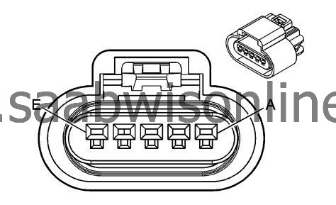
Connector Part Information
|
||||||||||||
Terminal Part Information
|
||||||||||||
B75B Mass Air Flow/Intake Air Temerature Sensor (LDK)
| Pin | Wire | Circuit | Operation |
|
A
|
0.5 GN/WH
|
492
|
Mass Air Flow Sensor Signal
|
|
B
|
0.5 BK
|
450
|
Ground
|
|
C
|
VT/YE
|
539
|
Run/Crank Ignition 1 Voltage
|
|
D
|
0.5 BK/VT
|
2760
|
Intake Air Temperature Sensor Low Reference
|
|
E
|
0.5 BN/VT
|
472
|
Intake Air Temperature Sensor Signal
|
| B78A Front Object Sensor - Left Outer |
Connector Part Information
|
||||||||||||
Terminal Part Information
|
||||||||||||
B78A Front Object Sensor - Left Outer
| Pin | Wire Color | Circuit No. | Operation |
|
1
|
0.5 YE/VT
|
5213
|
Front Parking Left/Right/Mid Sensor
|
|
2
|
0.5 BK/BU
|
5214
|
Low Reference
|
|
3
|
0.5 VT/WH
|
5215
|
Front Parking Left Corner Sensor
|
|
3
|
0.5 VT/WH
|
5215
|
Front Parking Left Corner Sensor
|
| B78B Front Object Sensor - Right Outer |
Connector Part Information
|
||||||||||||
Terminal Part Information
|
||||||||||||
B78B Front Object Sensor - Right Outer
| Pin | Wire Color | Circuit No. | Operation |
|
1
|
0.5 YE/VT
|
5213
|
Front Parking Left/Right/Mid Sensor
|
|
2
|
0.5 BK/BU
|
5214
|
Low Reference
|
|
3
|
0.5 WH/GY
|
5217
|
Front Parking Right Corner Sensor
|
|
3
|
0.5 WH/GY
|
5217
|
Front Parking Right Corner Sensor
|
| B78C Front Object Sensor - Left Middle |
Connector Part Information
|
||||||||||||
Terminal Part Information
|
||||||||||||
B78C Front Object Sensor - Left Middle
| Pin | Wire Color | Circuit No. | Operation |
|
1
|
0.5 YE/VT
|
5213
|
Front Parking Left/Right/Mid Sensor
|
|
2
|
0.5 BK/BU
|
5214
|
Low Reference
|
|
3
|
0.5 YE/GY
|
5216
|
Front Parking Left Mid Sensor
|
|
3
|
0.5 YE/GY
|
5216
|
Front Parking Left Mid Sensor
|
| B78D Front Object Sensor - Right Middle |
Connector Part Information
|
||||||||||||
Terminal Part Information
|
||||||||||||
B78D Front Object Sensor - Right Middle
| Pin | Wire Color | Circuit No. | Operation |
|
1
|
0.5 YE/VT
|
5213
|
Front Parking Left/Right/Mid Sensor
|
|
2
|
0.5 BK/BU
|
5214
|
Low Reference
|
|
3
|
0.5 VT/GY
|
5218
|
Front Parking Right Mid Sensor
|
|
3
|
0.5 VT/GY
|
5218
|
Front Parking Right Mid Sensor
|
| B78E Rear Object Sensor - Left Middle |
Connector Part Information
|
||||||||||||
Terminal Part Information
|
||||||||||||
B78E Rear Object Sensor - Left Middle
| Pin | Wire Color | Circuit No. | Operation |
|
1
|
0.5 BN/WH
|
2374
|
Object Sensor Supply Voltage
|
|
2
|
0.5 BK/GY
|
2379
|
Low Reference
|
|
3
|
0.5 YE/BU
|
2376
|
Left Rear Middle Object Sensor Signal
|
| B78F Rear Object Sensor - Right Middle |
Connector Part Information
|
||||||||||||
Terminal Part Information
|
||||||||||||
B78F Rear Object Sensor - Right Middle
| Pin | Wire Color | Circuit No. | Operation |
|
1
|
0.5 BN/WH
|
2374
|
Object Sensor Supply Voltage
|
|
2
|
0.5 BK/GY
|
2379
|
Low Reference
|
|
3
|
0.5 YE/WH
|
2377
|
Right Rear Middle Object Sensor Signal
|
| B78G Rear Object Sensor - Left Outer |
Connector Part Information
|
||||||||||||
Terminal Part Information
|
||||||||||||
B78G Rear Object Sensor - Left Outer
| Pin | Wire Color | Circuit No. | Operation |
|
1
|
0.5 BN/WH
|
2374
|
Object Sensor Supply Voltage
|
|
2
|
0.5 BK/GY
|
2379
|
Low Reference
|
|
3
|
0.5 YE
|
2375
|
Left Rear Corner Object Sensor Signal
|
| B78H Rear Object Sensor - Right Outer |
Connector Part Information
|
||||||||||||
Terminal Part Information
|
||||||||||||
B78H Rear Object Sensor - Right Outer
| Pin | Wire Color | Circuit No. | Operation |
|
1
|
0.5 BN/WH
|
2374
|
Object Sensor Supply Voltage
|
|
2
|
0.5 BK/GY
|
2379
|
Low Reference
|
|
3
|
0.5 YE/VT
|
2378
|
Right Rear Corner Object Sensor Signal
|
| B7B Air Temperature Sensor - Duct Lower |
Connector Part Information
|
||||||||||||
Terminal Part Information
|
||||||||||||
B7B Air Temperature Sensor - Duct Lower
| Pin | Wire Color | Circuit No. | Operation |
|
A
|
0.35 BN/BK
|
405
|
Lower Air Temperature Sensor Signal
|
|
B
|
0.35 BK/YE
|
407
|
Low Reference
|
| B7F Air Temperature Sensor - Duct Upper (CJ4) |
Connector Part Information
|
||||||||||||
Terminal Part Information
|
||||||||||||
B7F Air Temperature Sensor - Duct Upper (CJ4)
| Pin | Wire Color | Circuit No. | Operation |
|
A
|
0.35 BN
|
404
|
Upper Air Temperature Sensor Signal
|
|
B
|
0.35 BK/YE
|
407
|
Low Reference
|
| B80 Park Brake Switch |
Connector Part Information
|
||||||||||||
Terminal Part Information
|
||||||||||||
B80 Park Brake Switch
| Pin | Wire Color | Circuit No. | Operation |
|
1
|
0.5 YE
|
1492
|
Park Brake Switch Supply Voltage
|
|
2
|
0.5 BU/VT
|
1134
|
Park Brake Switch Signal
|
|
3
|
0.5 YE/RD
|
7683
|
Park Brake Release Switch Voltage Reference
|
|
4
|
0.5 BN
|
6107
|
Park Brake Apply Switch Signal
|
|
5
|
0.5 BU/BK
|
6108
|
Park Brake Release Switch Signal
|
|
6
|
0.5 YE
|
6817
|
LED Backlight Dimming Control
|
|
7
|
0.5 GY/RD
|
7684
|
Park Brake Apply Switch Voltage Reference
|
|
8
|
0.5 BK/WH
|
2451
|
Signal Ground
|
| B87 Rearview Camera |
Connector Part Information
|
||||||||||||
Terminal Part Information
|
||||||||||||
B87 Rearview Camera
| Pin | Wire Color | Circuit No. | Operation |
|
1
|
0.5 GY/YE
|
6972
|
Camera Signal #2 +
|
|
2
|
0.5 BARE
|
6974
|
Camera Drain Wire
|
|
3
|
0.5 BN/WH
|
24
|
Backup Lamp Supply Voltage
|
|
4
|
0.5 WH/BU
|
6973
|
Camera Signal #2
|
|
5
|
0.5 BK/WH
|
2351
|
Signal Ground
|
|
6
|
0.5 RD/GY
|
2840
|
Battery Positive Voltage
|
| B88LR Seat Belt Switch - Left Rear (UH5) |
Connector Part Information
|
||||||||||||
Terminal Part Information
|
||||||||||||
B88LR Seat Belt Switch - Left Rear (UH5)
| Pin | Wire Color | Circuit No. | Operation |
|
1
|
0.5 YE/OG
|
5161
|
Left Rear Seat Belt Switch Signal
|
|
1
|
0.5 YE/OG
|
5161
|
Left Rear Seat Belt Switch Signal
|
|
2
|
0.5 BK/OG
|
1361
|
Low Reference
|
| B88MR Seat Belt Switch - Rear Middle (UH5) |
Connector Part Information
|
||||||||||||
Terminal Part Information
|
||||||||||||
B88MR Seat Belt Switch - Rear Middle (UH5)
| Pin | Wire Color | Circuit No. | Operation |
|
1
|
0.5 BU/OG
|
5163
|
Center Rear Seat Belt Switch Signal
|
|
1
|
0.5 BU/OG
|
5163
|
Center Rear Seat Belt Switch Signal
|
|
2
|
0.5 BK/OG
|
1361
|
Low Reference
|
| B88RR Seat Belt Switch - Right Rear (UH5) |
Connector Part Information
|
||||||||||||
Terminal Part Information
|
||||||||||||
B88RR Seat Belt Switch - Right Rear (UH5)
| Pin | Wire Color | Circuit No. | Operation |
|
1
|
0.5 BN/OG
|
5162
|
Right Rear Seat Belt Switch Signal
|
|
1
|
0.5 BN/OG
|
5162
|
Right Rear Seat Belt Switch Signal
|
|
2
|
0.5 BK/OG
|
1361
|
Low Reference
|
| B9 Ambient Air Temperature Sensor |
Connector Part Information
|
||||||||||||
Terminal Part Information
|
||||||||||||
B9 Ambient Air Temperature Sensor
| Pin | Wire Color | Circuit No. | Operation |
|
1
|
0.5 BU/GY
|
636
|
Outside Ambient Air Temperature Sensor Signal
|
|
2
|
0.5 BK/BU
|
61
|
Outside Ambient Temperature Sensor Low Reference
|
| B94L Side Object Sensor - Left (UFT) |
Connector Part Information
|
||||||||||||
Terminal Part Information
|
||||||||||||
B94L Side Object Sensor - Left (UFT)
| Pin | Wire Color | Circuit No. | Operation |
|
1
|
-
|
-
|
Not used
|
|
2
|
0.5 GY
|
5861
|
Passenger Side Object Detection LED Signal (1)
|
|
2
|
0.5 GY/YE
|
5853
|
Driver Side Object Detection LED Signal (1)
|
|
3
|
-
|
-
|
Not used
|
|
4
|
0.5 BK/WH
|
2351
|
Signal Ground
|
|
5
|
0.5 GN
|
5060
|
Low Speed GMLAN Serial Data
|
|
6
|
0.5 GN
|
5060
|
Low Speed GMLAN Serial Data
|
|
7
|
0.5 RD/GN
|
1840
|
Battery Positive Voltage
|
|
8
|
-
|
-
|
Not used
|
| B94R Side Object Sensor - Right (UFT) |
Connector Part Information
|
||||||||||||
Terminal Part Information
|
||||||||||||
B94R Side Object Sensor - Right (UFT)
| Pin | Wire Color | Circuit No. | Operation |
|
1
|
-
|
-
|
Not used
|
|
2
|
0.5 GY
|
5861
|
Passenger Side Object Detection LED Signal (1)
|
|
2
|
0.5 GY/YE
|
5853
|
Driver Side Object Detection LED Signal (1)
|
|
3
|
0.5 BK/WH
|
2351
|
Signal Ground
|
|
4
|
0.5 BK/WH
|
2351
|
Signal Ground
|
|
5
|
0.5 GN
|
5060
|
Low Speed GMLAN Serial Data
|
|
6
|
-
|
-
|
Not used
|
|
7
|
0.5 RD/GN
|
1840
|
Battery Positive Voltage
|
|
8
|
-
|
-
|
Not used
|
| B99 Steering Wheel Angle Sensor |
Connector Part Information
|
|||||||||||||||
Terminal Part Information
|
|||||||||||||||
B99 Steering Wheel Angle Sensor
| Pin | Wire Color | Circuit No. | Operation |
|
1
|
0.5 WH
|
6106
|
High Speed GMLAN Serial Data (-) (2)
|
|
1
|
0.5 WH
|
6106
|
High Speed GMLAN Serial Data (-) (2)
|
|
2
|
-
|
-
|
Not used
|
|
3
|
0.5 BU/YE
|
6105
|
High Speed GMLAN Serial Data (+) (2)
|
|
4
|
-
|
-
|
Not used
|
|
5
|
0.35 GN/BN
|
2087
|
Combined Vehicle Inertial Sensor Supply Voltage
|
|
6
|
0.5 BK/WH
|
1551
|
Signal Ground
|
| C1 Battery ( - ) |
Connector Part Information
|
||||||||||||
Terminal Part Information
|
||||||||||||
C1 Battery ( - )
| Pin | Wire Color | Circuit No. | Operation |
|
A
|
35 BK
|
150
|
Ground
|
|
A
|
35 BK
|
150
|
Ground
|
| C3 Telematics Communication Interface Control Module Battery |
Connector Part Information
|
||||||||||||
Terminal Part Information
|
||||||||||||
C3 Telematics Communication Interface Control Module Battery
| Pin | Wire Color | Circuit No. | Operation |
|
A
|
0.5 YE/VT
|
5235
|
Battery Backup Supply Voltage
|
|
B
|
0.5 BK/VT
|
5167
|
Low Reference
|
| E13L Headlamp - Left |
Connector Part Information
|
|||||||||||||||
Terminal Part Information
|
|||||||||||||||
E13L Headlamp - Left
| Pin | Wire Color | Circuit No. | Operation |
|
1
|
1.5 BK
|
1750
|
Ground
|
|
2
|
1.5 WH
|
711
|
Left Headlamp High Beam Supply Voltage
|
|
3
|
1 YE
|
712
|
Left Headlamp Low Beam Supply Voltage
|
|
3
|
1.5 YE
|
712
|
Left Headlamp Low Beam Supply Voltage
|
|
4
|
0.5 VT/GY
|
709
|
Left Park Lamp Supply Voltage
|
|
5
|
-
|
-
|
Not used
|
|
6
|
0.75 VT/BK
|
339
|
Run/Crank Ignition 1 Voltage
|
|
6
|
1 BN/YE
|
189
|
Headlamp Leveling Motor Supply Voltage
|
|
7
|
1.5 BK
|
1750
|
Ground
|
|
7
|
0.5 GN/BN
|
7529
|
Linear Interconnect Network Bus 7
|
|
8
|
0.5 BN/YE
|
189
|
Headlamp Leveling Motor Supply Voltage
|
|
8
|
1 BK
|
1750
|
Ground
|
|
9
|
1 GY/BU
|
7538
|
Left Front DRL Supply Voltage
|
|
10
|
1.5 BK
|
1150
|
Ground
|
| E13R Headlamp - Right |
Connector Part Information
|
|||||||||||||||
Terminal Part Information
|
|||||||||||||||
E13R Headlamp - Right
| Pin | Wire Color | Circuit No. | Operation |
|
1
|
1.5 BK
|
1450
|
Ground
|
|
2
|
1.5 WH
|
311
|
Right Headlamp High Beam Supply Voltage
|
|
3
|
1 YE
|
312
|
Right Headlamp Low Beam Supply Voltage
|
|
3
|
1.5 YE
|
312
|
Right Headlamp Low Beam Supply Voltage
|
|
4
|
0.5 GY/BN
|
309
|
Right Park Lamp Supply Voltage
|
|
5
|
-
|
-
|
Not used
|
|
6
|
0.75 VT/BK
|
339
|
Run/Crank Ignition 1 Voltage
|
|
6
|
1 BN/YE
|
189
|
Headlamp Leveling Motor Supply Voltage
|
|
7
|
0.5 GN/WH
|
7530
|
Linear Interconnect Network Bus 8
|
|
7
|
2.5 BK
|
1450
|
Ground
|
|
8
|
0.5 BN/YE
|
189
|
Headlamp Leveling Motor Supply Voltage
|
|
8
|
1.5 BK
|
1450
|
Ground
|
|
9
|
1 BU/BN
|
7539
|
Right Front DRL Supply Voltage
|
|
10
|
1.5 BK
|
1050
|
Ground
|
| E18 Rear Defogger Grid X1 |
Connector Part Information
|
||||||||||||
Terminal Part Information
|
||||||||||||
E18 Rear Defogger Grid X1
| Pin | Wire Color | Circuit No. | Operation |
|
1
|
4 BN/VT
|
293
|
Rear Defog Element Supply Voltage
|
|
1
|
4 BN/VT
|
293
|
Rear Defog Element Supply Voltage
|
| E1C Accent Lamp - Driver Door Handle |
Connector Part Information
|
||||||||||||
Terminal Part Information
|
||||||||||||
E1C Accent Lamp - Driver Door Handle
| Pin | Wire Color | Circuit No. | Operation |
|
1
|
0.5 WH/YE
|
7557
|
LED Ambient Lighting Control 1
|
|
1
|
0.5 WH/YE
|
7557
|
LED Ambient Lighting Control 1
|
|
2
|
0.5 BK
|
2350
|
Ground
|
| E1D Accent Lamp - Driver Door (TSQ) |
Connector Part Information
|
||||||||||||
Terminal Part Information
|
||||||||||||
E1D Accent Lamp - Driver Door (TSQ)
| Pin | Wire Color | Circuit No. | Operation |
|
1
|
0.5 WH/YE
|
7557
|
LED Ambient Lighting Control 1
|
|
2
|
0.5 BK
|
1550
|
Ground
|
| E1E Accent Lamp - Left Rear Door Handle (TSQ) |
Connector Part Information
|
||||||||||||
Terminal Part Information
|
||||||||||||
E1E Accent Lamp - Left Rear Door Handle (TSQ)
| Pin | Wire Color | Circuit No. | Operation |
|
1
|
0.5 WH/YE
|
7557
|
LED Ambient Lighting Control 1
|
|
2
|
0.5 BK
|
2350
|
Ground
|
| E1F Accent Lamp - Right Rear Door Handle (TSQ) |
Connector Part Information
|
||||||||||||
Terminal Part Information
|
||||||||||||
E1F Accent Lamp - Right Rear Door Handle (TSQ)
| Pin | Wire Color | Circuit No. | Operation |
|
1
|
0.5 WH/YE
|
7557
|
LED Ambient Lighting Control 1
|
|
2
|
0.5 BK
|
2050
|
Ground
|
| E1J Accent Lamp - Left Lower Instrument Panel |
Connector Part Information
|
||||||||||||
Terminal Part Information
|
||||||||||||
E1J Accent Lamp - Left Lower Instrument Panel
| Pin | Wire Color | Circuit No. | Operation |
|
1
|
0.5 WH/YE
|
7557
|
LED Ambient Lighting Control 1
|
|
2
|
0.5 BK
|
1550
|
Ground
|
| E1LR Accent Lamp - Left Rear Door (TSQ) |
Connector Part Information
|
||||||||||||
Terminal Part Information
|
||||||||||||
E1LR Accent Lamp - Left Rear Door (TSQ)
| Pin | Wire Color | Circuit No. | Operation |
|
1
|
0.5 WH/YE
|
7557
|
LED Ambient Lighting Control 1
|
|
2
|
0.5 BK
|
2350
|
Ground
|
| E1M Accent Lamp - Passenger Door Handle. |
Connector Part Information
|
||||||||||||
Terminal Part Information
|
||||||||||||
E1M Accent Lamp - Passenger Door Handle.
| Pin | Wire Color | Circuit No. | Operation |
|
1
|
0.5 WH/YE
|
7557
|
LED Ambient Lighting Control 1
|
|
1
|
0.5 WH/YE
|
7557
|
LED Ambient Lighting Control 1
|
|
2
|
0.5 BK
|
2050
|
Ground
|
| E1P Accent Lamp - Passenger Door |
Connector Part Information
|
||||||||||||
Terminal Part Information
|
||||||||||||
E1P Accent Lamp - Passenger Door
| Pin | Wire Color | Circuit No. | Operation |
|
1
|
0.5 WH/YE
|
7557
|
LED Ambient Lighting Control 1
|
|
2
|
0.5 BK
|
1550
|
Ground
|
| E1RR Accent Lamp - Right Rear Door (TSQ) |
Connector Part Information
|
||||||||||||
Terminal Part Information
|
||||||||||||
E1RR Accent Lamp - Right Rear Door (TSQ)
| Pin | Wire Color | Circuit No. | Operation |
|
1
|
0.5 WH/YE
|
7557
|
LED Ambient Lighting Control 1
|
|
2
|
0.5 BK
|
2050
|
Ground
|
| E28 Center Console Compartment Lamp |
Connector Part Information
|
||||||||||||
Terminal Part Information
|
||||||||||||
E28 Center Console Compartment Lamp
| Pin | Wire Color | Circuit No. | Operation |
|
1
|
0.35 WH/YE
|
7557
|
LED Ambient Lighting Control 1
|
|
2
|
0.35 BK
|
1850
|
Ground
|
| E29LF Fog Lamp - Left Front |
Connector Part Information
|
||||||||||||
Terminal Part Information
|
||||||||||||
E29LF Fog Lamp - Left Front
| Pin | Wire Color | Circuit No. | Operation |
|
1
|
1.5 BK
|
1350
|
Ground
|
|
2
|
1.5 BN/VT
|
2234
|
Front Fog Lamp Supply Voltage
|
| E29R Fog Lamp - Rear (T79) |
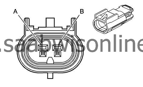
Connector Part Information
|
||||||||||||
Terminal Part Information
|
||||||||||||
E29R Fog Lamp - Rear (T79)
| Pin | Wire Color | Circuit No. | Operation |
|
A
|
0.5 BK
|
3350
|
Ground
|
|
B
|
0.5 BN/BU
|
1977
|
Rear Fog Lamp Relay Control
|
| E29RF Fog Lamp - Right Front |
Connector Part Information
|
||||||||||||
Terminal Part Information
|
||||||||||||
E29RF Fog Lamp - Right Front
| Pin | Wire Color | Circuit No. | Operation |
|
1
|
1.5 BK
|
1350
|
Ground
|
|
2
|
1.5 BN/VT
|
2234
|
Front Fog Lamp Supply Voltage
|
| E31L Sunshade Mirror Lamp - Left |
Connector Part Information
|
||||||||||||
Terminal Part Information
|
||||||||||||
E31L Sunshade Mirror Lamp - Left
| Pin | Wire Color | Circuit No. | Operation |
|
A
|
0.5 WH/BN
|
6815
|
Inadvertent Power Control
|
|
B
|
0.5 BK
|
1550
|
Ground
|
| E32 Cigarette Lighter Receptacle |
Connector Part Information
|
||||||||||||||||||||||||
Terminal Part Information
|
||||||||||||||||||||||||
E32 Cigarette Lighter Receptacle
| Pin | Wire Color | Circuit No. | Operation |
|
A
|
2.5 VT
|
2801
|
Retained Accessory Power Fuse Supply Voltage
|
|
B
|
0.5 YE
|
6817
|
LED Backlight Dimming Control
|
|
C
|
2.5 BK
|
1950
|
Ground
|
| E37M Dome/Reading Lamps - Middle |
Connector Part Information
|
||||||||||||
Terminal Part Information
|
||||||||||||
E37M Dome/Reading Lamps - Middle
| Pin | Wire Color | Circuit No. | Operation |
|
1
|
0.5 WH/BN
|
6815
|
Inadvertent Power Control
|
|
2
|
0.5 GY
|
157
|
Interior Lamp Control
|
|
3-5
|
-
|
-
|
Not used
|
|
6
|
0.5 BK
|
1550
|
Ground
|
| E38R Sunshade Mirror Lamp - Right |
Connector Part Information
|
||||||||||||
Terminal Part Information
|
||||||||||||
E38R Sunshade Mirror Lamp - Right
| Pin | Wire Color | Circuit No. | Operation |
|
A
|
0.5 WH/BN
|
6815
|
Inadvertent Power Control
|
|
B
|
0.5 BK
|
1550
|
Ground
|
| E40 Electrical Auxiliary Heater X1 |
Connector Part Information
|
||||||||||||
Terminal Part Information
|
||||||||||||
E40 Electrical Auxiliary Heater X1
| Pin | Wire Color | Circuit No. | Operation |
|
1
|
0.5 VT
|
3195
|
Auxiliary Heater Control
|
|
2
|
0.5 VT/GN
|
3039
|
Run/Crank Ignition 1 Voltage
|
|
2
|
0.5 VT/GN
|
3039
|
Run/Crank Ignition 1 Voltage
|
|
4
|
0.5 YE/GN
|
3196
|
Auxiliary Heater Status Signal
|
| E40 Electrical Auxiliary Heater X2 |

Connector Part Information
|
||||||||||||
Terminal Part Information
|
||||||||||||
E40 Electrical Auxiliary Heater X2
| Pin | Wire Color | Circuit No. | Operation |
|
1
|
10 RD/BU
|
4540
|
Battery Positive Voltage
|
|
2
|
10 BK
|
1350
|
Ground
|
| E45 Crankshaft Ventilation Heater (LBS) |
Connector Part Information
|
||||||||||||
Terminal Part Information
|
||||||||||||
E45 Crankshaft Ventilation Heater (LBS)
| Pin | Wire Color | Circuit No. | Operation |
|
1
|
0.5 YE/BU
|
6398
|
Positive Crankcase Valve Control
|
|
1
|
0.5 RD/BU
|
5293
|
Powertrain Main Relay Fused Supply (4)
|
| E4LF Turn Signal Lamp - Left Front |
Connector Part Information
|
||||||||||||
Terminal Part Information
|
||||||||||||
E4LF Turn Signal Lamp - Left Front
| Pin | Wire Color | Circuit No. | Operation |
|
1
|
0.75 BK
|
1350
|
Ground
|
|
2
|
0.75 BU/WH
|
1314
|
Left Front Turn Signal Lamp Supply Voltage
|
|
2
|
0.75 BU/WH
|
1314
|
Left Front Turn Signal Lamp Supply Voltage
|
| E4RF Turn Signal Lamp - Right Front |
Connector Part Information
|
||||||||||||
Terminal Part Information
|
||||||||||||
E4RF Turn Signal Lamp - Right Front
| Pin | Wire Color | Circuit No. | Operation |
|
1
|
0.75 BK
|
1350
|
Ground
|
|
2
|
0.75 GN/VT
|
1315
|
Right Front Turn Signal Lamp Supply Voltage
|
|
2
|
0.75 GN/VT
|
1315
|
Right Front Turn Signal Lamp Supply Voltage
|
| E5E Tail Lamp - Left |
Connector Part Information
|
|||||||||||||||||||||||||||||||||||||||
Terminal Part Information
|
|||||||||||||||||||||||||||||||||||||||
E5E Tail Lamp - Left
| Pin | Wire Color | Circuit No. | Operation |
|
A
|
0.5 VT/GY
|
709
|
Left Park Lamp Supply Voltage
|
|
B
|
0.75 BU/WH
|
1334
|
Left Rear Turn Signal Lamp Supply Voltage
|
|
C
|
0.5 GY/YE
|
7542
|
Left Rear Stop Lamp Supply Voltage
|
|
C
|
0.75 BU/WH
|
1334
|
Left Rear Turn Signal Lamp Supply Voltage
|
|
D
|
0.5 GN/WH
|
24
|
Backup Lamp Supply Voltage
|
|
D
|
0.75 GN/WH
|
24
|
Backup Lamp Supply Voltage
|
|
E
|
-
|
-
|
Not used
|
|
F
|
1.5 BK
|
3450
|
Ground
|
| E5F Tail Lamp - Right |
Connector Part Information
|
|||||||||||||||||||||||||||||||||||||||
Terminal Part Information
|
|||||||||||||||||||||||||||||||||||||||
E5F Tail Lamp - Right
| Pin | Wire Color | Circuit No. | Operation |
|
A
|
0.5 GY/BN
|
309
|
Right Park Lamp Supply Voltage
|
|
B
|
0.75 BU/VT
|
1335
|
Right Rear Turn Signal Lamp Supply Voltage
|
|
C
|
0.5 WH/YE
|
7541
|
Right Rear Stop Lamp Supply Voltage
|
|
C
|
0.75 BU/VT
|
1335
|
Right Rear Turn Signal Lamp Supply Voltage
|
|
D
|
0.5 GN/WH
|
24
|
Backup Lamp Supply Voltage
|
|
D
|
0.75 GN/WH
|
24
|
Backup Lamp Supply Voltage
|
|
E
|
-
|
-
|
Not used
|
|
F
|
1.5 BK
|
3250
|
Ground
|
| E6 Center High Mounted Stop Lamp |
Connector Part Information
|
|||||||||||||||
Terminal Part Information
|
|||||||||||||||
E6 Center High Mounted Stop Lamp
| Pin | Wire Color | Circuit No. | Operation |
|
2
|
0.75 BK
|
3250
|
Ground
|
|
3
|
0.5 VT/WH
|
5065
|
Stop Lamp Relay Coil Supply Voltage
|
| E8D Door Courtesy Lamp - Driver |
Connector Part Information
|
||||||||||||
Terminal Part Information
|
||||||||||||
E8D Door Courtesy Lamp - Driver
| Pin | Wire Color | Circuit No. | Operation |
|
1
|
0.5 GY
|
157
|
Interior Lamp Control
|
|
2
|
0.5 BK
|
1550
|
Ground
|
| E8E Rear Compartment Courtesy Lamp - Left |
Connector Part Information
|
||||||||||||
Terminal Part Information
|
||||||||||||
E8E Rear Compartment Courtesy Lamp - Left
| Pin | Wire Color | Circuit No. | Operation |
|
1
|
0.5 GN/GY
|
737
|
Trunk Lamp Control
|
|
2
|
0.5 BK
|
3350
|
Ground
|
| E8F Rear Compartment Courtesy Lamp - Right |
Connector Part Information
|
||||||||||||||||||||||||
Terminal Part Information
|
||||||||||||||||||||||||
E8F Rear Compartment Courtesy Lamp - Right
| Pin | Wire Color | Circuit No. | Operation |
|
1
|
0.5 GN/GY
|
737
|
Trunk Lamp Control
|
|
2
|
0.75 BK
|
3250
|
Ground
|
| E8J Instrument Panel Courtesy Lamp - Left |
Connector Part Information
|
||||||||||||
Terminal Part Information
|
||||||||||||
E8J Instrument Panel Courtesy Lamp - Left
| Pin | Wire Color | Circuit No. | Operation |
|
1
|
0.75 GY
|
157
|
Interior Lamp Control
|
|
2
|
0.75 BK
|
1650
|
Ground
|
| E8P Door Courtesy Lamp - Passenger |
Connector Part Information
|
||||||||||||
Terminal Part Information
|
||||||||||||
E8P Door Courtesy Lamp - Passenger
| Pin | Wire Color | Circuit No. | Operation |
|
1
|
0.5 GY
|
157
|
Interior Lamp Control
|
|
2
|
0.5 BK
|
2050
|
Ground
|
| F105 Passenger Instrument Panel Air Bag |
Connector Part Information
|
||||||||||||
Terminal Part Information
|
||||||||||||
F105 Passenger Instrument Panel Air Bag
| Pin | Wire Color | Circuit No. | Operation |
|
1
|
0.5 YE/OG
|
3025
|
Passenger IP Module Stage 1 High Control
|
|
2
|
0.5 OG/WH
|
3024
|
Passenger IP Module Stage 1 Low Control
|
|
3
|
0.5 BK
|
2450
|
Ground
|
|
4
|
0.5 GY/OG
|
3027
|
Passenger IP Module Stage 2 High Control
|
|
5
|
0.5 OG/VT
|
3026
|
Passenger IP Module Stage 2 Low Control
|
| F106LR Side Air Bag - Left Rear (AW7) |
Connector Part Information
|
||||||||||||
Terminal Part Information
|
||||||||||||
F106LR Side Air Bag - Left Rear (AW7)
| Pin | Wire Color | Circuit No. | Operation |
|
1
|
0.5 OG/GY
|
5223
|
Left Rear Side Impact SIR Inflator Supply Voltage
|
|
2
|
0.5 BN/OG
|
5224
|
Left Rear Side Impact SIR Inflator Control
|
|
3
|
0.5 BK
|
2450
|
Ground
|
| F106RR Side Air Bag - Right Rear (AW7) |
Connector Part Information
|
||||||||||||
Terminal Part Information
|
||||||||||||
F106RR Side Air Bag - Right Rear (AW7)
| Pin | Wire Color | Circuit No. | Operation |
|
1
|
0.5 VT/OG
|
5225
|
Right Rear Side Impact SIR Inflator Supply Voltage
|
|
2
|
0.5 OG/GY
|
5226
|
Right Rear Side Impact SIR Inflator Control
|
|
3
|
0.5 BK
|
2450
|
Ground
|
| G1 A/C Compressor |
Connector Part Information
|
||||||||||||
Terminal Part Information
|
||||||||||||
G1 A/C Compressor
| Pin | Wire | Circuit | Operation |
|
A
|
0.5 YE/BU
|
7574
|
Electric Variable Displacement Control (LAU/LDK)
|
|
0.5 YE/BU
|
729
|
A/C Compressor Clutch Solenoid Control (LBS)
|
|
|
B
|
0.5 BN/GN
|
7573
|
Electric Variable Displacement Supply (LAU/LDK)
|
|
0.5 BN/GN
|
59
|
A/C Compressor Clutch Supply Voltage (LBS)
|
| G10L Cooling Fan Motor-Left |
Connector Part Information
|
||||||||||||
Terminal Part Information
|
||||||||||||
G10L Cooling Fan Motor-Left
| Pin | Wire Color | Circuit No. | Operation |
|
1
|
6 RD/WH
|
532
|
Cooling Fan Motor Supply Voltage (2)
|
|
1
|
6 RD/YE
|
409
|
Cooling Fan Motor Supply Voltage (1)
|
|
2
|
6 GN
|
7625
|
Cooling Fan Motor Supply Voltage (4)
|
|
2
|
6 BU/VT
|
2364
|
Cooling Fan Speed Signal
|
|
3
|
6 BK/GN
|
504
|
Cooling Fan Motor Return
|
|
3
|
6 BK
|
1250
|
Ground
|
| G10R Cooling Fan Motor - Right |
Connector Part Information
|
||||||||||||
Terminal Part Information
|
||||||||||||
G10R Cooling Fan Motor - Right
| Pin | Wire Color | Circuit No. | Operation |
|
1
|
6 RD/YE
|
409
|
Cooling Fan Motor Supply Voltage (1)
|
|
1
|
6 RD/WH
|
532
|
Cooling Fan Motor Supply Voltage (2)
|
|
2
|
6 BU/VT
|
2364
|
Cooling Fan Speed Signal
|
|
2
|
6 GN
|
7625
|
Cooling Fan Motor Supply Voltage (4)
|
|
3
|
6 BK
|
1250
|
Ground
|
|
3
|
6 BK/GN
|
504
|
Cooling Fan Motor Return
|
| G13 Generator X2 (LAU) |
Connector Part Information
|
||||||||||||
Terminal Part Information
|
||||||||||||
G13 Generator X2 (LAU)
| Pin | Wire | Circuit | Operation |
|
1
|
0.5 BU/WH
|
225
|
Generator Turn On Signal
|
|
2
|
0.5 GY
|
23
|
Generator Field Duty Cycle Signal
|
| G13 Generator X2 (LBS or LDK) |
Connector Part Information
|
||||||||||||
Terminal Part Information
|
||||||||||||
G13 Generator X2 (LBS or LDK)
| Pin | Wire | Circuit | Operation |
|
1
|
0.5 BU/WH
|
225
|
Generator Turn On Signal
|
|
2
|
0.5 GY
|
23
|
Generator Field Duty Cycle Signal
|
| G16 Headlamp Washer Fluid Pump (CE4) |
Connector Part Information
|
||||||||||||
Terminal Part Information
|
||||||||||||
G16 Headlamp Washer Fluid Pump (CE4)
| Pin | Wire Color | Circuit No. | Operation |
|
1
|
2.5 BK
|
1550
|
Ground
|
|
2
|
2.5 VT
|
1197
|
Headlamp Washer Pump Control
|
| G18 High Pressure Fuel Pump (LBS) |
Connector Part Information
|
||||||||||||
Terminal Part Information
|
||||||||||||
G18 High Pressure Fuel Pump (LBS)
| Pin | Wire | Circuit | Operation |
|
1
|
0.5 YE/RD
|
7301
|
High Pressure Fuel Pump Actuator High Control
|
|
2
|
0.5 VT/BK
|
7300
|
High Pressure Fuel Pump Actuator Low Control
|
| G18 High Pressure Fuel Pump (LDK) |
Connector Part Information
|
||||||||||||
Terminal Part Information
|
||||||||||||
G18 High Pressure Fuel Pump (LDK)
| Pin | Wire | Circuit | Operation |
|
1
|
0.5 VT
|
7300
|
High Pressure Fuel Pump Actuator Low Control
|
|
2
|
0.5 YE/RD
|
7301
|
High Pressure Fuel Pump Actuator High Control
|
| G21 Secondary Air Injection Pump (LAU) |
Connector Part Information
|
||||||||||||
Terminal Part Information
|
||||||||||||
G21 Secondary Air Injection Pump (LAU)
| Pin | Wire | Circuit | Operation |
|
1
|
4 BK
|
150
|
Ground
|
|
2
|
4 BN/YE
|
78
|
Air Injection Reaction Pump Supply Voltage
|
| G24 Windshield Washer Pump |
Connector Part Information
|
||||||||||||
Terminal Part Information
|
||||||||||||
G24 Windshield Washer Pump
| Pin | Wire Color | Circuit No. | Operation |
|
1
|
1 GY/VT
|
228
|
Windshield Washer Pump Control
|
|
1
|
1 GY/VT
|
228
|
Windshield Washer Pump Control
|
|
2
|
1.5 BK
|
1550
|
Ground
|
|
2
|
1.5 BK
|
1150
|
Ground
|
| K17 Electronic Brake Control Module |
Connector Part Information
|
||||||||||||||||||||||||
Terminal Part Information
|
||||||||||||||||||||||||
K17 Electronic Brake Control Module
| Pin | Wire Color | Circuit No. | Operation |
|
1
|
6 RD/VT
|
1640
|
Battery Positive Voltage
|
|
2
|
-
|
-
|
Not used
|
|
3
|
0.5 YE
|
872
|
Wheel Speed Sensor Signal Right Front
|
|
3
|
0.5 YE
|
872
|
Wheel Speed Sensor Signal Right Front
|
|
4
|
0.5 GY/BN
|
7065
|
Wheel Speed Sensor Supply Voltage Right Front
|
|
4
|
0.5 GY/BN
|
7065
|
Wheel Speed Sensor Supply Voltage Right Front
|
|
5-9
|
-
|
-
|
Not used
|
|
10
|
0.5 GY/YE
|
7128
|
Wheel Speed Sensor Supply Voltage Right Rear
|
|
11
|
0.5 VT
|
882
|
Wheel Speed Sensor Signal Right Rear
|
|
12
|
-
|
-
|
Not used
|
|
13
|
6 BK
|
1450
|
Ground
|
|
14
|
0.5 GN/BN
|
2087
|
Combined Vehicle Inertial Sensor Supply Voltage
|
|
15
|
0.5 YE/RD
|
6031
|
5 Volt Reference
|
|
15
|
0.5 YE/RD
|
6031
|
5 Volt Reference
|
|
16
|
0.5 BK/YE
|
6032
|
Low Reference
|
|
16
|
0.5 BK/YE
|
6032
|
Low Reference
|
|
17
|
0.5 BU
|
2500
|
High Speed GMLAN Serial Data (+) (1)
|
|
18
|
0.5 WH
|
2501
|
High Speed GMLAN Serial Data (-) (1)
|
|
19
|
-
|
-
|
Not used
|
|
20
|
0.5 WH
|
6106
|
High Speed GMLAN Serial Data (-) (2)
|
|
20
|
0.5 WH
|
6106
|
High Speed GMLAN Serial Data (-) (2)
|
|
21
|
0.5 BU/YE
|
6105
|
High Speed GMLAN Serial Data (+) (2)
|
|
21
|
0.5 BU/YE
|
6105
|
High Speed GMLAN Serial Data (+) (2)
|
|
22
|
0.5 YE/VT
|
6030
|
Brake Vacuum Sensor Signal
|
|
22
|
0.5 YE/VT
|
6030
|
Brake Vacuum Sensor Signal
|
|
23-24
|
-
|
-
|
Not used
|
|
25
|
2.5 RD/BU
|
1542
|
Battery Positive Voltage
|
|
26
|
-
|
-
|
Not used
|
|
27
|
0.5 GY
|
830
|
Wheel Speed Sensor Signal Left Front
|
|
27
|
0.5 GY
|
830
|
Wheel Speed Sensor Signal Left Front
|
|
28
|
0.5 GY/WH
|
7064
|
Wheel Speed Sensor Supply Voltage Left Front
|
|
28
|
0.5 GY/WH
|
7064
|
Wheel Speed Sensor Supply Voltage Left Front
|
|
29
|
0.5 GN/GY
|
333
|
Brake Fluid Level Sensor Signal
|
|
29
|
0.5 GN/GY
|
333
|
Brake Fluid Level Sensor Signal
|
|
30-32
|
-
|
-
|
Not used
|
|
33
|
0.5 WH/BU
|
5986
|
Serial Data Communication Enable
|
|
34
|
0.5 GY
|
1903
|
AAS Wheel Speed Sensor Signal Left Front
|
|
35
|
0.5 GY/BK
|
7127
|
Wheel Speed Sensor Supply Voltage Left Rear
|
|
36
|
0.5 BU
|
884
|
Wheel Speed Sensor Signal Left Rear
|
|
37
|
-
|
-
|
Not used
|
|
38
|
2.5 BK
|
1450
|
Ground
|
| K19 Suspension Control Module (F45) |
Connector Part Information
|
||||||||||||
Terminal Part Information
|
||||||||||||
K19 Suspension Control Module (F45)
| Pin | Wire Color | Circuit No. | Operation |
|
1
|
0.75 RD/WH
|
1040
|
Battery Positive Voltage
|
|
2
|
0.75 GN/GY
|
1119
|
Right Rear Damping Servo Control
|
|
3
|
0.75 BN/GN
|
1118
|
Right Rear Damping Servo Supply Voltage
|
|
4
|
0.75 BU/GY
|
1114
|
Left Rear Damping Servo Supply Voltage
|
|
5
|
0.75 GN/VT
|
1115
|
Left Rear Damping Servo Control
|
|
6
|
0.5 WH/BU
|
5986
|
Serial Data Communication Enable
|
|
7
|
0.5 WH/YE
|
3256
|
Rear Accelerometer Signal
|
|
8
|
0.5 WH/VT
|
3259
|
Left Front Accelerometer Signal
|
|
8
|
0.5 WH/VT
|
3259
|
Left Front Accelerometer Signal
|
|
9
|
0.5 WH/BN
|
3253
|
Right Front Accelerometer Signal
|
|
9
|
0.5 WH/BN
|
3253
|
Right Front Accelerometer Signal
|
|
10
|
0.5 WH
|
1100
|
Left Front Wheel Damping Accelerometer Signal
|
|
10
|
0.5 WH
|
1100
|
Left Front Wheel Damping Accelerometer Signal
|
|
11
|
0.5 WH
|
1106
|
Right Front Wheel Damping Accelerometer Signal
|
|
11
|
0.5 WH
|
1106
|
Right Front Wheel Damping Accelerometer Signal
|
|
12
|
0.75 YE/RD
|
1817
|
Left Front Wheel Accelerometer Voltage Reference
|
|
13
|
0.75 GY/BU
|
1113
|
Left Front Damping Servo Control
|
|
13
|
0.75 GY/BU
|
1113
|
Left Front Damping Servo Control
|
|
14
|
0.75 BN/WH
|
1107
|
Left Front Damping Servo Supply Voltage
|
|
14
|
0.75 BN/WH
|
1107
|
Left Front Damping Servo Supply Voltage
|
|
15
|
0.75 BN/BU
|
1116
|
Right Front Damping Servo Supply Voltage
|
|
15
|
0.75 BN/BU
|
1116
|
Right Front Damping Servo Supply Voltage
|
|
16
|
0.75 GY/WH
|
1117
|
Right Front Damping Servo Control
|
|
16
|
0.75 GY/WH
|
1117
|
Right Front Damping Servo Control
|
|
17
|
0.75 RD/WH
|
1040
|
Battery Positive Voltage
|
|
18
|
0.75 BK/WH
|
2151
|
Signal Ground
|
|
19
|
0.75 BK/WH
|
2151
|
Signal Ground
|
|
20
|
0.75 BK/BN
|
1099
|
Low Reference
|
|
21
|
0.5 BU
|
2500
|
High Speed GMLAN Serial Data (+) (1)
|
|
22
|
0.5 BU
|
2500
|
High Speed GMLAN Serial Data (+) (1)
|
|
23
|
0.5 BU
|
2500
|
High Speed GMLAN Serial Data (+) (1)
|
|
24
|
0.5 WH
|
2501
|
High Speed GMLAN Serial Data (-) (1)
|
|
25
|
0.5 WH
|
2501
|
High Speed GMLAN Serial Data (-) (1)
|
|
26
|
0.5 WH
|
2501
|
High Speed GMLAN Serial Data (-) (1)
|
|
27-28
|
0.5 BU/YE
|
6105
|
High Speed GMLAN Serial Data (+) (2)
|
|
29
|
0.5 BU/YE
|
6105
|
High Speed GMLAN Serial Data (+) (2)
|
|
30
|
0.5 WH
|
6106
|
High Speed GMLAN Serial Data (-) (2)
|
|
31-32
|
0.5 BU/YE
|
6105
|
High Speed GMLAN Serial Data (+) (2)
|
| K20 Engine Control Module X1 (LAU) |
Connector Part Information
|
||||||||||||
Terminal Part Information
|
||||||||||||
K20 Engine Control Module X1 (LAU)
| Pin | Wire | Circuit | Operation |
|
1
|
0.5 GY/BU
|
5282
|
Camshaft Phaser Exhaust Solenoid (1)
|
|
2
|
0.5 VT/BN
|
5284
|
Camshaft Phaser Intake Solenoid (1)
|
|
3
|
-
|
-
|
Not used
|
|
4
|
0.8 BN/BU
|
846
|
Fuel Injector Control (6)
|
|
5
|
0.5 GN/BU
|
428
|
EVAP Canister Purge Solenoid Control
|
|
6
|
-
|
-
|
Not used
|
|
7
|
0.5 YE/VT
|
5275
|
Camshaft Position Intake Sensor (1)
|
|
8
|
-
|
-
|
Not used
|
|
9
|
0.5 YE/RD
|
5274
|
Camshaft Position Exhaust Sensor (2)
|
|
10
|
0.5 GY
|
23
|
Generator Field Duty Cycle Signal
|
|
11
|
0.5 BN/GN
|
1174
|
Oil Level Switch Signal
|
|
12
|
-
|
-
|
Not used
|
|
13
|
0.5 BK/BU
|
2129
|
Ignition Control Low Reference Bank 1
|
|
14
|
-
|
-
|
Not used
|
|
15
|
0.5 GY
|
7376
|
Camshaft Position Sensor 5V Supply Voltage
|
|
16
|
0.5 BN/YE
|
5268
|
Overrun Air Valve Solenoid
|
|
17
|
-
|
-
|
Not used
|
|
18
|
0.5 BN/YE
|
258
|
Waste Gate Solenoid Control
|
|
19-23
|
-
|
-
|
Not used
|
|
24
|
0.5 WH
|
560
|
Throttle Relaxer Motor Supply Voltage
|
|
25
|
0.5 GN/BN
|
5283
|
Camshaft Phaser Exhaust Solenoid (2)
|
|
26
|
0.8 BN/VT
|
1746
|
Fuel Injector Control (3)
|
|
27
|
-
|
-
|
Not used
|
|
28
|
0.8 BN/GN
|
845
|
Fuel Injector Control (5)
|
|
29
|
-
|
-
|
Not used
|
|
30
|
0.5 BU/WH
|
225
|
Generator Turn On Signal
|
|
31-32
|
-
|
-
|
Not used
|
|
33
|
0.5 YE
|
5276
|
Camshaft Position Intake Sensor (2)
|
|
34
|
0.5 VT/BK
|
5273
|
Camshaft Position Exhaust Sensor (1)
|
|
35
|
0.5 GN
|
573
|
Crankshaft Position Sensor Signal (1)
|
|
36-38
|
-
|
-
|
Not used
|
|
39
|
0.5 BN/RD
|
416
|
Throttle Position Sensor 5 Volt Reference
|
|
40
|
0.5 BN/RD
|
474
|
5 Volt Reference
|
|
41
|
0.5 BK/VT
|
632
|
Camshaft Position Sensor Low Reference
|
|
42
|
-
|
-
|
Not used
|
|
43
|
0.5 BK/WH
|
51
|
Ground
|
|
44
|
0.5 BK/WH
|
151
|
Signal Ground
|
|
45
|
0.5 VT/BU
|
2867
|
Crankshaft Position Sensor Supply Voltage
|
|
46
|
0.5BK/VT
|
574
|
Crankshaft Position Sensor Low Reference (1)
|
|
47
|
-
|
-
|
Not used
|
|
48
|
0.5 BK/GY
|
561
|
Throttle Relaxer Motor Low Reference
|
|
49
|
0.5 GN
|
5272
|
Camshaft Phaser Intake Solenoid (2)
|
|
50
|
0.8 BN/YE
|
844
|
Fuel Injector Control (4)
|
|
51
|
0.8 BN/VT
|
1744
|
Fuel Injector Control (1)
|
|
52
|
0.8 YE/WH
|
1745
|
Fuel Injector Control (2)
|
|
53-54
|
-
|
-
|
Not used
|
|
55
|
0.5 BU/VT
|
2121
|
Ignition Control (1)
|
|
56
|
0.5 GN/BU
|
2123
|
Ignition Control (3)
|
|
57
|
0.5 BU/GY
|
2125
|
Ignition Control (5)
|
|
58
|
-
|
-
|
Not used
|
|
59
|
0.5 VT/GY
|
496
|
Knock Sensor Signal (1)
|
|
60
|
0.5 BK/YE
|
2303
|
Knock Sensor Low Reference (2)
|
|
61
|
0.5 YE/BN
|
331
|
Oil Pressure Sensor Signal
|
|
62-63
|
-
|
-
|
Not used
|
|
64
|
0.5 BK/GN
|
469
|
Manifold Absolute Pressure Sensor Low Reference
|
|
65
|
-
|
-
|
Not used
|
|
66
|
0.5 GN/WH
|
432
|
Manifold Absolute Pressure Sensor Signal
|
|
67
|
0.5 BK/GN
|
1664
|
Heated Oxygen Sensor Low Signal Bank 1 Sensor (1)
|
|
68-77
|
-
|
-
|
Not used
|
|
78
|
0.5 BK/BU
|
2129
|
Ignition Control Low Reference Bank 1
|
|
79
|
0.5 BU/WH
|
2122
|
Ignition Control (2)
|
|
80
|
0.5 YE/BU
|
2124
|
Ignition Control (4)
|
|
81
|
0.5 BN/BU
|
2126
|
Ignition Control (6)
|
|
82
|
0.5 BU
|
410
|
Coolant Temperature Sensor Signal
|
|
83
|
0.5 BK/YE
|
1716
|
Knock Sensor Low Reference (1)
|
|
84
|
0.5 WH/GY
|
1876
|
Knock Sensor Signal (2)
|
|
85
|
-
|
-
|
Not used
|
|
86
|
0.5 GY/BU
|
6118
|
Manifold Air Temperature Sensor Signal
|
|
87
|
0.5 WH/BN
|
6331
|
Air Injection Reaction Pump Pressure Sensor Signal
|
|
88
|
0.5 BK/YE
|
2752
|
Low Reference
|
|
89
|
0.5 BN/BU
|
486
|
Throttle Position Sensor Signal (2)
|
|
90
|
0.5 BN/GN
|
485
|
Throttle Position Sensor Signal (1)
|
|
91
|
-
|
-
|
Not used
|
|
92
|
0.5 GN
|
1665
|
Heated Oxygen Sensor High Signal Bank 1 Sensor (1)
|
|
93-94
|
-
|
-
|
Not used
|
|
95
|
0.5 BN/RD
|
2704
|
Manifold Absolute Pressure Sensor 5 Volt Reference
|
|
96
|
0.5 GY/WH
|
3113
|
Heated Oxygen Sensor Heater Low Control Bank 1 Sensor (1)
|
| K20 Engine Control Module X1 (LBS) |
Connector Part Information
|
||||||||||||
Terminal Part Information
|
||||||||||||
K20 Engine Control Module X1 (LBS)
| Pin | Wire | Circuit | Operation |
|
1
|
2.5 RD/BU
|
5290
|
Powertrain Main Relay Fused Supply (1)
|
|
2
|
2.5 BK
|
450
|
Ground
|
|
3
|
2.5 RD/BU
|
5290
|
Powertrain Main Relay Fused Supply (1)
|
|
4
|
2.5 BK
|
450
|
Ground
|
|
5
|
2.5 RD/BU
|
5290
|
Powertrain Main Relay Fused Supply (1)
|
|
6
|
2.5 BK
|
450
|
Ground
|
|
7
|
0.5 GY/WH
|
3113
|
Heated Oxygen Sensor Heater Low Control Bank 1 Sensor (1)
|
|
8-13
|
-
|
-
|
Not used
|
|
14
|
0.5 YE/BU
|
1578
|
Fuel Temperature Signal
|
|
15
|
0.5 YE
|
6111
|
Clutch Apply Sensor Signal (MR6)
|
|
16
|
-
|
-
|
Not used
|
|
17
|
0.5 BK/BN
|
5514
|
A/C Refrigerant Pressure Sensor Low Reference
|
|
18-20
|
-
|
-
|
Not used
|
|
21
|
0.5 BU/WH
|
225
|
Generator Turn On Signal
|
|
22
|
0.5 BN/RD
|
1274
|
Accelerator Pedal Position 5 Volt Reference (2)
|
|
23
|
-
|
-
|
Not used
|
|
24
|
0.5 GY/RD
|
6109
|
Clutch Apply Sensor Voltage Reference (MR6)
|
|
25
|
-
|
-
|
Not used
|
|
26
|
0.8 BN/RD
|
2700
|
A/C Pressure Sensor 5 Volt Reference
|
|
27
|
0.5 GY
|
6054
|
Exhaust Pressure Sensor 5 Volt Reference (1)
|
|
28
|
0.5 BN/RD
|
1164
|
Accelerator Pedal Position 5 Volt Reference (1)
|
|
29-31
|
-
|
-
|
Not used
|
|
32
|
0.5 GN
|
380
|
A/C Refrigerant Pressure Sensor Signal
|
|
33-36
|
-
|
-
|
Not used
|
|
37
|
0.5 BU/VT
|
1589
|
Primary Fuel Level Sensor Signal
|
|
38
|
0.5 WH/BU
|
6311
|
Cruise/ETC/TCC Brake Signal
|
|
39
|
0.5 BK/GN
|
6281
|
Fuel Level Sensor Low Reference
|
|
40-41
|
-
|
-
|
Not used
|
|
42
|
0.5 BN/GY
|
505
|
Glow Plug Control
|
|
43-44
|
-
|
-
|
Not used
|
|
45
|
0.5 GN/VT
|
206
|
Accessory/Run/Crank Ignition 0 Voltage
|
|
46
|
0.5 VT/BUT
|
139
|
Run/Crank Ignition 1 Voltage
|
|
47
|
0.5 BN/WH
|
5069
|
Engine Main Relay Coil Control
|
|
48
|
0.5 BK/GY
|
6110
|
Clutch Apply Sensor Low Reference (MR6)
|
|
49-53
|
-
|
-
|
Not used
|
|
54
|
0.5 BNGN
|
1174
|
Oil Level Switch Signal
|
|
55
|
-
|
-
|
Not used
|
|
56
|
0.5 WH/BN
|
508
|
Water In Fuel Indicator Control
|
|
57
|
0.5 BU
|
5614
|
Glow Plug Controller Diagnostic Signal
|
|
58
|
0.5 BK/VT
|
1272
|
Accelerator Pedal Position Low Reference (2)
|
|
59
|
0.5 BU
|
6053
|
Exhaust Pressure Sensor Signal (1)
|
|
60
|
0.5 GN/WH
|
1162
|
Accelerator Pedal Position Signal (2)
|
|
61
|
0.5 YE/GY
|
6936
|
Heated Oxygen Sensor Collector Signal
|
|
62
|
0.5 BN/WH
|
6933
|
Heated Oxygen Sensor Current Pump Signal
|
|
63-64
|
-
|
-
|
Not used
|
|
65
|
-
|
-
|
Not used
|
|
66
|
0.5 WH
|
2501
|
High Speed GMLAN Serial Data (-) (1)
|
|
67
|
0.5 BK/VT
|
1271
|
Accelerator Pedal Position Low Reference (1)
|
|
68-669
|
-
|
-
|
Not used
|
|
70
|
0.5 WH/GY
|
459
|
A/C Compressor Clutch Relay Control
|
|
71-72
|
-
|
-
|
Not used
|
|
73
|
0.5 BN/YE
|
258
|
Waste Gate Solenoid Control
|
|
74
|
0.5 GN
|
275
|
Park Neutral Position Switch Park Signal (M36)
|
|
75
|
WH/GN
|
5007
|
Reverse Switch Signal (MR6)
|
|
76
|
0.5 GN/GY
|
465
|
Fuel Pump Primary Relay Control
|
|
77
|
0.5 GY
|
23
|
Generator Field Duty Cycle Signal
|
|
78
|
-
|
-
|
Not used
|
|
79
|
0.5 VT/RD
|
447
|
Starter Relay Coil Control
|
|
80
|
0.5 YE/BK
|
6055
|
Exhaust Pressure Sensor Low Reference (1)
|
|
81
|
0.5 YE/WH
|
1161
|
Accelerator Pedal Position Signal (1)
|
|
82
|
0.5 YE/BU
|
231
|
Oil Pressure Switch Signal
|
|
83
|
0.5 BK/WH
|
6934
|
Heated Oxygen Sensor Common
|
|
84
|
0.5 GN
|
6935
|
Heated Oxygen Sensor Current Adjust Signal
|
|
85
|
0.5 BN
|
6062
|
Fuel Temperature Sensor Low Reference
|
|
86-88
|
-
|
-
|
Not used
|
|
89
|
0.5 BN/BU
|
486
|
Throttle Position Sensor Signal (2)
|
|
90
|
0.5 BU/GN
|
7071
|
Heater Fuel Control
|
|
91
|
0.5 BN/YE
|
2366
|
Cooling Fan Control Relay Speed Signal
|
|
92-93
|
-
|
-
|
Not used
|
|
94
|
0.5 GN/VT
|
335
|
Low Speed Cooling Fan Relay Control
|
| K20 Engine Control Module X1 (LDK) |
Connector Part Information
|
||||||||||||
Terminal Part Information
|
||||||||||||
K20 Engine Control Module X1 (LDK)
| Pin | Wire | Circuit | Operation |
|
1
|
0.5 GY/BU
|
5282
|
Camshaft Phaser Exhaust Solenoid (1)
|
|
2
|
0.5 VT/BN
|
5284
|
Camshaft Phaser Intake Solenoid (1)
|
|
3-4
|
-
|
-
|
Not used
|
|
5
|
0.5 YE/RD
|
7301
|
High Pressure Fuel Pump Actuator High Control
|
|
6
|
0.5 GN/YE
|
428
|
EVAP Canister Purge Solenoid Control
|
|
7
|
0.5 YE/VT
|
5275
|
Camshaft Position Intake Sensor (1)
|
|
8-9
|
-
|
-
|
Not used
|
|
10
|
0.5 BU/WH
|
225
|
Generator Turn On Signal
|
|
11
|
0.5 BN/GN
|
1174
|
Oil Level Switch Signal
|
|
12
|
-
|
-
|
Not used
|
|
13
|
0.5 BK/GY
|
2130
|
Ignition Control Low Reference Bank 2
|
|
14
|
-
|
-
|
Not used
|
|
15
|
0.5 GY/BK
|
7376
|
Camshaft Position Sensor 5V Supply Voltage
|
|
16
|
0.5 BN/OG
|
5268
|
Overrun Air Valve Solenoid
|
|
17
|
0.5 YE/BU
|
231
|
Oil Pressure Switch Signal
|
|
18
|
0.5 BN/YE
|
258
|
Waste Gate Solenoid Control
|
|
19-23
|
-
|
-
|
Not used
|
|
24
|
0.5 BN/RD
|
581
|
Throttle Actuator Control Open
|
|
25
|
-
|
-
|
Not used
|
|
26
|
1 YE/WH
|
4804
|
Direct Fuel Injector (DFI) High Voltage Control Cylinder 4
|
|
27
|
1 BU/YE
|
4904
|
Direct Fuel Injector (DFI) High Voltage Supply Cylinder 4
|
|
28
|
1 BU/YE
|
4802
|
Direct Fuel Injector (DFI) High Voltage Control Cylinder 2
|
|
29
|
1 BU/GY
|
4902
|
Direct Fuel Injector (DFI) High Voltage Supply Cylinder 2
|
|
30
|
0.5 GY
|
23
|
Generator Field Duty Cycle Signal
|
|
31-33
|
-
|
-
|
Not used
|
|
34
|
0.5 VT/BK
|
5273
|
Camshaft Position Exhaust Sensor (1)
|
|
35
|
0.5 GN
|
573
|
Crankshaft Position Sensor Signal (1)
|
|
36
|
0.5 BU/WH
|
2918
|
Fuel Rail Pressure Sensor Signal
|
|
37
|
0.5 GN/WH
|
432
|
Manifold Absolute Pressure Sensor Signal
|
|
38
|
0.5 BN
|
2917
|
Fuel Rail Pressure Sensor (5) Volt Reference
|
|
39
|
0.5 BN/RD
|
2701
|
Throttle Position Sensor 5 Volt Reference
|
|
40
|
-
|
-
|
Not used
|
|
41
|
0.5 BK/VT
|
632
|
Camshaft Position Sensor Low Reference
|
|
42
|
0.5 BK/GN
|
2919
|
Fuel Rail Pressure Sensor Low Reference
|
|
43
|
-
|
-
|
Not used
|
|
44
|
0.5 BK/BU
|
2761
|
Coolant Temperature Sensor Low Reference
|
|
45
|
0.5 VT/BU
|
2867
|
Crankshaft Position Sensor Supply Voltage
|
|
46
|
0.5 BK/BN
|
574
|
Crankshaft Position Sensor Low Reference (1)
|
|
47
|
-
|
-
|
Not used
|
|
48
|
0.5 BN/WH
|
582
|
Throttle Actuator Control Close
|
|
49-50
|
-
|
-
|
Not used
|
|
51
|
1 BN/VT
|
4801
|
Direct Fuel Injector (DFI) High Voltage Control Cylinder 1
|
|
52
|
1 BN/VT
|
4803
|
Direct Fuel Injector (DFI) High Voltage Control Cylinder 3
|
|
53
|
1 BU/GN
|
4903
|
Direct Fuel Injector (DFI) High Voltage Supply Cylinder 3
|
|
54
|
-
|
-
|
Not used
|
|
55
|
0.5 BU/VT
|
2121
|
Ignition Control (1)
|
|
56
|
0.5 YE/WH
|
2124
|
Ignition Control (4)
|
|
57-58
|
-
|
-
|
Not used
|
|
59
|
0.5 VT/GY
|
496
|
Knock Sensor Signal (1)
|
|
60
|
0.5 BK
|
2303
|
Knock Sensor Low Reference (2)
|
|
61-63
|
-
|
-
|
Not used
|
|
64
|
0.5 BK/WH
|
51
|
Signal Ground
|
|
65
|
-
|
-
|
Not used
|
|
66
|
0.5 GN/RD
|
1533
|
Turbo Boost Pressure Sensor Signal
|
|
67
|
0.5 BK/RD
|
6934
|
Heated Oxygen Sensor Common
|
|
68
|
0.5 BN/WH
|
6933
|
Heated Oxygen Sensor Current Pump Signal
|
|
69-72
|
-
|
-
|
Not used
|
|
73
|
0.5 VT
|
7300
|
High Pressure Fuel Pump Actuator Low Control
|
|
74
|
-
|
-
|
Not used
|
|
75
|
1 BU/WH
|
4901
|
Direct Fuel Injector (DFI) High Voltage Supply Cylinder 1
|
|
76-77
|
-
|
-
|
Not used
|
|
78
|
0.5 BK/BU
|
2129
|
Ignition Control Low Reference Bank 1
|
|
79
|
0.5 GN/BU
|
2123
|
Ignition Control (3)
|
|
80
|
0.5 BU/BN
|
2122
|
Ignition Control (2)
|
|
81
|
-
|
-
|
Not used
|
|
82
|
0.5 BU
|
410
|
Coolant Temperature Sensor Signal
|
|
83
|
0.5 BK/OG
|
1716
|
Knock Sensor Low Reference (1)
|
|
84
|
0.5 WH/GY
|
1876
|
Knock Sensor Signal (2)
|
|
85
|
-
|
-
|
Not used
|
|
86
|
0.5 GY/YE
|
5641
|
Turbo Boost Pressure Sensor Temperature Signal
|
|
87
|
-
|
-
|
Not used
|
|
88
|
0.5 BK/YE
|
2752
|
Low Reference
|
|
89
|
0.5 BN/BU
|
486
|
Throttle Position Sensor Signal (2)
|
|
90
|
0.5 BN/GN
|
485
|
Throttle Position Sensor Signal (1)
|
|
91
|
0.5 GN/BK
|
6935
|
Heated Oxygen Sensor Current Adjust Signal
|
|
92
|
0.5 YE/GY
|
6936
|
Heated Oxygen Sensor Collector Signal
|
|
93-94
|
-
|
-
|
Not used
|
|
95
|
0.5 BN/BK
|
474
|
5 Volt Reference
|
|
96
|
0.5 GY/WH
|
3113
|
Heated Oxygen Sensor Heater Low Control Bank 1 Sensor (1)
|
| K20 Engine Control Module X2 (LAU) |
Connector Part Information
|
||||||||||||
Terminal Part Information
|
||||||||||||
K20 Engine Control Module X2 (LAU)
| Pin | Wire | Circuit | Operation |
|
1
|
1.5 BK
|
450
|
Ground
|
|
2
|
1.5 BK
|
450
|
Ground
|
|
3
|
2.5 RD/BU
|
5290
|
Powertrain Main Relay Fused Supply (1)
|
|
4
|
1.5 BK
|
450
|
Ground
|
|
5
|
2.5 RD/BU
|
5290
|
Powertrain Main Relay Fused Supply (1)
|
|
6
|
2.5 RD/BU
|
5290
|
Powertrain Main Relay Fused Supply (1)
|
|
7
|
0.5 GN/VT
|
1423
|
Heated Oxygen Sensor Heater Low Control Bank 1 Sensor (2)
|
|
8
|
0.5 GN/BU
|
436
|
Air Injection Reaction Pump Relay Coil Control
|
|
9
|
0.5 GN
|
151
|
Signal Ground
|
|
10
|
0.5 OG
|
465
|
Fuel Pump Primary Relay Control
|
|
11
|
0.5 BK/WH
|
5514
|
A/C Refrigerant Pressure Sensor Low Reference
|
|
12
|
0.5 BN/WH
|
419
|
Check Engine Indicator Control
|
|
13
|
0.5 GN/WH
|
492
|
Mass Air Flow Sensor Signal
|
|
14
|
0.5 GN/WH
|
6109
|
Clutch Apply Sensor Voltage Reference
|
|
15
|
0.5 YE/WH
|
1161
|
Accelerator Pedal Position Signal (1)
|
|
16
|
-
|
-
|
Not used
|
|
17
|
0.5 BN/GY
|
275
|
Park Neutral Position Switch Park Signal
|
|
18
|
0.5 GN/WH
|
5007
|
Reverse Switch Signal
|
|
19
|
0.5 WH
|
1310
|
EVAP Canister Vent Solenoid Control
|
|
20-22
|
-
|
-
|
Not used
|
|
23
|
0.5 BK/GN
|
1669
|
Heated Oxygen Sensor Low Signal Bank 1 Sensor (2)
|
|
24
|
-
|
-
|
Not used
|
|
25
|
0.5 GN/WH
|
1162
|
Accelerator Pedal Position Signal (2)
|
|
26
|
0.5 BU/WH
|
1937
|
Secondary Fuel Level Sensor Signal
|
|
27
|
0.5 BU/WH
|
890
|
Fuel Tank Pressure Sensor Signal
|
|
28-33
|
-
|
-
|
Not used
|
|
34
|
0.5 BK/VT
|
1271
|
Accelerator Pedal Position Low Reference (1)
|
|
35
|
0.5 BN/RD
|
2700
|
A/C Pressure Sensor 5 Volt Reference
|
|
36
|
0.5 BU/VT
|
1589
|
Primary Fuel Level Sensor Signal
|
|
37
|
0.5 GY
|
6111
|
Clutch Apply Sensor Signal
|
|
38
|
0.5 GN
|
1668
|
Heated Oxygen Sensor High Signal Bank 1 Sensor (2)
|
|
39
|
0.5 GN
|
380
|
A/C Refrigerant Pressure Sensor Signal
|
|
40
|
-
|
-
|
Not used
|
|
41
|
0.5 BN/YE
|
206
|
Accessory/Run/Crank Ignition 0 Voltage
|
|
42
|
0.5 BU
|
2500
|
High Speed GMLAN Serial Data (+) (1)
|
|
43
|
-
|
-
|
Not used
|
|
44
|
0.5 WH/GY
|
459
|
A/C Compressor Clutch Relay Control
|
|
45
|
0.5 BN/YE
|
473
|
High Speed Cooling Fan Relay Control
|
|
46
|
0.5 GN/VT
|
335
|
Low Speed Cooling Fan Relay Control
|
|
47
|
0.5 BK/VT
|
1272
|
Accelerator Pedal Position Low Reference (2)
|
|
48
|
0.5 BN/RD
|
1274
|
Accelerator Pedal Position 5 Volt Reference (2)
|
|
49
|
0.5 BN/RD
|
1164
|
Accelerator Pedal Position 5 Volt Reference (1)
|
|
50-51
|
-
|
-
|
Not used
|
|
52
|
0.5 BU/WH
|
6311
|
Cruise/ETC/TCC Brake Signal
|
|
53
|
-
|
-
|
Not used
|
|
54
|
0.75 VT/YE
|
139
|
Run/Crank Ignition 1 Voltage
|
|
55
|
0.5 WH
|
2501
|
High Speed GMLAN Serial Data (-) (1)
|
|
56
|
2.5 RD/YE
|
140
|
Battery Positive Voltage
|
|
57
|
0.5 VT/RD
|
447
|
Starter Relay Coil Control
|
|
58
|
0.5 BN/WH
|
5069
|
Engine Main Relay Coil Control
|
| K20 Engine Control Module X2 (LBS) |
Connector Part Information
|
||||||||||||
Terminal Part Information
|
||||||||||||
K20 Engine Control Module X2 (LBS)
| Pin | Wire | Circuit | Operation |
|
1
|
1.5 BU/GN
|
4903
|
Direct Fuel Injector (DFI) High Voltage Supply Cylinder 3
|
|
2
|
1.5 BU/YE
|
4902
|
Direct Fuel Injector (DFI) High Voltage Control Cylinder 2
|
|
3
|
0.75BN/RD
|
581
|
Throttle Actuator Control Open
|
|
4
|
0.75 BK/BU
|
3465
|
Cylinder Pressure Sensor 3 Low Reference
|
|
5
|
-
|
-
|
Not used
|
|
6
|
0.5 BN/RD
|
2917
|
Fuel Rail Pressure Sensor (5) Volt Reference
|
|
7
|
0.5 BN/RD
|
5639
|
Turbo Boost Pressure Sensor 5 Volt Reference
|
|
8
|
0.5 GY/BN
|
5300
|
Camshaft Position Intake Sensor Supply Voltage (1)
|
|
9
|
0.5 BN/VT
|
3457
|
Cylinder Pressure Sensor 1 Voltage Supply
|
|
10
|
0.5 BN/GY
|
3460
|
Cylinder Pressure Sensor 2 Voltage Supply
|
|
11
|
0.5 BN/BU
|
3463
|
Cylinder Pressure Sensor 3 Voltage Supply
|
|
12
|
0.5 BN/WH
|
3466
|
Cylinder Pressure Sensor 4 Voltage Supply
|
|
13
|
0.5 BN/RD
|
2702
|
Exhaust Gas Recirculation 5 Volt Reference (2)
|
|
14
|
0.5 GY/BN
|
5928
|
Variable Nozzle Turbo Position Sensor Voltage Reference
|
|
15
|
0.5 BN/RD
|
2701
|
Throttle Position Sensor 5 Volt Reference
|
|
16
|
1.5 BU/WH
|
4901
|
Direct Fuel Injector (DFI) High Voltage Supply Cylinder 1
|
|
17
|
1.5 BU/GY
|
4904
|
Direct Fuel Injector (DFI) High Voltage Supply Cylinder 4
|
|
18
|
0.5 BN/WH
|
582
|
Throttle Actuator Control Close
|
|
19
|
0.75 BK/WH
|
3468
|
Cylinder Pressure Sensor 4 Low Reference
|
|
20
|
0.5 BK/GN
|
5638
|
Turbo Boost Pressure Sensor Low Reference
|
|
21
|
-
|
-
|
Not used
|
|
22
|
0.5 VT
|
3458
|
Cylinder Pressure Sensor 1 Signal
|
|
23
|
0.5 WH
|
3467
|
Cylinder Pressure Sensor 4 Signal
|
|
24
|
0.5 BU
|
3464
|
Cylinder Pressure Sensor 3 Signal
|
|
25
|
0.5 GY
|
3461
|
Cylinder Pressure Sensor 2 Signal
|
|
26
|
0.5 BK/VT
|
3459
|
Cylinder Pressure Sensor 1 Low Reference
|
|
27
|
0.5 BK/GY
|
3462
|
Cylinder Pressure Sensor 2 Low Reference
|
|
28
|
0.5 GN
|
573
|
Crankshaft Position Sensor Signal (1)
|
|
28
|
0.5 BK/VT
|
574
|
Crankshaft Position Sensor Low Reference (1)
|
|
30
|
0.5 YE/RD
|
7301
|
High Pressure Fuel Pump Actuator High Control
|
|
31
|
1.5 YE/WH
|
4802
|
Direct Fuel Injector (DFI) High Voltage Control Cylinder 2
|
|
32
|
0.5 BK/YE
|
2752
|
Throttle Position Sensor Low Reference
|
|
33
|
1.5 BK/YE
|
4804
|
Direct Fuel Injector (DFI) High Voltage Control Cylinder 4
|
|
34
|
0.5 WH/VT
|
5764
|
Exhaust Gas Recirculation Valve Motor High Signal
|
|
35
|
0.5 BK/GN
|
5301
|
Camshaft Position Intake Sensor Low Reference (1)
|
|
36
|
0.5 GN/VT
|
2032
|
Coolant Temperature Sensor Signal
|
|
37
|
0.5 BU/WH
|
5277
|
Exhaust Gas Temperature Sensor (1)
|
|
38
|
0.5 BN/GN
|
485
|
Throttle Position Sensor Signal (1)
|
|
39
|
0.5 VT/YE
|
5947
|
Variable Nozzle Turbo Position Sensor Signal
|
|
40
|
0.5 BK/GN
|
2919
|
Fuel Rail Pressure Sensor Low Reference
|
|
41
|
0.5 BN/BK
|
5929
|
Variable Nozzle Turbo Position Sensor Low Reference
|
|
42
|
0.5 GN/WH
|
492
|
Mass Air Flow Sensor Signal
|
|
43
|
0.5 GY/VT
|
7314
|
Variable Swirl Valve Position Sensor Signal
|
|
44
|
0.5 GN/GY
|
7316
|
Variable Swirl Valve PWM Control Signal
|
|
45
|
0.5 YE/BU
|
6398
|
Positive Crankcase Valve Control
|
|
46
|
1.5 BN/VT
|
4803
|
Direct Fuel Injector (DFI) High Voltage Control Cylinder 3
|
|
47
|
1.5 BN/VT
|
4801
|
Direct Fuel Injector (DFI) High Voltage Control Cylinder 1
|
|
48
|
0.5 BK/VT
|
2760
|
Intake Air Temperature Sensor Low Reference
|
|
49
|
0.5 VT/BK
|
5746
|
Exhaust Gas Recirculation Valve Motor Low Signal
|
|
50
|
0.5 BK/BU
|
2761
|
Coolant Temperature Sensor Low Reference
|
|
51
|
0.5 GY
|
5641
|
Turbo Boost Pressure Sensor Temperature Signal
|
|
52
|
0.5 BU/WH
|
2918
|
Fuel Rail Pressure Sensor Signal
|
|
53
|
0.5 WH
|
1456
|
Exhaust Gas Recirculation Valve Position Signal
|
|
54
|
0.5 GN
|
1533
|
Turbo Boost Pressure Sensor Signal
|
|
55
|
0.5 BN
|
6782
|
Exhaust Gas Temperature Sensor 1 Low Reference
|
|
56
|
0.5 BN/VT
|
472
|
Intake Air Temperature Sensor Signal
|
|
57
|
0.5 BK/BN
|
2753
|
Exhaust Gas Recirculation Sensor Low Reference
|
|
58
|
0.5 YE/VT
|
5275
|
Camshaft Position Intake Sensor (1)
|
|
59
|
0.5 BN/GY
|
435
|
Exhaust Gas Recirculation Solenoid Control
|
|
60
|
0.5VT/BK
|
7300
|
High Pressure Fuel Pump Actuator Low Control
|
| K20 Engine Control Module X2 (LDK) |
Connector Part Information
|
||||||||||||
Terminal Part Information
|
||||||||||||
K20 Engine Control Module X2 (LDK)
| Pin | Wire | Circuit | Operation |
|
1
|
1.5 BK
|
450
|
Ground
|
|
2
|
1.5 BK
|
450
|
Ground
|
|
3
|
2.5 RD/BU
|
5290
|
Powertrain Main Relay Fused Supply (1)
|
|
4
|
1.5 BK
|
450
|
Ground
|
|
5
|
2.5 RD/BU
|
5290
|
Powertrain Main Relay Fused Supply (1)
|
|
6
|
2.5 RD/BU
|
5290
|
Powertrain Main Relay Fused Supply (1)
|
|
7
|
0.5 GN/VT
|
1423
|
Heated Oxygen Sensor Heater Low Control Bank 1 Sensor (2)
|
|
8
|
-
|
-
|
Not used
|
|
9
|
0.5 BN/WH
|
6281
|
Manifold Absolute Pressure Sensor #2 Volt Reference
|
|
10
|
0.5 OG
|
465
|
Fuel Pump Primary Relay Control
|
|
11
|
0.5 BK/WH
|
51
|
Signal Ground
|
|
12
|
-
|
-
|
Not used
|
|
13
|
0.5 GN/WH
|
492
|
Mass Air Flow Sensor Signal
|
|
14
|
0.5 GN
|
6109
|
Clutch Apply Sensor Voltage Reference
|
|
15
|
0.5 YE/WH
|
1161
|
Accelerator Pedal Position Signal (1)
|
|
16
|
-
|
-
|
Not used
|
|
17
|
0.5 BN/GY
|
275
|
Park Neutral Position Switch Park Signal
|
|
18
|
0.5 GN/WH
|
5007
|
Reverse Switch Signal
|
|
19-21
|
-
|
-
|
Not used
|
|
22
|
0.5 BK/VT
|
2760
|
Intake Air Temperature Sensor Low Reference
|
|
23
|
0.5 BK/WH
|
1669
|
Heated Oxygen Sensor Low Signal Bank 1 Sensor (2)
|
|
24
|
-
|
-
|
Not used
|
|
25
|
0.5 GN/WH
|
1162
|
Accelerator Pedal Position Signal (2)
|
|
26
|
0.5 BU/WH
|
1937
|
Secondary Fuel Level Sensor Signal
|
|
27-33
|
-
|
-
|
Not used
|
|
34
|
0.5 BK/VT
|
1271
|
Accelerator Pedal Position Low Reference (1)
|
|
35
|
0.5 BN/RD
|
2700
|
A/C Pressure Sensor 5 Volt Reference
|
|
36
|
0.5 BU/VT
|
1589
|
Primary Fuel Level Sensor Signal
|
|
37
|
0.5 GY
|
6111
|
Clutch Apply Sensor Signal
|
|
38
|
0.5 GN
|
1668
|
Heated Oxygen Sensor High Signal Bank 1 Sensor (2)
|
|
39
|
0.5 GN
|
380
|
A/C Refrigerant Pressure Sensor Signal
|
|
40
|
-
|
-
|
Not used
|
|
41
|
0.5 BN/VT
|
206
|
Accessory/Run/Crank Ignition 0 Voltage
|
|
42
|
0.5 BU
|
2500
|
High Speed GMLAN Serial Data (+) (1)
|
|
43
|
-
|
-
|
Not used
|
|
44
|
0.5 WH/GY
|
459
|
A/C Compressor Clutch Relay Control
|
|
45
|
0.5 BN/YE
|
473
|
High Speed Cooling Fan Relay Control
|
|
46
|
0.5 GN/VT
|
335
|
Low Speed Cooling Fan Relay Control
|
|
47
|
0.5 BK/VT
|
1272
|
Accelerator Pedal Position Low Reference (2)
|
|
48
|
0.5 BN/RD
|
1274
|
Accelerator Pedal Position 5 Volt Reference (2)
|
|
49
|
0.5 BN/RD
|
1164
|
Accelerator Pedal Position 5 Volt Reference (1)
|
|
50
|
0.5 BN/VT
|
472
|
Intake Air Temperature Sensor Signal
|
|
51
|
-
|
-
|
Not used
|
|
52
|
0.5 BU/WH
|
6311
|
Cruise/ETC/TCC Brake Signal
|
|
53
|
-
|
-
|
Not used
|
|
54
|
0.75 VT/YE
|
139
|
Run/Crank Ignition 1 Voltage
|
|
55
|
0.5 WH
|
2501
|
High Speed GMLAN Serial Data (-) (1)
|
|
56
|
2.5 RD/YE
|
140
|
Battery Positive Voltage
|
|
57
|
0.5 VT/RD
|
447
|
Starter Relay Coil Control
|
|
58
|
0.5 BN/WH
|
5069
|
Engine Main Relay Coil Control
|
| K26 Headlamp Control Module (TR7) |
Connector Part Information
|
||||||||||||
Terminal Part Information
|
||||||||||||
K26 Headlamp Control Module (TR7)
| Pin | Wire Color | Circuit No. | Operation |
|
1
|
0.75 BK
|
2250
|
Ground
|
|
2
|
0.5 WH/RD
|
2165
|
5 Volt Reference
|
|
2
|
0.5 WH/RD
|
2165
|
5 Volt Reference
|
|
3
|
0.5 BK/BN
|
2185
|
Low Reference
|
|
3
|
0.5 BK/BN
|
2185
|
Low Reference
|
|
4-5
|
-
|
-
|
Not used
|
|
6
|
0.5 BN
|
2184
|
Automatic Level Control Position Sensor Signal
|
|
6
|
0.5 BN
|
2184
|
Automatic Level Control Position Sensor Signal
|
|
7
|
0.5 WH/BU
|
5986
|
Serial Data Communication Enable
|
|
8-9
|
-
|
-
|
Not used
|
|
10
|
0.5 VT/GY
|
139
|
Run/Crank Ignition 1 Voltage
|
|
11
|
0.5 WH/RD
|
7524
|
5 Volt Reference
|
|
11
|
0.5 WH/RD
|
7524
|
5 Volt Reference
|
|
12
|
0.5 BK/GY
|
7526
|
Low Reference
|
|
12
|
0.5 BK/GY
|
7526
|
Low Reference
|
|
13
|
0.5 WH
|
2501
|
High Speed GMLAN Serial Data (-) (1)
|
|
14
|
0.5 BU
|
2500
|
High Speed GMLAN Serial Data (+) (1)
|
|
15
|
0.5 BN/WH
|
7525
|
Front Axle Level Sensor Signal
|
|
15
|
0.5 BN/WH
|
7525
|
Front Axle Level Sensor Signal
|
|
16
|
-
|
-
|
Not used
|
|
17
|
0.5 GN/WH
|
7530
|
Linear Interconnect Network Bus 8
|
|
17
|
0.5 GN/WH
|
7530
|
Linear Interconnect Network Bus 8
|
|
18
|
0.5 GN/BN
|
7529
|
Linear Interconnect Network Bus 7
|
|
18
|
0.5 GN/BN
|
7529
|
Linear Interconnect Network Bus 7
|
| K27 Fuel Pump Control Module (LAU or LDK) |
Connector Part Information
|
||||||||||||||||||||||||
Terminal Part Information
|
||||||||||||||||||||||||
K27 Fuel Pump Control Module (LAU or LDK)
| Pin | Wire Color | Circuit No. | Operation |
|
1
|
2.5 BK
|
2350
|
Ground
|
|
2-4
|
-
|
-
|
Not used
|
|
5
|
0.75 BK/YE
|
7447
|
Low Reference
|
|
6
|
0.75 WH
|
2501
|
High Speed GMLAN Serial Data (-) (1)
|
|
6
|
0.75 WH
|
2501
|
High Speed GMLAN Serial Data (-) (1)
|
|
7
|
0.75 BU
|
2500
|
High Speed GMLAN Serial Data (+) (1)
|
|
7
|
0.75 BU
|
2500
|
High Speed GMLAN Serial Data (+) (1)
|
|
8-9
|
-
|
-
|
Not used
|
|
10
|
0.75 BU/WH
|
7446
|
Fuel Line Pressure Sensor Signal
|
|
11-12
|
-
|
-
|
Not used
|
|
13
|
0.75 GN/GY
|
465
|
Fuel Pump Primary Relay Control
|
|
14
|
-
|
-
|
Not used
|
|
15
|
0.75 VT/BK
|
739
|
Run/Crank Ignition 1 Voltage
|
|
16
|
2.5 BK/GN
|
1580
|
Low Reference
|
|
17
|
0.75 WH/BU
|
5986
|
Serial Data Communication Enable
|
|
18-20
|
-
|
-
|
Not used
|
|
21
|
0.75 WH
|
2501
|
High Speed GMLAN Serial Data (-) (1)
|
|
22
|
0.75 BU
|
2500
|
High Speed GMLAN Serial Data (+) (1)
|
|
23-31
|
-
|
-
|
Not used
|
|
32
|
2.5 RD/GY
|
1740
|
Battery Positive Voltage
|
|
33-35
|
-
|
-
|
Not used
|
|
36
|
0.75BN/RD
|
7445
|
5 Volt Reference
|
|
37-43
|
-
|
-
|
Not used
|
|
44
|
0.75 BARE
|
7444
|
Fuel System Control Module Shield
|
|
45-46
|
-
|
-
|
Not used
|
|
47
|
2.5 GY
|
120
|
Fuel Pump Supply Voltage
|
| K33 HVAC Control Module X1 |
Connector Part Information
|
||||||||||||
Terminal Part Information
|
||||||||||||
K33 HVAC Control Module X1
| Pin | Wire Color | Circuit No. | Operation |
|
1
|
-
|
-
|
Not used
|
|
2
|
0.35 GY/GN
|
7565
|
Windscreen Temp Sensor Signal
|
|
3
|
0.35 VT/WH
|
5203
|
Air Quality Sensor Signal
|
|
4
|
0.35 BU/WH
|
734
|
Inside Air Temperature Sensor Signal
|
|
5
|
0.5 YE/BU
|
3197
|
Humidity Temperature Sensor Signal
|
|
6
|
0.35 YE/RD
|
597
|
5 Volt Reference
|
|
7
|
0.35 BK/BN
|
6102
|
Low Reference
|
|
7
|
0.35 BK/BN
|
6102
|
Low Reference
|
|
8-11
|
-
|
-
|
Not used
|
|
12
|
0.35 GY/BU
|
7564
|
Humidity Sensor Signal
|
|
13
|
0.35 YE/VT
|
1783
|
Twilight Sentinel Delay Signal
|
|
14-17
|
-
|
-
|
Not used
|
|
18
|
0.35 BN
|
404
|
Upper Air Temperature Sensor Signal
|
|
19
|
0.35 BN/BK
|
405
|
Lower Air Temperature Sensor Signal
|
|
20
|
0.35 GY
|
590
|
Solar Sensor Driver Signal
|
| K33 HVAC Control Module X2 |
Connector Part Information
|
||||||||||||||||||||||||
Terminal Part Information
|
||||||||||||||||||||||||
K33 HVAC Control Module X2
| Pin | Wire Color | Circuit No. | Operation |
|
1
|
0.75 RD/GN
|
242
|
Battery Positive Voltage
|
|
2
|
0.5 GN
|
5060
|
Low Speed GMLAN Serial Data
|
|
3
|
-
|
-
|
Not used
|
|
4
|
0.5 GN/YE
|
7531
|
Linear Interconnect Network Bus 9
|
|
4
|
0.5 GN/YE
|
7531
|
Linear Interconnect Network Bus 9
|
|
5
|
0.5 YE/GN
|
3196
|
Auxiliary Heater Status Signal
|
|
6
|
-
|
-
|
Not used
|
|
7
|
0.5 VT
|
3195
|
Auxiliary Heater Control
|
|
8
|
0.75 BK
|
1850
|
Ground
|
|
9
|
0.5 BN/VT
|
5486
|
Run Relay Coil Control
|
|
10
|
0.5 BU/YE
|
7574
|
Electric Variable Displacement Control
|
|
11
|
0.5 BU/BN
|
7573
|
Electric Variable Displacement Supply
|
|
12-14
|
-
|
-
|
Not used
|
|
15
|
0.5 BU/GY
|
754
|
Blower Motor Speed Control
|
|
16
|
0.5 GN/BK
|
2211
|
Rear Blower Motor Speed Control
|
|
17
|
-
|
-
|
Not used
|
|
18
|
0.35 BK/YE
|
407
|
Low Reference
|
|
19
|
0.5 BN/VT
|
193
|
Rear Defog Relay Control
|
|
20
|
-
|
-
|
Not used
|
| K34 Glow Plug Control Module X1 (LBS) |
Connector Part Information
|
||||||||||||
Terminal Part Information
|
||||||||||||
K34 Glow Plug Control Module X1 (LBS)
| Pin | Wire Color | Circuit No. | Operation |
|
1
|
1 BU
|
5614
|
Glow Plug Controller Diagnostic Signal
|
|
2
|
1 BN/GY
|
505
|
Glow Plug Control
|
|
3
|
1 BK
|
150
|
Ground
|
|
4
|
1.5 RD/BU
|
5290
|
Powertrain Main Relay Fused Supply (1)
|
|
5
|
6 RD/GN
|
140
|
Battery Positive Voltage
|
| K34 Glow Plug Control Module X2 (LBS) |
Connector Part Information
|
||||||||||||
Terminal Part Information
|
||||||||||||
K34 Glow Plug Control Module X2 (LBS)
| Pin | Wire Color | Circuit No. | Operation |
|
1
|
2.5 GY/BN
|
1582
|
Glow Plug Supply Voltage (2)
|
|
2
|
-
|
-
|
Not used
|
|
3
|
2.5 GY/BU
|
1581
|
Glow Plug Supply Voltage (1)
|
|
4
|
2.5 GY/GN
|
1583
|
Glow Plug Supply Voltage (3)
|
|
5
|
-
|
-
|
Not used
|
|
6
|
2.5 GY/YE
|
1584
|
Glow Plug Supply Voltage (4)
|
| K36 Inflatable Restraint Sensing and Diagnostic Module X1 |
Connector Part Information
|
||||||||||||||||||||||||
Terminal Part Information
|
||||||||||||||||||||||||
K36 Inflatable Restraint Sensing and Diagnostic Module X1
| Pin | Wire Color | Circuit No. | Operation |
|
1
|
0.5 OG/GN
|
3023
|
Steering Wheel Module Stage 2 High Control
|
|
2
|
0.5 WH/OG
|
3022
|
Steering Wheel Module Stage 2 Low Control
|
|
3
|
0.5 BN/OG
|
3020
|
Steering Wheel Module Stage 1 Low Control
|
|
4
|
0.5 OG/VT
|
3021
|
Steering Wheel Module Stage 1 High Control
|
|
5
|
0.5 YE/OG
|
3025
|
Passenger IP Module Stage 1 High Control
|
|
6
|
0.5 OG/WH
|
3024
|
Passenger IP Module Stage 1 Low Control
|
|
7
|
0.5 OG/VT
|
3026
|
Passenger IP Module Stage 2 Low Control
|
|
8
|
0.5 GY/OG
|
3027
|
Passenger IP Module Stage 2 High Control
|
|
9
|
0.75 RD/YE
|
2
|
Battery Positive Voltage
|
|
10
|
0.5 VT/WH
|
5234
|
Passenger Seat Belt Indicator
|
|
11
|
0.5 BU
|
2307
|
Passenger Air Bag ON Indicator Control
|
|
12
|
0.5 GN
|
2308
|
Passenger Air Bag Off Indicator Control
|
|
13
|
0.5 VT/OG
|
371
|
Passenger IP Module Disable Switch Signal
|
|
14
|
0.5 BU/OG
|
7328
|
Passenger IP Module Disable Switch Return
|
|
15
|
0.5 GN
|
5060
|
Low Speed GMLAN Serial Data
|
|
16
|
-
|
-
|
Not used
|
|
17
|
0.5 VT/BK
|
2939
|
Run/Crank Ignition 1 Voltage
|
|
19
|
0.5 BK
|
2450
|
Ground
|
|
20
|
-
|
-
|
Not used
|
| K36 Inflatable Restraint Sensing and Diagnostic Module X2 |
Connector Part Information
|
||||||||||||
Terminal Part Information
|
||||||||||||
K36 Inflatable Restraint Sensing and Diagnostic Module X2
| Pin | Wire Color | Circuit No. | Operation |
|
1-8
|
-
|
-
|
Not used
|
|
9
|
0.5 OG/YE
|
3481
|
Driver Seat Belt Anchor Pretensioner High Control
|
|
9
|
0.5 OG/YE
|
3481
|
Driver Seat Belt Anchor Pretensioner High Control
|
|
10
|
0.5 YE/OG
|
3482
|
Driver Seat Belt Anchor Pretensioner Low Control
|
|
10
|
0.5 YE/OG
|
3482
|
Driver Seat Belt Anchor Pretensioner Low Control
|
|
11
|
0.5 GY/OG
|
3480
|
Passenger Seat Belt Anchor Pretensioner Low Control
|
|
11
|
0.5 GY/OG
|
3480
|
Passenger Seat Belt Anchor Pretensioner Low Control
|
|
12
|
0.5 OG/BN
|
3479
|
Passenger Seat Belt Anchor Pretensioner High Control
|
|
12
|
0.5 OG/BN
|
3479
|
Passenger Seat Belt Anchor Pretensioner High Control
|
|
13
|
0.5 OG/BU
|
3068
|
Driver Side Impact Module High Control
|
|
13
|
0.5 OG/BU
|
3068
|
Driver Side Impact Module High Control
|
|
14
|
0.5 GN/OG
|
3069
|
Driver Side Impact Module Low Control
|
|
14
|
0.5 GN/OG
|
3069
|
Driver Side Impact Module Low Control
|
|
15
|
0.5 BN/OG
|
3067
|
Passenger Side Impact Module Low Control
|
|
15
|
0.5 BN/OG
|
3067
|
Passenger Side Impact Module Low Control
|
|
16
|
0.5 OG/GY
|
3066
|
Passenger Side Impact Module High Control
|
|
16
|
0.5 OG/GY
|
3066
|
Passenger Side Impact Module High Control
|
|
17
|
0.5 OG/GN
|
5019
|
Left Front Head Curtain Module High Control
|
|
18
|
0.5 VT/OG
|
5020
|
Left Front Head Curtain Module Low Control
|
|
19
|
0.5 OG/GN
|
2132
|
Left Front Side Impact Sensing Module Signal
|
|
20
|
0.5 BK/OG
|
6628
|
Low Reference
|
|
21
|
0.5 BK/OG
|
6629
|
Low Reference
|
|
22
|
0.5 BN/OG
|
2134
|
Right Front Side Impact Sensing Module Signal
|
|
23
|
0.5 OG/GN
|
1409
|
Right Front Discriminating Sensor Signal
|
|
23
|
0.5 OG/YE
|
354
|
Left Front Discriminating Sensor Signal
|
|
23
|
0.5 OG/GN
|
1409
|
Right Front Discriminating Sensor Signal
|
|
23
|
0.5 OG/YE
|
354
|
Left Front Discriminating Sensor Signal
|
|
24
|
0.5 BK/OG
|
5600
|
Low Reference
|
|
24
|
0.5 BK/OG
|
5045
|
Low Reference
|
|
24
|
0.5 BK/OG
|
5600
|
Low Reference
|
|
24
|
0.5 BK/OG
|
5045
|
Low Reference
|
|
25
|
0.5 BK/OG
|
5600
|
Low Reference
|
|
26
|
0.5 OG/GN
|
1409
|
Right Front Discriminating Sensor Signal
|
|
27-36
|
-
|
-
|
Not used
|
|
37
|
0.5 OG/WH
|
3477
|
Driver Seat Belt Retractor Pretensioner High Control
|
|
37
|
0.5 OG/WH
|
3477
|
Driver Seat Belt Retractor Pretensioner High Control
|
|
38
|
0.5 GY/OG
|
3478
|
Driver Seat Belt Retractor Pretensioner Low Control
|
|
38
|
0.5 GY/OG
|
3478
|
Driver Seat Belt Retractor Pretensioner Low Control
|
|
39
|
0.5 WH/OG
|
3476
|
Passenger Seat Belt Retractor Pretensioner Low Control
|
|
39
|
0.5 WH/OG
|
3476
|
Passenger Seat Belt Retractor Pretensioner Low Control
|
|
40
|
0.5 OG/GN
|
3475
|
Passenger Seat Belt Retractor Pretensioner High Control
|
|
40
|
0.5 OG/GN
|
3475
|
Passenger Seat Belt Retractor Pretensioner High Control
|
|
41
|
0.5 OG/BN
|
238
|
Driver Seat Belt Switch Signal
|
|
41
|
0.5 OG/BN
|
238
|
Driver Seat Belt Switch Signal
|
|
42
|
-
|
-
|
Not used
|
|
43
|
0.5 BK/OG
|
1363
|
Low Reference
|
|
43
|
0.5 BK/OG
|
1363
|
Low Reference
|
|
44
|
0.5 BK/OG
|
1361
|
Low Reference
|
|
44
|
0.5 BK/OG
|
1361
|
Low Reference
|
|
45
|
0.5 OG/VT
|
1362
|
Passenger Seat Belt Switch Signal
|
|
45
|
0.5 OG/VT
|
1362
|
Passenger Seat Belt Switch Signal
|
|
46
|
0.5 OG/BU
|
5056
|
Passenger Seat Position Switch Signal
|
|
47
|
0.5 OG/BN
|
7571
|
Passenger Seat Belt Reminder Signal
|
|
47
|
0.5 OG/BN
|
7571
|
Passenger Seat Belt Reminder Signal
|
|
48
|
0.5 BU/OG
|
5163
|
Center Rear Seat Belt Switch Signal
|
|
49
|
0.5 YE/OG
|
5161
|
Left Rear Seat Belt Switch Signal
|
|
50
|
0.5 BN/OG
|
5162
|
Right Rear Seat Belt Switch Signal
|
|
51-52
|
-
|
-
|
Not used
|
|
53
|
0.5 OG/GY
|
5021
|
Right Front Head Curtain Module High Control
|
|
54
|
0.5 WH/OG
|
5022
|
Right Front Head Curtain Module Low Control
|
| K36 Inflatable Restraint Sensing and Diagnostic Module X3 |
Connector Part Information
|
||||||||||||
Terminal Part Information
|
||||||||||||
K36 Inflatable Restraint Sensing and Diagnostic Module X3
| Pin | Wire Color | Circuit No. | Operation |
|
1
|
0.5 OG/VT
|
5155
|
Left Rear Seat Belt Pretensioner Control
|
|
2
|
0.5 BK/OG
|
5156
|
Low Reference
|
|
3
|
0.5 OG/GY
|
5226
|
Right Rear Side Impact SIR Inflator Control
|
|
4
|
0.5 VT/OG
|
5225
|
Right Rear Side Impact SIR Inflator Supply Voltage
|
|
5
|
0.5 OG/WH
|
5157
|
Right Rear Seat Belt Pretensioner Control
|
|
6
|
0.5 BK/OG
|
5158
|
Low Reference
|
|
7
|
0.5 BN/OG
|
5224
|
Left Rear Side Impact SIR Inflator Control
|
|
8
|
0.5 OG/GY
|
5223
|
Left Rear Side Impact SIR Inflator Supply Voltage
|
|
9
|
0.5 OG/YE
|
3481
|
Driver Seat Belt Anchor Pretensioner High Control
|
|
9
|
0.5 OG/YE
|
3481
|
Driver Seat Belt Anchor Pretensioner High Control
|
|
10
|
0.5 YE/OG
|
3482
|
Driver Seat Belt Anchor Pretensioner Low Control
|
|
10
|
0.5 YE/OG
|
3482
|
Driver Seat Belt Anchor Pretensioner Low Control
|
|
11
|
0.5 GY/OG
|
3480
|
Passenger Seat Belt Anchor Pretensioner Low Control
|
|
11
|
0.5 GY/OG
|
3480
|
Passenger Seat Belt Anchor Pretensioner Low Control
|
|
12
|
0.5 OG/BN
|
3479
|
Passenger Seat Belt Anchor Pretensioner High Control
|
|
12
|
0.5 OG/BN
|
3479
|
Passenger Seat Belt Anchor Pretensioner High Control
|
|
13
|
0.5 OG/BU
|
3068
|
Driver Side Impact Module High Control
|
|
13
|
0.5 OG/BU
|
3068
|
Driver Side Impact Module High Control
|
|
14
|
0.5 GN/OG
|
3069
|
Driver Side Impact Module Low Control
|
|
14
|
0.5 GN/OG
|
3069
|
Driver Side Impact Module Low Control
|
|
15
|
0.5 BN/OG
|
3067
|
Passenger Side Impact Module Low Control
|
|
15
|
0.5 BN/OG
|
3067
|
Passenger Side Impact Module Low Control
|
|
16
|
0.5 OG/GY
|
3066
|
Passenger Side Impact Module High Control
|
|
16
|
0.5 OG/GY
|
3066
|
Passenger Side Impact Module High Control
|
|
17
|
0.5 OG/GN
|
5019
|
Left Front Head Curtain Module High Control
|
|
18
|
0.5 VT/OG
|
5020
|
Left Front Head Curtain Module Low Control
|
|
19
|
0.5 OG/GN
|
2132
|
Left Front Side Impact Sensing Module Signal
|
|
20
|
0.5 BK/OG
|
6628
|
Low Reference
|
|
21
|
0.5 BK/OG
|
6629
|
Low Reference
|
|
22
|
0.5 BN/OG
|
2134
|
Right Front Side Impact Sensing Module Signal
|
|
23
|
0.5 OG/GN
|
1409
|
Right Front Discriminating Sensor Signal
|
|
23
|
0.5 OG/YE
|
354
|
Left Front Discriminating Sensor Signal
|
|
23
|
0.5 OG/GN
|
1409
|
Right Front Discriminating Sensor Signal
|
|
23
|
0.5 OG/YE
|
354
|
Left Front Discriminating Sensor Signal
|
|
24
|
0.5 BK/OG
|
5600
|
Low Reference
|
|
24
|
0.5 BK/OG
|
5045
|
Low Reference
|
|
24
|
0.5 BK/OG
|
5600
|
Low Reference
|
|
24
|
0.5 BK/OG
|
5045
|
Low Reference
|
|
25
|
0.5 BK/OG
|
5600
|
Low Reference
|
|
26
|
0.5 OG/GN
|
1409
|
Right Front Discriminating Sensor Signal
|
|
27
|
0.5 OG/BU
|
6620
|
Left Middle Side Impact Sensing Module Signal
|
|
28
|
0.5 BK/OG
|
6621
|
Low Reference
|
|
29
|
0.5 BK/OG
|
6625
|
Low Reference
|
|
30
|
0.5 OG/VT
|
6624
|
Right Middle Side Impact Sensing Module Signal
|
|
3-36
|
-
|
-
|
Not used
|
|
37
|
0.5 OG/WH
|
3477
|
Driver Seat Belt Retractor Pretensioner High Control
|
|
37
|
0.5 OG/WH
|
3477
|
Driver Seat Belt Retractor Pretensioner High Control
|
|
38
|
0.5 GY/OG
|
3478
|
Driver Seat Belt Retractor Pretensioner Low Control
|
|
38
|
0.5 GY/OG
|
3478
|
Driver Seat Belt Retractor Pretensioner Low Control
|
|
39
|
0.5 WH/OG
|
3476
|
Passenger Seat Belt Retractor Pretensioner Low Control
|
|
39
|
0.5 WH/OG
|
3476
|
Passenger Seat Belt Retractor Pretensioner Low Control
|
|
40
|
0.5 OG/GN
|
3475
|
Passenger Seat Belt Retractor Pretensioner High Control
|
|
40
|
0.5 OG/GN
|
3475
|
Passenger Seat Belt Retractor Pretensioner High Control
|
|
41
|
0.5 OG/BN
|
238
|
Driver Seat Belt Switch Signal
|
|
41
|
0.5 OG/BN
|
238
|
Driver Seat Belt Switch Signal
|
|
42
|
-
|
-
|
Not used
|
|
43
|
0.5 BK/OG
|
1363
|
Low Reference
|
|
43
|
0.5 BK/OG
|
1363
|
Low Reference
|
|
44
|
0.5 BK/OG
|
1361
|
Low Reference
|
|
44
|
0.5 BK/OG
|
1361
|
Low Reference
|
|
45
|
0.5 OG/VT
|
1362
|
Passenger Seat Belt Switch Signal
|
|
45
|
0.5 OG/VT
|
1362
|
Passenger Seat Belt Switch Signal
|
|
46
|
0.5 OG/BU
|
5056
|
Passenger Seat Position Switch Signal
|
|
47
|
0.5 OG/BN
|
7571
|
Passenger Seat Belt Reminder Signal
|
|
47
|
0.5 OG/BN
|
7571
|
Passenger Seat Belt Reminder Signal
|
|
48
|
0.5 BU/OG
|
5163
|
Center Rear Seat Belt Switch Signal
|
|
49
|
0.5 YE/OG
|
5161
|
Left Rear Seat Belt Switch Signal
|
|
50
|
0.5 BN/OG
|
5162
|
Right Rear Seat Belt Switch Signal
|
|
51-52
|
-
|
-
|
Not used
|
|
53
|
0.5 OG/GY
|
5021
|
Right Front Head Curtain Module High Control
|
|
54
|
0.5 WH/OG
|
5022
|
Right Front Head Curtain Module Low Control
|
| K41 Parking Assist Control Module X1 (UD5 or UDP) |
Connector Part Information
|
||||||||||||
Terminal Part Information
|
||||||||||||
K41 Parking Assist Control Module X1 (UD5 or UDP)
| Pin | Wire Color | Circuit No. | Operation |
|
1
|
0.5 RD/GN
|
3140
|
Battery Positive Voltage
|
|
2
|
-
|
-
|
Not used
|
|
3
|
0.5 GN/BN
|
5852
|
Rear Park Assist LED Disable Signal
|
|
4-5
|
-
|
-
|
Not used
|
|
6
|
0.5 GN
|
5060
|
Low Speed GMLAN Serial Data
|
|
7
|
0.5 BK/WH
|
2151
|
Signal Ground
|
|
8
|
0.5 GY/GN
|
2555
|
Rear Park Assist Disable Signal
|
|
9-12
|
-
|
-
|
Not used
|
| K41 Parking Assist Control Module X2 (UD5 or UDP) |
Connector Part Information
|
||||||||||||
Terminal Part Information
|
||||||||||||
K41 Parking Assist Control Module X2 (UD5 or UDP)
| Pin | Wire Color | Circuit No. | Operation |
|
1
|
0.5 YE/VT
|
2378
|
Right Rear Corner Object Sensor Signal
|
|
2
|
0.5 YE/WH
|
2377
|
Right Rear Middle Object Sensor Signal
|
|
3
|
0.5 YE/BU
|
2376
|
Left Rear Middle Object Sensor Signal
|
|
4
|
0.5 BN/WH
|
2374
|
Object Sensor Supply Voltage
|
|
5
|
0.5 YE
|
2375
|
Left Rear Corner Object Sensor Signal
|
|
6
|
0.5 BU/BN
|
3161
|
Parallel Park Assist Disable Switch Signal
|
|
7
|
-
|
-
|
Not used
|
|
8
|
0.5 BK/GY
|
2379
|
Low Reference
|
| K41 Parking Assist Control Module X3 (UD5 or UDP) |
Connector Part Information
|
||||||||||||
Terminal Part Information
|
||||||||||||
K41 Parking Assist Control Module X3 (UD5 or UDP)
| Pin | Wire Color | Circuit No. | Operation |
|
1
|
0.5 YE/VT
|
5213
|
Front Parking Left/Right/Mid Sensor
|
|
2
|
-
|
-
|
Not used
|
|
3
|
0.5 GY
|
3154
|
Left Front Supplemental Object Sensor Signal
|
|
4
|
0.5 VT/WH
|
5215
|
Front Parking Left Corner Sensor
|
|
5
|
0.5 YE/GY
|
5216
|
Front Parking Left Mid Sensor
|
|
6-7
|
-
|
-
|
Not used
|
|
8
|
0.5 BK/BU
|
5214
|
Low Reference
|
|
9
|
-
|
-
|
Not used
|
|
10
|
0.5 VT/GY
|
5218
|
Front Parking Right Mid Sensor
|
|
11
|
0.5 WH/GY
|
5217
|
Front Parking Right Corner Sensor
|
|
12
|
0.5 GN
|
3155
|
Right Front Supplemental Object Sensor Signal
|
|
13-14
|
-
|
-
|
Not used
|
| K43 Power Steering Control Module (NV7) |
Connector Part Information
|
||||||||||||||||||||||||
Terminal Part Information
|
||||||||||||||||||||||||
K43 Power Steering Control Module (NV7)
| Pin | Wire Color | Circuit No. | Operation |
|
1
|
0.75 RD/YE
|
240
|
Battery Positive Voltage
|
|
2
|
0.5 BN/GN
|
1295
|
Variable Effort Steering Solenoid Control
|
|
2
|
0.5 BN/GN
|
1295
|
Variable Effort Steering Solenoid Control
|
|
3
|
0.5 BK/YE
|
6641
|
Low Reference
|
|
3
|
0.5 BK/YE
|
6641
|
Low Reference
|
|
4
|
-
|
-
|
Not used
|
|
5
|
0.5 WH/BU
|
5986
|
Serial Data Communication Enable
|
|
6
|
0.5 BU
|
2500
|
High Speed GMLAN Serial Data (+) (1)
|
|
7
|
0.5 WH
|
2501
|
High Speed GMLAN Serial Data (-) (1)
|
|
8-9
|
-
|
-
|
Not used
|
|
10
|
0.75 BK
|
2250
|
Ground
|
|
11-14
|
-
|
-
|
Not used
|
| K46 Radio Antenna Module X2 |
Connector Part Information
|
||||||||||||
Terminal Part Information
|
||||||||||||
K46 Radio Antenna Module X2
| Pin | Wire Color | Circuit No. | Operation |
|
1
|
0.75 GN/YE
|
7066
|
Entertainment Remote Enable Signal
|
| K47 Rear Differential Clutch Control Module X1 |
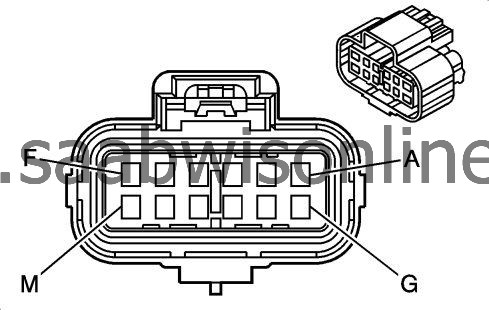
Connector Part Information
|
|||||||||||||||
Terminal Part Information
|
|||||||||||||||
K47 Rear Differential Clutch Control Module X1
| Pin | Wire Color | Circuit No. | Operation |
|
A
|
-
|
-
|
Not used
|
|
B
|
0.5 WH
|
6106
|
High Speed GMLAN Serial Data (-) (2)
|
|
C
|
-
|
-
|
Not used
|
|
D
|
0.5 WH
|
2501
|
High Speed GMLAN Serial Data (-) (1)
|
|
E
|
1 BK
|
2350
|
Ground
|
|
F
|
0.5 WH/BU
|
5986
|
Serial Data Communication Enable
|
|
G
|
-
|
-
|
Not used
|
|
H
|
0.5 BU
|
6105
|
High Speed GMLAN Serial Data (+) (2)
|
|
J
|
-
|
-
|
Not used
|
|
K
|
0.5 BU
|
2500
|
High Speed GMLAN Serial Data (+) (1)
|
|
L
|
1 BK
|
2350
|
Ground
|
|
M
|
1 RD/YE
|
640
|
Battery Positive Voltage
|
| K60 Steering Column Lock Control Module |
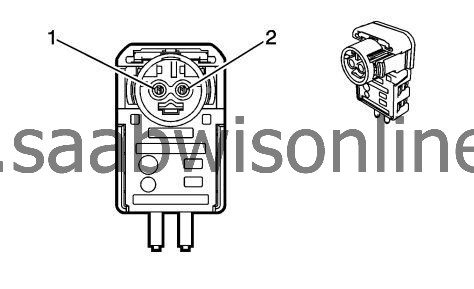
Connector Part Information
|
||||||||||||||||||||||||
Terminal Part Information
|
||||||||||||||||||||||||
K60 Steering Column Lock Control Module
| Pin | Wire Color | Circuit No. | Operation |
|
1
|
-
|
-
|
Not used
|
|
2
|
0.5 BU/VT
|
5904
|
Steering Column Lock Status Signal
|
|
3
|
1 BU/VT
|
807
|
OFF /Accessory Voltage
|
|
4
|
0.75 GN/VT
|
1601
|
Steering Column Lock Signal
|
|
5
|
1 RD/GY
|
1740
|
Battery Positive Voltage
|
|
6
|
1 BK
|
1550
|
Ground
|
|
7
|
0.5 BK/WH
|
1551
|
Signal Ground
|
|
8
|
0.5 GN
|
5060
|
Low Speed GMLAN Serial Data
|
| K62 Sunroof Sunshade Motor Module (C3U) |
Connector Part Information
|
||||||||||||||||||||||||
Terminal Part Information
|
||||||||||||||||||||||||
K62 Sunroof Sunshade Motor Module (C3U)
| Pin | Wire Color | Circuit No. | Operation |
|
1
|
2.5 RD/BU
|
840
|
Battery Positive Voltage
|
|
2
|
2.5 BK
|
3450
|
Ground
|
|
3
|
0.5 BK/BU
|
5307
|
Low Reference
|
|
4
|
0.5 GN/BN
|
6132
|
Linear Interconnect Network Bus 1
|
|
5
|
0.5 BU/GY
|
3032
|
Front Sunshade Switch Signal
|
|
6-8
|
-
|
-
|
Not used
|
|
9
|
0.5 BK
|
3350
|
Ground
|
|
10-12
|
-
|
-
|
Not used
|
| K65 Tire Pressure Indicator Module (UJN) |
Connector Part Information
|
|||||||||||||||||||||||||||
Terminal Part Information
|
|||||||||||||||||||||||||||
K65 Tire Pressure Indicator Module (UJN)
| Pin | Wire Color | Circuit No. | Operation |
|
1
|
0.5 BK/WH
|
2151
|
Signal Ground
|
|
2
|
0.75 RD/GY
|
2840
|
Battery Positive Voltage
|
|
2
|
0.75 RD/GY
|
2840
|
Battery Positive Voltage
|
|
3
|
0.5 GN/BU
|
6133
|
Linear Interconnect Network Bus 2
|
|
4
|
-
|
-
|
Not used
|
| K73 Telematics Communication Interface Control Module X1 (UE1) |
Connector Part Information
|
|||||||||||||||||||||||||||
Terminal Part Information
|
|||||||||||||||||||||||||||
K73 Telematics Communication Interface Control Module X1 (UE1)
| Pin | Wire Color | Circuit No. | Operation |
|
1
|
0.5 GN
|
5060
|
Low Speed GMLAN Serial Data
|
|
2
|
0.5 BN/WH
|
2517
|
Keypad Red LED
|
|
3
|
0.5 YE/VT
|
2516
|
Keypad Green LED
|
|
4-5
|
-
|
-
|
Not used
|
|
6
|
0.5 GN/BK
|
2515
|
Keypad Supply Voltage
|
|
7
|
0.75 BK
|
1750
|
Ground
|
|
8-9
|
-
|
-
|
Not used
|
|
10
|
0.5 BU
|
2500
|
High Speed GMLAN Serial Data (+) (1)
|
|
11
|
0.5 GN/WH
|
2514
|
Keypad Signal
|
|
12
|
0.5 WH
|
2501
|
High Speed GMLAN Serial Data (-) (1)
|
|
13
|
0.5 BK/VT
|
5167
|
Low Reference
|
|
14
|
0.5 YE/VT
|
5235
|
Battery Backup Supply Voltage
|
|
15
|
0.75 RD/GY
|
142
|
Battery Positive Voltage
|
|
16
|
-
|
-
|
Not used
|
| K73 Telematics Communication Interface Control Module X2 (UE1) |
Connector Part Information
|
||||||||||||
Terminal Part Information
|
||||||||||||
K73 Telematics Communication Interface Control Module X2 (UE1)
| Pin | Wire Color | Circuit No. | Operation |
|
1
|
0.5 YE
|
658
|
Cellular Telephone Voice Signal
|
|
2
|
0.5 BK/YE
|
659
|
Low Reference
|
|
3-4
|
-
|
-
|
Not used
|
|
5
|
0.5 BARE
|
1792
|
Drain Wire
|
|
6
|
0.5 GY/YE
|
5149
|
Voice Recognition Audio Signal
|
|
7
|
0.5 WH/BU
|
5986
|
Serial Data Communication Enable
|
|
8
|
0.5 BARE
|
1782
|
Drain Wire
|
|
9
|
0.5 BU
|
655
|
Cellular Telephone Microphone Signal
|
|
10
|
0.5 BARE
|
654
|
Low Reference
|
|
11
|
-
|
-
|
Not used
|
|
12
|
0.5 BK/GY
|
5152
|
Low Reference
|
| K74 Vehicle Direction Camera Control Module (UVT or UVL) |
Connector Part Information
|
||||||||||||||||||||||||
Terminal Part Information
|
||||||||||||||||||||||||
K74 Vehicle Direction Camera Control Module (UVT or UVL)
| Pin | Wire Color | Circuit No. | Operation |
|
1
|
0.5 BK/WH
|
2251
|
Signal Ground
|
|
2
|
0.5 BK/WH
|
2251
|
Signal Ground
|
|
3
|
0.75 RD/WH
|
1040
|
Battery Positive Voltage
|
|
4
|
0.5 WH
|
3152
|
Lane Departure Warning Indicator Control
|
|
5
|
0.5 BK/WH
|
2251
|
Signal Ground
|
|
6
|
-
|
-
|
Not used
|
|
7
|
0.5 GN
|
5060
|
Low Speed GMLAN Serial Data
|
|
8-9
|
-
|
-
|
Not used
|
|
10
|
0.5 GY/WH
|
3153
|
Lane Departure Warning Disable Switch Signal
|
| K77 Remote Control Door Lock Receiver |
Connector Part Information
|
||||||||||||
Terminal Part Information
|
||||||||||||
K77 Remote Control Door Lock Receiver
| Pin | Wire Color | Circuit No. | Operation |
|
1
|
0.5 GY
|
3273
|
Remote Function Actuator Return
|
|
2
|
0.5 YE/GN
|
3274
|
Remote Function Actuator Transmit Signal
|
|
3
|
0.5 BU/WH
|
3275
|
Remote Function Actuator Receive Signal
|
|
4
|
0.5 GY/WH
|
3272
|
Remote Function Actuator Supply Voltage
|
| K8 Blower Motor Control Module X2 |
Connector Part Information
|
||||||||||||||||||||||||
Terminal Part Information
|
||||||||||||||||||||||||
K8 Blower Motor Control Module X2
| Pin | Wire Color | Circuit No. | Operation |
|
1-2
|
-
|
-
|
Not used
|
|
3
|
0.5 BU/GY
|
754
|
Blower Motor Speed Control
|
|
4
|
-
|
-
|
Not used
|
|
5
|
6 BK
|
1950
|
Ground
|
|
6
|
6 RD/WH
|
1040
|
Battery Positive Voltage
|
| K82 Mobile Telephone Control Module X1 (UPH/UPJ) |
Connector Part Information
|
||||||||||||
Terminal Part Information
|
||||||||||||
K82 Mobile Telephone Control Module X1 (UPH/UPJ)
| Pin | Wire Color | Circuit No. | Operation |
|
1
|
0.75 RD/GN
|
3140
|
Battery Positive Voltage
|
|
2
|
0.75 BK
|
1750
|
Ground
|
|
3
|
0.35 YE
|
5169
|
Mid Speed GMLAN Serial Data (+)
|
|
4
|
0.35 WH
|
5170
|
Mid Speed GMLAN Serial Data (-)
|
|
5
|
0.5 BARE
|
1782
|
Drain Wire
|
|
6
|
0.5 YE
|
658
|
Cellular Telephone Voice Signal
|
|
7
|
0.5 BARE
|
1792
|
Drain Wire
|
|
8
|
0.5 BK/BN
|
654
|
Low Reference
|
|
9
|
0.5 BU
|
655
|
Cellular Telephone Microphone Signal
|
|
10-14
|
-
|
-
|
Not used
|
|
15
|
0.5 BK/YE
|
659
|
Low Reference
|
|
16
|
0.5 BARE
|
1792
|
Drain Wire
|
|
17
|
0.5 BK/GY
|
5152
|
Low Reference
|
|
18
|
0.5 GY/YE
|
5149
|
Voice Recognition Audio Signal
|
| K83 Parking Brake Control Module |
Connector Part Information
|
|||||||||||||||||||||||||||||||||||||||
Terminal Part Information
|
|||||||||||||||||||||||||||||||||||||||
K83 Parking Brake Control Module
| Pin | Wire Color | Circuit No. | Operation |
|
A
|
2.5 RD/WH
|
1040
|
Battery Positive Voltage
|
|
B
|
0.5 YE/RD
|
7683
|
Park Brake Release Switch Voltage Reference
|
|
C
|
0.5 BU/VT
|
1134
|
Park Brake Switch Signal
|
|
D
|
0.5 GY/RD
|
7684
|
Park Brake Apply Switch Voltage Reference
|
|
E
|
0.5 BU
|
2500
|
High Speed GMLAN Serial Data (+) (1)
|
|
F
|
0.5 BU
|
2500
|
High Speed GMLAN Serial Data (+) (1)
|
|
G
|
0.75 BU
|
2500
|
High Speed GMLAN Serial Data (+) (1)
|
|
G
|
0.5 BU
|
2500
|
High Speed GMLAN Serial Data (+) (1)
|
|
G
|
0.75 BU
|
2500
|
High Speed GMLAN Serial Data (+) (1)
|
|
G
|
0.5 BU
|
2500
|
High Speed GMLAN Serial Data (+) (1)
|
|
H
|
2.5 BK
|
3450
|
Ground
|
|
K
|
0.75 WH
|
2501
|
High Speed GMLAN Serial Data (-) (1)
|
|
K
|
0.5 WH
|
2501
|
High Speed GMLAN Serial Data (-) (1)
|
|
K
|
0.75 WH
|
2501
|
High Speed GMLAN Serial Data (-) (1)
|
|
K
|
0.5 WH
|
2501
|
High Speed GMLAN Serial Data (-) (1)
|
|
L
|
0.5 WH
|
2501
|
High Speed GMLAN Serial Data (-) (1)
|
|
M
|
0.5 WH
|
2501
|
High Speed GMLAN Serial Data (-) (1)
|
|
N
|
0.5 YE
|
1492
|
Park Brake Switch Supply Voltage
|
|
P
|
0.5 WH/BU
|
5986
|
Serial Data Communication Enable
|
|
R
|
0.5 BN
|
6107
|
Park Brake Apply Switch Signal
|
|
S
|
0.5 BU/BK
|
6108
|
Park Brake Release Switch Signal
|
| K84 Keyless Entry Control Module X1 |
Connector Part Information
|
||||||||||||||||||||||||
Terminal Part Information
|
||||||||||||||||||||||||
K84 Keyless Entry Control Module X1
| Pin | Wire Color | Circuit No. | Operation |
|
1
|
0.75 GN/VT
|
1601
|
Steering Column Lock Signal
|
|
2
|
-
|
-
|
Not used
|
|
3
|
0.5 GN
|
5060
|
Low Speed GMLAN Serial Data
|
|
4-8
|
-
|
-
|
Not used
|
|
9
|
0.5 WH/YE
|
3574
|
Driver Door Open Switch Signal
|
|
10
|
0.5 GY/GN
|
3575
|
Co_Driver Door Open Switch Signal
|
|
10
|
0.5 GY/GN
|
3575
|
Co_Driver Door Open Switch Signal
|
|
11
|
0.5 GN/BK
|
3558
|
Passive Start Switch Signal 2
|
|
12
|
0.5 BK/GY
|
3559
|
Low Reference
|
|
13-14
|
-
|
-
|
Not used
|
|
15
|
0.5 GY/BK
|
3555
|
Passive Start Interior Antenna 2 Signal Lo
|
|
16
|
0.5 BN/BK
|
3552
|
Passive Start Interior Antenna 1 Signal Hi
|
|
17
|
0.5 WH
|
3553
|
Passive Start Interior Antenna 1 Signal Lo
|
|
18
|
0.5 WH/GN
|
3556
|
Passive Start Interior Antenna 3 Signal Hi
|
|
19
|
0.5 GN
|
3557
|
Passive Start Interior Antenna 3 Signal Lo
|
|
20
|
0.5 BU
|
3554
|
Passive Start Interior Antenna 2 Signal Hi
|
| K84 Keyless Entry Control Module X2 |
Connector Part Information
|
|||||||||||||||||||||||||||
Terminal Part Information
|
|||||||||||||||||||||||||||
K84 Keyless Entry Control Module X2
| Pin | Wire Color | Circuit No. | Operation |
|
1
|
0.5 RD/VT
|
340
|
Battery Positive Voltage
|
|
2
|
1 BK/WH
|
2051
|
Signal Ground
|
|
3
|
0.5 VT/YE
|
4
|
Accessory Voltage
|
|
4
|
0.75 VT/BK
|
3
|
Run/Crank Ignition 1 Voltage
|
|
5
|
2.5 RD/VT
|
1940
|
Battery Positive Voltage
|
|
5
|
2.5 RD/GN
|
3140
|
Battery Positive Voltage
|
|
5
|
2.5 RD/VT
|
1940
|
Battery Positive Voltage
|
|
5
|
2.5 RD/GN
|
3140
|
Battery Positive Voltage
|
|
6
|
2.5 BK
|
2350
|
Ground
|
| K84 Keyless Entry Control Module X3 |
Connector Part Information
|
|||||||||||||||
Terminal Part Information
|
|||||||||||||||
K84 Keyless Entry Control Module X3
| Pin | Wire Color | Circuit No. | Operation |
|
1
|
-
|
-
|
Not used
|
|
2
|
0.75 GN/BK
|
6669
|
Right Rear Door Unlatch Motor Unlatch Control
|
|
3
|
0.75 BU/WH
|
6667
|
Left Rear Door Unlatch Motor Unlatch Control
|
|
4
|
1 YE/GN
|
3583
|
Co Driver Door Unlatch Motor Unlatch Control
|
|
4
|
1 YE/GN
|
3583
|
Co Driver Door Unlatch Motor Unlatch Control
|
|
5
|
1 VT/BU
|
6666
|
Driver Door Unlatch Motor Unlatch Control
|
|
5
|
1 VT/BU
|
6666
|
Driver Door Unlatch Motor Unlatch Control
|
|
6
|
-
|
-
|
Not used
|
|
7
|
0.75 GN/WH
|
3581
|
Right Rear Door Unlatch Motor Unlatch Return
|
|
8
|
0.75 BU/YE
|
3580
|
Left Rear Door Unlatch Motor Unlatch Return
|
|
9
|
1 GY/BK
|
3579
|
Co Driver Door Unlatch Motor Unlatch Return
|
|
9
|
1 GY/BK
|
3579
|
Co Driver Door Unlatch Motor Unlatch Return
|
|
10
|
1 GY
|
3578
|
Driver Door Unlatch Motor Unlatch Return
|
|
10
|
1 GY
|
3578
|
Driver Door Unlatch Motor Unlatch Return
|
| K84 Keyless Entry Control Module X4 |
Connector Part Information
|
||||||||||||
Terminal Part Information
|
||||||||||||
K84 Keyless Entry Control Module X4
| Pin | Wire Color | Circuit No. | Operation |
|
1
|
0.5 YE/GY
|
6158
|
Right Rear Door Handle Switch Signal
|
|
2
|
0.5 BN/YE
|
6157
|
Left Rear Door Handle Switch Signal
|
|
3
|
0.5 WH/BN
|
3572
|
Driver Door Unlatch Enable Signal
|
|
4
|
-
|
-
|
Not used
|
|
5
|
0.5 GY/BU
|
3576
|
Co-Driver Door Exterior Switch Lock Signal
|
|
5
|
0.5 GY/BU
|
3576
|
Co-Driver Door Exterior Switch Lock Signal
|
|
6
|
0.5 VT
|
3560
|
Passive Entry Driver Door Antenna Signal Hi
|
|
6
|
0.5 VT
|
3560
|
Passive Entry Driver Door Antenna Signal Hi
|
|
7
|
0.5 VT/GY
|
3561
|
Passive Entry Driver Door Antenna Signal Lo
|
|
7
|
0.5 VT/GY
|
3561
|
Passive Entry Driver Door Antenna Signal Lo
|
|
8
|
-
|
-
|
Not used
|
|
9
|
0.5 GN/BK
|
3563
|
Passive Entry Co_Driver Door Antenna Signal Lo
|
|
9
|
0.5 GN/BK
|
3563
|
Passive Entry Co_Driver Door Antenna Signal Lo
|
|
10
|
-
|
-
|
Not used
|
|
11
|
0.5 VT/WH
|
3571
|
Co_Driver Door Handle Switch Signal
|
|
11
|
0.5 VT/WH
|
3571
|
Co_Driver Door Handle Switch Signal
|
|
12
|
0.5 GN/WH
|
3570
|
Driver Door Handle Switch Signal
|
|
12
|
0.5 GN/WH
|
3570
|
Driver Door Handle Switch Signal
|
|
13
|
-
|
-
|
Not used
|
|
14
|
0.5 BU
|
3573
|
Non Driver Door Unlatch Enable Signal
|
|
15
|
0.5 GN/WH
|
6655
|
Driver Door Unlatch Switch Signal
|
|
15
|
0.5 GN/WH
|
6655
|
Driver Door Unlatch Switch Signal
|
|
16
|
0.5 BN/GN
|
3568
|
Passive Entry Rear Closure Antenna Signal Hi
|
|
17
|
-
|
-
|
Not used
|
|
18
|
0.5 GN/GY
|
3569
|
Passive Entry Rear Closure Antenna Signal Lo
|
|
19
|
-
|
-
|
Not used
|
|
20
|
0.5 GN/YE
|
3562
|
Passive Entry Co_Driver Door Antenna Signal Hi
|
|
20
|
0.5 GN/YE
|
3562
|
Passive Entry Co_Driver Door Antenna Signal Hi
|
| K89 Immobilizer Control Module |
Connector Part Information
|
|||||||||||||||
Terminal Part Information
|
|||||||||||||||
K89 Immobilizer Control Module
| Pin | Wire Color | Circuit No. | Operation |
|
1
|
0.5 GN/GY
|
3277
|
Vehicle Anti-Theft System Immobilizer Return
|
|
2
|
0.35 GN/VT
|
7533
|
Linear Interconnect Network Bus 11
|
|
3
|
0.5 GY/BK
|
3276
|
Vehicle Anti-Theft System Immobilizer Supply Voltage
|
| K8A Blower Motor Control Module - Auxiliary (CJ4) |
Connector Part Information
|
||||||||||||
Terminal Part Information
|
||||||||||||
K8A Blower Motor Control Module - Auxiliary (CJ4)
| Pin | Wire Color | Circuit No. | Operation |
|
1
|
0.5 GN/BK
|
2211
|
Rear Blower Motor Speed Control
|
|
2
|
1 RD/BN
|
2240
|
Battery Positive Voltage
|
|
3
|
-
|
-
|
Not used
|
|
4
|
1 BK
|
2150
|
Ground
|
| K9 Body Control Module X1 |
Connector Part Information
|
||||||||||||||||||||||||
Terminal Part Information
|
||||||||||||||||||||||||
K9 Body Control Module X1
| Pin | Wire Color | Circuit No. | Operation |
|
1
|
1.5 BK
|
1850
|
Ground
|
|
2
|
1.5 OG/BK
|
974
|
Battery Positive Voltage
|
|
3
|
1.5 GY
|
1524
|
Backup Lamp Supply Voltage Signal
|
|
4
|
1.5 BN
|
6136
|
Supply Voltage
|
|
5
|
0.5 WH
|
6816
|
Indicator Dimming Control
|
|
6
|
0.5 YE
|
7554
|
Park Lock Solenoid Soft Control
|
|
7
|
-
|
-
|
Not used
|
|
8
|
0.35 BN/BK
|
5720
|
Ignition Mode Switch Accessory LED Signal
|
|
9
|
0.5 WH/BN
|
7555
|
Lighting Control Switch Signal
|
|
10
|
-
|
-
|
Not used
|
|
11
|
0.35 GN/BN
|
306
|
Headlamp Switch Headlamps Off Signal Control
|
|
12-13
|
-
|
-
|
Not used
|
|
14
|
0.5 GY/GN
|
328
|
Interior Lamp Defeat Switch Signal
|
|
15
|
0.5 WH/VT
|
6821
|
Surveillance Switch Signal
|
|
16
|
0.35 WH/VT
|
103
|
Headlamp Switch On Signal
|
|
17
|
0.35 GY/YE
|
7543
|
Hazard LED Dimming Signal
|
|
18
|
-
|
-
|
Not used
|
|
19
|
0.5 BK/BN
|
5360
|
Low Reference
|
|
20
|
0.5 BU/BK
|
5719
|
Ignition Mode Switch Start LED Signal
|
|
21
|
0.35 GY
|
728
|
Security Indicator Control
|
|
22
|
0.35 GN/GY
|
13
|
Headlamp Switch Park Lamp Signal
|
|
23
|
0.5 WH/YE
|
7557
|
LED Ambient Lighting Control 1
|
|
23
|
0.5 WH/YE
|
7557
|
LED Ambient Lighting Control 1
|
|
24
|
0.5 WH
|
2501
|
High Speed GMLAN Serial Data (-) (1)
|
|
25
|
0.5 BU
|
2500
|
High Speed GMLAN Serial Data (+) (1)
|
|
26
|
0.5 BU/WH
|
3275
|
Remote Function Actuator Receive Signal
|
| K9 Body Control Module X2 |
Connector Part Information
|
||||||||||||||||||||||||||||||||||||||||||||||||
Terminal Part Information
|
||||||||||||||||||||||||||||||||||||||||||||||||
K9 Body Control Module X2
| Pin | Wire Color | Circuit No. | Operation |
|
1
|
1.5 RD/GY
|
2140
|
Battery Positive Voltage
|
|
2
|
0.75 BK
|
1650
|
Ground
|
|
3
|
2.5 GY
|
975
|
Battery Positive Voltage
|
|
4
|
2.5 RD/BN
|
1440
|
Battery Positive Voltage
|
|
5
|
0.5 GY
|
157
|
Interior Lamp Control
|
|
6
|
0.5 GY
|
5697
|
Child Lockout Indicator
|
|
7
|
0.5 BU/YE
|
5361
|
Brake Apply Sensor Signal
|
|
8
|
0.5 YE
|
6817
|
LED Backlight Dimming Control
|
|
9
|
-
|
-
|
Not used
|
|
10
|
0.35 WH/BU
|
278
|
Ambient Light Sensor Signal
|
|
11
|
0.5 VT/YE
|
5526
|
Tap Up/Tap Down Switch Signal
|
|
12
|
-
|
-
|
Not used
|
|
13
|
0.5 WH
|
5359
|
Brake Apply Sensor Supply Voltage
|
|
14
|
0.5 BU/VT
|
1788
|
Traction Control Switch Signal (1)
|
|
15
|
-
|
-
|
Not used
|
|
16
|
0.5 GY
|
3273
|
Remote Function Actuator Return
|
|
17
|
0.5 BU/GN
|
5723
|
Ignition Mode Switch Mode Voltage
|
|
18
|
0.5 YE/BN
|
3265
|
Child Security Lock Switch Signal
|
|
19
|
0.5 BU/VT
|
5904
|
Steering Column Lock Status Signal
|
|
20
|
-
|
-
|
Not used
|
|
21
|
0.5 GN/GY
|
6135
|
Linear Interconnect Network Bus 4
|
|
22
|
0.5 GN
|
5060
|
Low Speed GMLAN Serial Data
|
|
23
|
0.5 WH
|
2501
|
High Speed GMLAN Serial Data (-) (1)
|
|
24
|
0.5 BU
|
2500
|
High Speed GMLAN Serial Data (+) (1)
|
|
25
|
0.5 GY/WH
|
3272
|
Remote Function Actuator Supply Voltage
|
|
26
|
0.35 GN/WH
|
111
|
Hazard Switch Signal
|
|
27
|
0.5 YE/GN
|
3274
|
Remote Function Actuator Transmit Signal
|
| K9 Body Control Module X3 |
Connector Part Information
|
||||||||||||
Terminal Part Information
|
||||||||||||
K9 Body Control Module X3
| Pin | Wire Color | Circuit No. | Operation |
|
1
|
0.5 GN/GY
|
3277
|
Vehicle Anti-Theft System Immobilizer Return
|
|
2
|
0.35 GN/VT
|
7533
|
Linear Interconnect Network Bus 11
|
|
3
|
0.5 GY/BK
|
3276
|
Vehicle Anti-Theft System Immobilizer Supply Voltage
|
|
4
|
0.5 YE
|
7556
|
Lighting Control Switch Reference
|
|
4
|
0.5 YE
|
7556
|
Lighting Control Switch Reference
|
|
5
|
0.5 VT/YE
|
4
|
Accessory Voltage
|
|
6
|
0.5 VT/BK
|
3
|
Run/Crank Ignition 1 Voltage
|
|
7
|
-
|
-
|
Not used
|
|
8
|
0.5 GN
|
6818
|
Steering Wheel Resistor Ladder Signal #1
|
|
9
|
0.5 BN/GN
|
1884
|
Cruise Control Set/Coast/Resume/Accelerate Switch Signal
|
|
10
|
0.5 BK/GY
|
6009
|
Low Reference
|
|
11
|
0.5 WH
|
524
|
Headlamp Dimmer Switch High Beam Signal
|
|
12
|
0.5 WH/GN
|
663
|
Hazard Switch Left Turn Signal
|
|
13
|
0.5 YE/BU
|
1714
|
Windshield Wiper Switch Low Signal
|
|
14
|
0.5 BU/GY
|
553
|
Shift Select Switch Performance Signal
|
|
15
|
-
|
-
|
Not used
|
|
16
|
0.5 GY/GN
|
5737
|
Adaptive Cruise Control Gap Up/Down Switch Signal
|
|
17
|
0.5 YE/BN
|
307
|
Headlamp Switch Flash To Pass Signal
|
|
18
|
0.5 BN/WH
|
28
|
Horn Relay Control
|
|
19
|
-
|
-
|
Not used
|
|
20
|
0.5 GY
|
1715
|
Windshield Wiper Switch High Signal
|
|
21
|
0.5 VT/YE
|
5526
|
Tap Up/Tap Down Switch Signal
|
|
22-23
|
-
|
-
|
Not used
|
|
24
|
0.5 VT/BU
|
664
|
Hazard Switch Right Turn Signal
|
|
25
|
0.5 WH/BK
|
94
|
Windshield Washer Switch Signal
|
| K9 Body Control Module X4 |
Connector Part Information
|
|||||||||||||||||||||||||||||||||||||||
Terminal Part Information
|
|||||||||||||||||||||||||||||||||||||||
K9 Body Control Module X4
| Pin | Wire Color | Circuit No. | Operation |
|
1
|
1 YE
|
312
|
Right Headlamp Low Beam Supply Voltage
|
|
1
|
1 BU/BN
|
7539
|
Right Front DRL Supply Voltage
|
|
2
|
1 YE
|
712
|
Left Headlamp Low Beam Supply Voltage
|
|
2
|
1 GY/BU
|
7538
|
Left Front DRL Supply Voltage
|
|
2
|
1 GY/BU
|
7538
|
Left Front DRL Supply Voltage
|
|
3
|
0.75 GN/VT
|
1315
|
Right Front Turn Signal Lamp Supply Voltage
|
|
4
|
0.75 BU/VT
|
1335
|
Right Rear Turn Signal Lamp Supply Voltage
|
|
4
|
0.75 BU/VT
|
1335
|
Right Rear Turn Signal Lamp Supply Voltage
|
|
5
|
0.5 GY/BN
|
309
|
Right Park Lamp Supply Voltage
|
|
6
|
0.5 VT/GY
|
709
|
Left Park Lamp Supply Voltage
|
|
7
|
0.5 GY/YE
|
7542
|
Left Rear Stop Lamp Supply Voltage
|
|
8
|
-
|
-
|
Not used
|
|
9
|
0.5 GY/VT
|
3264
|
Logistic Mode Relay Close Control
|
|
9
|
0.5 GY/VT
|
3264
|
Logistic Mode Relay Close Control
|
|
10
|
-
|
-
|
Not used
|
|
11
|
0.5 VT/WH
|
5065
|
Stop Lamp Relay Coil Supply Voltage
|
|
12
|
0.5 VT
|
801
|
Retained Accessory Power Fuse Supply Voltage
|
|
13
|
0.5 GN/YE
|
6846
|
Rear License Lamp Supply Voltage
|
|
14
|
0.5 BN/GY
|
2268
|
Windshield Washer Relay Control
|
|
15
|
0.5 GN/VT
|
5199
|
Run/Crank Relay Coil Control
|
|
16
|
0.5 GY
|
91
|
Windshield Wiper Motor Relay Coil Supply Voltage
|
|
17
|
0.5 BN/GN
|
196
|
Windshield Wiper Motor Park Switch Signal
|
|
17
|
0.5 BN/GN
|
196
|
Windshield Wiper Motor Park Switch Signal
|
|
18
|
0.5 WH/YE
|
5075
|
Current Sensor Signal
|
|
19
|
-
|
-
|
Not used
|
|
20
|
0.5 RD/YE
|
1442
|
Battery Positive Voltage
|
|
21
|
0.5 BU/VT
|
5076
|
Current Sensor Supply Voltage
|
|
22
|
0.5 VT/YE
|
5985
|
Accessory Wake Up Serial Data
|
|
23
|
0.5 WH/BU
|
5986
|
Serial Data Communication Enable
|
|
24
|
0.5 BN/GN
|
109
|
Hood Ajar Switch Signal
|
|
24
|
0.5 BN/GN
|
109
|
Hood Ajar Switch Signal
|
|
25
|
-
|
-
|
Not used
|
|
26
|
0.5 BK
|
50
|
Ground
|
| K9 Body Control Module X5 |
Connector Part Information
|
||||||||||||||||||||||||||||||||||||||||||||||||
Terminal Part Information
|
||||||||||||||||||||||||||||||||||||||||||||||||
K9 Body Control Module X5
| Pin | Wire Color | Circuit No. | Operation |
|
1
|
0.75 BU/WH
|
1334
|
Left Rear Turn Signal Lamp Supply Voltage
|
|
1
|
0.75 BU/WH
|
1334
|
Left Rear Turn Signal Lamp Supply Voltage
|
|
2
|
0.75 BU/WH
|
1314
|
Left Front Turn Signal Lamp Supply Voltage
|
|
3
|
1.5 GY/VT
|
691
|
Headlamp Low Beam Relay Control
|
|
4
|
2.5 GN/GY
|
9
|
Park Lamp Supply Voltage
|
|
5
|
0.5 BN/BU
|
1977
|
Rear Fog Lamp Relay Control
|
|
6
|
0.5 BK/VT
|
5077
|
Low Reference
|
|
7
|
0.5 WH/YE
|
7541
|
Right Rear Stop Lamp Supply Voltage
|
|
8
|
0.5 YE
|
9382
|
Transmission Sport Mode Indicator Control
|
|
9
|
-
|
-
|
Not used
|
|
10
|
0.5 BN/WH
|
1317
|
Fog Lamp Relay Control
|
|
11
|
0.5 GY/YE
|
6188
|
Lift Glass/Trunk Motor Release Control
|
|
12
|
0.5 WH/BU
|
6311
|
Cruise/ETC/TCC Brake Signal
|
|
13
|
0.5 BN/YE
|
1970
|
Headlamp Low Beam Relay Control
|
|
14
|
0.5 BN/VT
|
5486
|
Run Relay Coil Control
|
|
15
|
-
|
-
|
Not used
|
|
16
|
0.5 VT/YE
|
3267
|
Child Security Lock Relay Control
|
|
17
|
0.5 YE
|
9381
|
Transmission Intelligent Mode Indicator Control
|
|
18
|
0.5 BN/VT
|
1969
|
Headlamp High Beam Relay Control
|
|
19
|
0.5 BN/WH
|
28
|
Horn Relay Control
|
|
20
|
0.5 YE
|
9383
|
Transmission Comfort Mode Indicator Control
|
|
21-23
|
-
|
-
|
Not used
|
|
24
|
0.5 WH/VT
|
860
|
Front Windshield Wiper Switch High Signal
|
|
25
|
-
|
-
|
Not used
|
|
26
|
0.5 YE/BU
|
2282
|
Headlamp Washer Relay Control
|
| K9 Body Control Module X6 |
Connector Part Information
|
||||||||||||||||||||||||||||||||||||||||||||||||
Terminal Part Information
|
||||||||||||||||||||||||||||||||||||||||||||||||
K9 Body Control Module X6
| Pin | Wire Color | Circuit No. | Operation |
|
1
|
1 BU/WH
|
195
|
Door Lock Control
|
|
1
|
2.5 GY
|
5911
|
Door Double Lock Actuator Lock Control 2
|
|
2
|
2.5 GY/GN
|
3271
|
Door Lock Control (2)
|
|
3
|
2.5 BK
|
2150
|
Ground
|
|
4
|
2.5 BN/YE
|
294
|
Door Lock Actuator Unlock Control
|
|
5
|
0.5 VT/GY
|
1303
|
Lift Gate Ajar Switch Signal (1)
|
|
6-8
|
-
|
-
|
Not used
|
|
9
|
0.5 GN/BU
|
6133
|
Linear Interconnect Network Bus 2
|
|
10
|
0.5 GN/YE
|
6134
|
Linear Interconnect Network Bus 3
|
|
11-14
|
-
|
-
|
Not used
|
|
15
|
0.5 YE/BU
|
5797
|
Rear Closure Handle Switch Open Signal
|
|
16
|
0.5 GN/BN
|
6132
|
Linear Interconnect Network Bus 1
|
|
16
|
0.5 GN/BN
|
6132
|
Linear Interconnect Network Bus 1
|
|
17-21
|
-
|
-
|
Not used
|
|
22
|
0.5 GY
|
5054
|
Sport Mode Switch Signal
|
|
23
|
0.5 GN/BU
|
6133
|
Linear Interconnect Network Bus 2
|
|
24
|
0.5 BU
|
2500
|
High Speed GMLAN Serial Data (+) (1)
|
|
25
|
0.5 WH
|
2501
|
High Speed GMLAN Serial Data (-) (1)
|
|
26-27
|
-
|
-
|
Not used
|
| K9 Body Control Module X7 |
Connector Part Information
|
|||||||||||||||||||||||||||||||||||||||
Terminal Part Information
|
|||||||||||||||||||||||||||||||||||||||
K9 Body Control Module X7
| Pin | Wire Color | Circuit No. | Operation |
|
1
|
0.75 GY
|
157
|
Interior Lamp Control
|
|
2
|
1 WH/BN
|
6815
|
Inadvertent Power Control
|
|
3
|
0.75 GN/WH
|
24
|
Backup Lamp Supply Voltage
|
|
3
|
0.75 GN/WH
|
24
|
Backup Lamp Supply Voltage
|
|
4
|
0.5 BU/BN
|
7547
|
Security Lock Relay Control
|
|
5
|
0.5 WH/BN
|
3572
|
Driver Door Unlatch Enable Signal
|
|
6
|
0.5 VT/BK
|
7553
|
Park Lock Solenoid Control
|
|
7
|
0.5 GN/GY
|
737
|
Trunk Lamp Control
|
|
8
|
0.5 GY/GN
|
5996
|
Driver Outside Rear View Mirror Puddle Lamp Supply Voltage
|
|
9
|
0.5 YE
|
6817
|
LED Backlight Dimming Control
|
|
10
|
0.5 BN/YE
|
186
|
Fuel Door Lock Relay Control
|
|
11
|
-
|
-
|
Not used
|
|
12
|
0.5 BN/YE
|
780
|
Driver Door Lock Switch Lock Signal
|
|
13
|
0.5 WH/VT
|
5905
|
Key Capture/Column Lock Shift Position Signal
|
|
14
|
0.5 GY/BK
|
3268
|
Child Security Lock Motor Status Signal Right Rear
|
|
15
|
-
|
-
|
Not used
|
|
16
|
0.5 VT/BU
|
3263
|
Logistic Mode Relay Open Control
|
|
16
|
0.5 VT/BU
|
3263
|
Logistic Mode Relay Open Control
|
|
17
|
0.5 BU
|
3573
|
Non Driver Door Unlatch Enable Signal
|
|
18
|
0.5 BN/WH
|
781
|
Driver Door Lock Switch Unlock Signal
|
|
19
|
0.5 GY
|
156
|
Courtesy Lamp Switch Signal
|
|
20-21
|
-
|
-
|
Not used
|
|
22
|
0.5 GN/BU
|
5721
|
Ignition Mode Switch Off LED Signal
|
|
23
|
0.5 GN
|
5060
|
Low Speed GMLAN Serial Data
|
|
24
|
-
|
-
|
Not used
|
|
25
|
0.5 BN/WH
|
3269
|
Child Security Lock Motor Status Signal Left Rear
|
|
26
|
-
|
-
|
Not used
|
| M13 Door Latch Assembly - Rear Cargo |
Connector Part Information
|
||||||||||||
Terminal Part Information
|
||||||||||||
M13 Door Latch Assembly - Rear Cargo
| Pin | Wire Color | Circuit No. | Operation |
|
1
|
0.75 BU/YE
|
6795
|
Lift Glass/Trunk Motor Release Control 2
|
|
2
|
1 BK
|
3350
|
Ground
|
|
3
|
-
|
-
|
Not used
|
|
4
|
0.5 VT/GY
|
1303
|
Lift Gate Ajar Switch Signal (1)
|
| M27 Fuel Door Unlatch Actuator |
Connector Part Information
|
||||||||||||
Terminal Part Information
|
||||||||||||
M27 Fuel Door Unlatch Actuator
| Pin | Wire Color | Circuit No. | Operation |
|
1
|
0.75 BN/YE
|
294
|
Door Lock Actuator Unlock Control
|
|
1
|
0.75 BN/YE
|
294
|
Door Lock Actuator Unlock Control
|
|
2
|
0.75 BU
|
6800
|
Fuel Door Lock/Unlock (1) Signal
|
|
2
|
0.75 GY
|
5911
|
Door Double Lock Actuator Lock Control 2
|
|
2
|
0.75 BU
|
6800
|
Fuel Door Lock/Unlock (1) Signal
|
|
2
|
0.75 GY
|
5911
|
Door Double Lock Actuator Lock Control 2
|
| M64 Starter Motor X1 |
Connector Part Information
|
||||||||||||
Terminal Part Information
|
||||||||||||
M64 Starter Motor X1
| Pin | Wire Color | Circuit No. | Operation |
|
A
|
35 BK
|
150
|
Ground
|
| M64 Starter Motor X2 (LAU) |
Connector Part Information
|
||||||||||||
Terminal Part Information
|
||||||||||||
M64 Starter Motor X2 (LAU)
| Pin | Wire | Circuit | Operation |
|
1
|
2.5 YE
|
6
|
Starter Solenoid Crank Voltage
|
| M64 Starter Motor X2 (LBS) |
Connector Part Information
|
||||||||||||
Terminal Part Information
|
||||||||||||
M64 Starter Motor X2 (LBS)
| Pin | Wire | Circuit | Operation |
|
1
|
2.5 YE
|
6
|
Starter Solenoid Crank Voltage
|
| M64 Starter Motor X2 (LDK) |
Connector Part Information
|
||||||||||||
Terminal Part Information
|
||||||||||||
M64 Starter Motor X2 (LDK)
| Pin | Wire | Circuit | Operation |
|
A
|
2.5 YE
|
6
|
Starter Solenoid Crank Voltage
|
| M69 Sunroof Motor (C3U) |
Connector Part Information
|
||||||||||||||||||||||||
Terminal Part Information
|
||||||||||||||||||||||||
M69 Sunroof Motor (C3U)
| Pin | Wire Color | Circuit No. | Operation |
|
1
|
2.5 RD/GN
|
742
|
Battery Positive Voltage
|
|
2
|
2.5 BK
|
2150
|
Ground
|
|
3
|
0.5 BK/GY
|
128
|
Low Reference
|
|
4
|
0.5 GN/BN
|
6132
|
Linear Interconnect Network Bus 1
|
|
5
|
0.5 BU/VT
|
5027
|
Sunroof Switch Data (1)
|
|
8
|
0.5 BK
|
2250
|
Ground
|
| M72 Variable Power Steering Solenoid Valve |
Connector Part Information
|
||||||||||||
Terminal Part Information
|
||||||||||||
M72 Variable Power Steering Solenoid Valve
| Pin | Wire Color | Circuit No. | Operation |
|
1
|
0.5 BN
|
1295
|
Variable Effort Steering Solenoid Control
|
|
2
|
0.5 YE
|
6641
|
Low Reference
|
| M74D Window Motor - Driver |
Connector Part Information
|
||||||||||||||||||||||||
Terminal Part Information
|
||||||||||||||||||||||||
M74D Window Motor - Driver
| Pin | Wire Color | Circuit No. | Operation |
|
1
|
2.5 BK
|
1550
|
Ground
|
|
2
|
2.5 RD/GN
|
1540
|
Battery Positive Voltage
|
|
3
|
0.5 GN/WH
|
3379
|
Power Window Switch Driver Up Signal
|
|
3
|
0.5 YE/BK
|
3384
|
Power Window Switch Co-Driver Up Signal
|
|
4
|
0.5 GN/YE
|
6134
|
Linear Interconnect Network Bus 3
|
|
5
|
0.5 GN
|
3381
|
Power Window Switch Driver Express Signal
|
|
5
|
0.5 VT/GY
|
3386
|
Power Window Switch Co-Driver Express Signal
|
|
6
|
0.5 GY
|
745
|
Left Front Door Ajar Switch Signal
|
|
7
|
0.5 GY
|
3380
|
Power Window Switch Driver Down Signal
|
|
7
|
0.5 BN/YE
|
3385
|
Power Window Switch Driver Down Signal
|
| M74LR Window Motor - Left Rear (AEQ) |
Connector Part Information
|
||||||||||||
Terminal Part Information
|
||||||||||||
M74LR Window Motor - Left Rear (AEQ)
| Pin | Wire Color | Circuit No. | Operation |
|
A
|
2.5 YE/BU
|
669
|
Power Window Motor Left Rear Down Control
|
|
B
|
2.5 BU/VT
|
668
|
Power Window Motor Left Rear Up Control
|
| M74LR Window Motor - Left Rear (AER) |
Connector Part Information
|
||||||||||||||||||||||||
Terminal Part Information
|
||||||||||||||||||||||||
M74LR Window Motor - Left Rear (AER)
| Pin | Wire Color | Circuit No. | Operation |
|
1
|
2.5 BK
|
2350
|
Ground
|
|
2
|
2.5 RD/BN
|
2940
|
Battery Positive Voltage
|
|
3
|
0.5 GN/GY
|
1185
|
Power Window Switch Left Rear Up Signal
|
|
4
|
0.5 GN/GY
|
6135
|
Linear Interconnect Network Bus 4
|
|
5
|
0.5 GY/GN
|
5048
|
Power Window Switch Left Rear Express Signal
|
|
6
|
0.5 GY
|
747
|
Left Rear Door Ajar Switch Signal
|
|
7
|
0.5 BN/BU
|
1187
|
Power Window Switch Left Rear Down Signal
|
| M74P Window Motor - Passenger |
Connector Part Information
|
||||||||||||||||||||||||
Terminal Part Information
|
||||||||||||||||||||||||
M74P Window Motor - Passenger
| Pin | Wire Color | Circuit No. | Operation |
|
1
|
2.5 BK
|
2050
|
Ground
|
|
2
|
2.5 RD/GN
|
1540
|
Battery Positive Voltage
|
|
3
|
0.5 GN/WH
|
3379
|
Power Window Switch Driver Up Signal
|
|
3
|
0.5 YE/BK
|
3384
|
Power Window Switch Co-Driver Up Signal
|
|
4
|
0.5 GN/YE
|
6134
|
Linear Interconnect Network Bus 3
|
|
5
|
0.5 GN
|
3381
|
Power Window Switch Driver Express Signal
|
|
5
|
0.5 VT/GY
|
3386
|
Power Window Switch Co-Driver Express Signal
|
|
6
|
0.5 GY
|
746
|
Right Front Door Ajar Switch Signal
|
|
7
|
0.5 GY
|
3380
|
Power Window Switch Driver Down Signal
|
|
7
|
0.5 BN/YE
|
3385
|
Power Window Switch Driver Down Signal
|
| M74RR Window Motor - Right Rear (AEQ) |
Connector Part Information
|
||||||||||||
Terminal Part Information
|
||||||||||||
M74RR Window Motor - Right Rear (AEQ)
| Pin | Wire Color | Circuit No. | Operation |
|
A
|
2.5 GN/BK
|
671
|
Power Window Motor Right Rear Down Control
|
|
B
|
2.5 BU/GY
|
670
|
Power Window Motor Right Rear Up Control
|
| M74RR Window Motor - Right Rear (AER) |
Connector Part Information
|
||||||||||||||||||||||||
Terminal Part Information
|
||||||||||||||||||||||||
M74RR Window Motor - Right Rear (AER)
| Pin | Wire Color | Circuit No. | Operation |
|
1
|
2.5 BK
|
2050
|
Ground
|
|
2
|
2.5 RD/BN
|
2940
|
Battery Positive Voltage
|
|
3
|
0.5 GN/GY
|
1186
|
Power Window Switch Right Rear Up Signal
|
|
4
|
0.5 GN/GY
|
6135
|
Linear Interconnect Network Bus 4
|
|
5
|
0.5 WH/GN
|
5049
|
Power Window Switch Right Rear Express Signal
|
|
6
|
0.5 GY
|
748
|
Right Rear Door Ajar Switch Signal
|
|
7
|
0.5 BN/BU
|
1188
|
Power Window Switch Right Rear Down Signal
|
| M75 Windshield Wiper Motor |
Connector Part Information
|
||||||||||||||||||||||||
Terminal Part Information
|
||||||||||||||||||||||||
M75 Windshield Wiper Motor
| Pin | Wire Color | Circuit No. | Operation |
|
A
|
2.5 BK
|
1450
|
Ground
|
|
A
|
2.5 BK
|
1050
|
Ground
|
|
B
|
0.5 BN/GN
|
196
|
Windshield Wiper Motor Park Switch Signal
|
|
B
|
0.5 BN/GN
|
196
|
Windshield Wiper Motor Park Switch Signal
|
|
C
|
2.5 WH
|
92
|
Windshield Wiper Motor High Speed Control
|
|
C
|
2.5 WH
|
92
|
Windshield Wiper Motor High Speed Control
|
|
D
|
2.5 YE/BN
|
95
|
Windshield Wiper Motor Low Speed Control
|
|
D
|
2.5 YE/BN
|
95
|
Windshield Wiper Motor Low Speed Control
|
| M9 Brake Booster Pump Motor |
Connector Part Information
|
||||||||||||
Terminal Part Information
|
||||||||||||
M9 Brake Booster Pump Motor
| Pin | Wire Color | Circuit No. | Operation |
|
1
|
2.5 BK
|
1450
|
Ground
|
|
2
|
0.5 BN
|
6305
|
Brake Vacuum Switch Signal
|
|
5
|
2.5 RD/VT
|
1940
|
Battery Positive Voltage
|
| M9 Brake Booster Pump Motor (LAU) |
Connector Part Information
|
||||||||||||
Terminal Part Information
|
||||||||||||
M9 Brake Booster Pump Motor (LAU)
| Pin | Wire Color | Circuit No. | Operation |
|
1
|
2.5 BK
|
1050
|
Ground
|
|
2
|
0.5 BN
|
6305
|
Brake Vacuum Switch Signal
|
|
5
|
2.5 RD/VT
|
1940
|
Battery Positive Voltage
|
| P12 Horn |
Connector Part Information
|
||||||||||||
Terminal Part Information
|
||||||||||||
P12 Horn
| Pin | Wire Color | Circuit No. | Operation |
|
1
|
1 BK
|
1750
|
Ground
|
|
1
|
1 BK
|
1350
|
Ground
|
|
2
|
1 BN/GY
|
29
|
Horn Control
|
|
2
|
1 BN/GY
|
29
|
Horn Control
|
| P16 Instrument Cluster |
Connector Part Information
|
||||||||||||
Terminal Part Information
|
||||||||||||
P16 Instrument Cluster
| Pin | Wire Color | Circuit No. | Operation |
|
1
|
0.5 GN
|
5060
|
Low Speed GMLAN Serial Data
|
|
2
|
0.5 GN
|
5060
|
Low Speed GMLAN Serial Data
|
|
3
|
-
|
-
|
Not used
|
|
4
|
0.35 GN/WH
|
1358
|
Driver Information Center Switch Signal
|
|
5
|
0.35 BK/BN
|
897
|
Low Reference
|
|
6
|
0.5 BK/BU
|
61
|
Outside Ambient Temperature Sensor Low Reference
|
|
7
|
0.5 BU/GY
|
636
|
Outside Ambient Air Temperature Sensor Signal
|
|
8
|
-
|
-
|
Not used
|
|
9
|
0.5 GN/YE
|
1478
|
Coolant Level Switch Signal
|
|
10
|
0.5 BK
|
1850
|
Ground
|
|
11-14
|
-
|
-
|
Not used
|
|
15
|
0.5 VT
|
185
|
Low Washer Fluid Indicator Control
|
|
16
|
0.35 GY/BU
|
893
|
Driver Information Center Select Menu Switch Signal
|
|
17
|
0.5 BN/WH
|
419
|
Check Engine Indicator Control
|
|
18
|
-
|
-
|
Not used
|
|
19
|
0.35 VT/GY
|
139
|
Run/Crank Ignition 1 Voltage
|
|
20
|
0.5 RD/GY
|
142
|
Battery Positive Voltage
|
| P17 Info Display Module X1 (UAG) |
Connector Part Information
|
||||||||||||
Terminal Part Information
|
||||||||||||
P17 Info Display Module X1 (UAG)
| Pin | Wire Color | Circuit No. | Operation |
|
1
|
0.5 RD/GN
|
3140
|
Battery Positive Voltage
|
|
2
|
0.5 BK
|
1750
|
Ground
|
|
3
|
0.5 GN/BU
|
7532
|
Linear Interconnect Network Bus 10
|
|
4
|
0.35 GY/GN
|
3291
|
Integrated Center Stack Wake Up Signal
|
|
5
|
0.35 VT
|
3290
|
Integrated Center Stack Reset Signal
|
|
6
|
0.35 BARE
|
7460
|
Integrated Center Stack Serial Data Shield
|
|
7
|
0.35 VT
|
7458
|
Center Integrated Center Stack Serial Data High
|
|
8
|
0.35 YE
|
7459
|
Integrated Center Stack Serial Data Low
|
| P17 Info Display Module X1 (UDT) |
Connector Part Information
|
||||||||||||
Terminal Part Information
|
||||||||||||
P17 Info Display Module X1 (UDT)
| Pin | Wire Color | Circuit No. | Operation |
|
1
|
0.5 RD/GN
|
3140
|
Battery Positive Voltage
|
|
2
|
0.5 BK
|
1750
|
Ground
|
|
4
|
0.35 GY
|
3369
|
Touch Screen Display Signal (+)
|
|
5
|
0.5 BN/GN
|
3364
|
Navigation Display Reset Signal
|
|
6
|
0.5 GN/YE
|
7066
|
Entertainment Remote Enable Signal
|
|
7
|
0.35 BARE
|
3368
|
Touch Screen Display Drain Wire
|
|
8
|
0.35 VT
|
3370
|
Touch Screen Display Signal (-)
|
| P19A Speaker - Center Console |
Connector Part Information
|
||||||||||||
Terminal Part Information
|
||||||||||||
P19A Speaker - Center Console
| Pin | Wire Color | Circuit No. | Operation |
|
1
|
1 BN/BU
|
118
|
Left Front Speaker Signal (-) (1)
|
|
2
|
1 YE
|
200
|
Right Front Speaker (+) (1)
|
| P19AA Speaker - Right Subwoofer (UQS) |
Connector Part Information
|
||||||||||||
Terminal Part Information
|
||||||||||||
P19AA Speaker - Right Subwoofer (UQS)
| Pin | Wire Color | Circuit No. | Operation |
|
A
|
1 GY/BK
|
315
|
Right Subwoofer Speaker (-)
|
|
B
|
1 GN/VT
|
1795
|
Right Subwoofer Speaker (+)
|
| P19AD Speaker - Left Surround (UQS) |
Connector Part Information
|
||||||||||||
Terminal Part Information
|
||||||||||||
P19AD Speaker - Left Surround (UQS)
| Pin | Wire Color | Circuit No. | Operation |
|
1
|
1 VT/BK
|
5771
|
Left Rear Shelf Speaker (-)
|
|
2
|
1 BU/BN
|
5761
|
Left Rear Shelf Speaker (+)
|
| P19AE Speaker - Right Surround (UQS) |
Connector Part Information
|
||||||||||||
Terminal Part Information
|
||||||||||||
P19AE Speaker - Right Surround (UQS)
| Pin | Wire Color | Circuit No. | Operation |
|
1
|
1 BU/BN
|
5761
|
Left Rear Shelf Speaker (+)
|
|
2
|
1 BU/BN
|
5761
|
Left Rear Shelf Speaker (+)
|
| P19B Speaker - Center Instrument Panel |
Connector Part Information
|
||||||||||||
Terminal Part Information
|
||||||||||||
P19B Speaker - Center Instrument Panel
| Pin | Wire Color | Circuit No. | Operation |
|
1
|
1 BU/YE
|
1960
|
Front Center Speaker (-)
|
|
2
|
1 YE/WH
|
1860
|
Front Center Speaker (+)
|
| P19G Speaker - Left Front |
Connector Part Information
|
||||||||||||
Terminal Part Information
|
||||||||||||
P19G Speaker - Left Front
| Pin | Wire Color | Circuit No. | Operation |
|
1
|
1 BN/BU
|
118
|
Left Front Speaker Signal (-) (1)
|
|
2
|
1 BU
|
201
|
Left Front Speaker (+) (1)
|
| P19H Speaker - Left Front Tweeter |
Connector Part Information
|
||||||||||||
Terminal Part Information
|
||||||||||||
P19H Speaker - Left Front Tweeter
| Pin | Wire Color | Circuit No. | Operation |
|
1
|
0.5 BN/BU
|
118
|
Left Front Speaker Signal (-) (1)
|
|
2
|
0.5 BU
|
201
|
Left Front Speaker (+) (1)
|
| P19K Speaker - Left Rear |
Connector Part Information
|
||||||||||||
Terminal Part Information
|
||||||||||||
P19K Speaker - Left Rear
| Pin | Wire Color | Circuit No. | Operation |
|
1
|
1 BU/BK
|
115
|
Right Rear Speaker Signal (-)
|
|
2
|
1 WH
|
46
|
Right Rear Speaker (+)
|
| P19N Speaker - Left Subwoofer (UQS) |
Connector Part Information
|
||||||||||||
Terminal Part Information
|
||||||||||||
P19N Speaker - Left Subwoofer (UQS)
| Pin | Wire Color | Circuit No. | Operation |
|
A
|
1 GN/BK
|
1794
|
Left/Rear Subwoofer Speaker (-)
|
|
B
|
1 BU/GY
|
346
|
Left/Rear Subwoofer Speaker (+)
|
| P19U Speaker - Right Front |
Connector Part Information
|
||||||||||||
Terminal Part Information
|
||||||||||||
P19U Speaker - Right Front
| Pin | Wire Color | Circuit No. | Operation |
|
1
|
1 YE/BK
|
117
|
Right Front Speaker Signal (-) (1)
|
|
2
|
1 YE
|
200
|
Right Front Speaker (+) (1)
|
| P19V Speaker - Right Front Tweeter |
Connector Part Information
|
||||||||||||
Terminal Part Information
|
||||||||||||
P19V Speaker - Right Front Tweeter
| Pin | Wire Color | Circuit No. | Operation |
|
1
|
0.5 YE/BK
|
117
|
Right Front Speaker Signal (-) (1)
|
|
2
|
0.5 YE
|
200
|
Right Front Speaker (+) (1)
|
| P19X Speaker - Right Rear |
Connector Part Information
|
||||||||||||
Terminal Part Information
|
||||||||||||
P19X Speaker - Right Rear
| Pin | Wire Color | Circuit No. | Operation |
|
1
|
1 GN/BK
|
116
|
Left Rear Speaker Signal (-)
|
|
2
|
1 GN
|
199
|
Left Rear Speaker (+)
|
| P29 Head-Up Display |
Connector Part Information
|
||||||||||||
Terminal Part Information
|
||||||||||||
P29 Head-Up Display
| Pin | Wire Color | Circuit No. | Operation |
|
1
|
0.35 GY/YE
|
5812
|
Head Up Display Dimming Signal
|
|
2
|
0.35 BK/GN
|
5699
|
Low Reference
|
|
3
|
0.35 YE/WH
|
622
|
Head Up Display Switch Signal
|
|
4
|
0.5 RD/GN
|
3140
|
Battery Positive Voltage
|
|
6
|
0.5 BK/WH
|
1551
|
Signal Ground
|
|
7
|
0.5 GN
|
5060
|
Low Speed GMLAN Serial Data
|
| P4 Security Siren (UTR) |
Connector Part Information
|
||||||||||||
Terminal Part Information
|
||||||||||||
P4 Security Siren (UTR)
| Pin | Wire Color | Circuit No. | Operation |
|
2
|
0.5 RD/GN
|
3140
|
Battery Positive Voltage
|
|
3
|
0.5 GN/BU
|
6133
|
Linear Interconnect Network Bus 2
|
|
4
|
0.5 BK
|
1250
|
Ground
|
| P4 Security Siren (UTR) |
Connector Part Information
|
||||||||||||
Terminal Part Information
|
||||||||||||
P4 Security Siren (UTR)
| Pin | Wire Color | Circuit No. | Operation |
|
2
|
0.5 RD/GN
|
3140
|
Battery Positive Voltage
|
|
3
|
0.5 GN/BU
|
6133
|
Linear Interconnect Network Bus 2
|
|
4
|
0.5 BK
|
1650
|
Ground
|
| Q12 Evaporative Emission Purge Solenoid Valve (LAU) |
Connector Part Information
|
||||||||||||
Terminal Part Information
|
||||||||||||
Q12 Evaporative Emission Purge Solenoid Valve (LAU)
| Pin | Wire | Circuit | Operation |
|
A
|
0.5 GN/BU
|
428
|
EVAP Canister Purge Solenoid Control
|
|
B
|
0.5 RD/BU
|
5291
|
Powertrain Main Relay Fused Supply (2)
|
| Q12 Evaporative Emission Purge Solenoid Valve (LDK) |
Connector Part Information
|
||||||||||||
Terminal Part Information
|
||||||||||||
Q12 Evaporative Emission Purge Solenoid Valve (LDK)
| Pin | Wire | Circuit | Operation |
|
1
|
0.5 RD/WH
|
5293
|
Powertrain Main Relay Fused Supply (4)
|
|
2
|
0.5 GN/YE
|
428
|
EVAP Canister Purge Solenoid Control
|
| Q14 Exhaust Gas Recirculation Valve (LBS) |
Connector Part Information
|
||||||||||||
Terminal Part Information
|
||||||||||||
Q14 Exhaust Gas Recirculation Valve (LBS)
| Pin | Wire | Circuit | Operation |
|
1
|
0.5 BN/RD
|
2702
|
Exhaust Gas Recirculation 5 Volt Reference (2)
|
|
2
|
0.5 YE/BK
|
5746
|
Exhaust Gas Recirculation Valve Motor Low Signal
|
|
3
|
0.5 BK/BN
|
2753
|
Exhaust Gas Recirculation Sensor Low Reference
|
|
4
|
-
|
-
|
Not used
|
|
5
|
0.5 WH
|
1456
|
Exhaust Gas Recirculation Valve Position Signal
|
|
6
|
0.5 WH/YE
|
5764
|
Exhaust Gas Recirculation Valve Motor High Signal
|
| Q21 Intake Manifold Runner Control Solenoid Valve (LBS) |
Connector Part Information
|
||||||||||||
Terminal Part Information
|
||||||||||||
Q21 Intake Manifold Runner Control Solenoid Valve (LBS)
| Pin | Wire | Circuit | Operation |
|
1
|
0.75 GN/GY
|
7316
|
Variable Swirl Valve PWM Control Signal
|
|
2
|
0.5 BK
|
150
|
Ground
|
|
3-4
|
-
|
-
|
Not used
|
|
5
|
0.75 GY/VT
|
7314
|
Variable Swirl Valve Position Sensor Signal
|
|
6
|
0.75 RD/BU
|
5293
|
Powertrain Main Relay Fused Supply (4)
|
| Q37LR Shock Absorber Actuator - Left Rear (F45+GNC) |
Connector Part Information
|
||||||||||||
Terminal Part Information
|
||||||||||||
Q37LR Shock Absorber Actuator - Left Rear (F45+GNC)
| Pin | Wire Color | Circuit No. | Operation |
|
1
|
0.75 BU/RD
|
1114
|
Left Rear Damping Servo Supply Voltage
|
|
2
|
0.75 GN/VT
|
1115
|
Left Rear Damping Servo Control
|
| Q37LR Shock Absorber Actuator - Left Rear (F45+GNE) |
Connector Part Information
|
||||||||||||
Terminal Part Information
|
||||||||||||
Q37LR Shock Absorber Actuator - Left Rear (F45+GNE)
| Pin | Wire Color | Circuit No. | Operation |
|
1
|
0.75 BU/RD
|
1114
|
Left Rear Damping Servo Supply Voltage
|
|
2
|
0.75 GN/VT
|
1115
|
Left Rear Damping Servo Control
|
| Q38 Throttle Body (LAU or LDK) |
Connector Part Information
|
||||||||||||
Terminal Part Information
|
||||||||||||
Q38 Throttle Body (LAU or LDK)
| Pin | Wire | Circuit | Operation |
|
A
|
0.5 BK/GY
|
561
|
Throttle Relaxer Motor Low Reference (LAU)
|
|
0.5 BN/WH
|
582
|
Throttle Actuator Control Close (LDK)
|
|
|
B
|
0.5 WH
|
560
|
Throttle Relaxer Motor Supply Voltage (LAU)
|
|
0.5 BN/RD
|
581
|
Throttle Actuator Control Open (LDK)
|
|
|
C
|
0.5 BK/YE
|
2752
|
Throttle Position Sensor Low Reference
|
|
D
|
0.5 BN/GN
|
485
|
Throttle Position Sensor Signal (1)
|
|
E
|
0.5 BN/RD
|
416
|
Throttle Position Sensor 5 Volt Reference (LAU)
|
|
0.5 BN/RD
|
2701
|
Throttle Position Sensor 5 Volt Reference (LDK)
|
|
|
F
|
0.5 BN/BU
|
486
|
Throttle Position Sensor Signal (2)
|
| Q38 Throttle Body (LBS) |
Connector Part Information
|
||||||||||||
Terminal Part Information
|
||||||||||||
Q38 Throttle Body (LBS)
| Pin | Wire | Circuit | Operation |
|
1
|
0.5 BN/RD
|
2701
|
Throttle Position Sensor 5 Volt Reference
|
|
2
|
0.5 BN/WH
|
582
|
Throttle Actuator Control Close
|
|
3
|
0.5 BK/YE
|
2752
|
Throttle Position Sensor Low Reference
|
|
4
|
-
|
-
|
Not used
|
|
5
|
0.5 BN/GN
|
485
|
Throttle Position Sensor Signal (1)
|
|
6
|
0.5 BN/RD
|
581
|
Throttle Actuator Control Open
|
| Q40 Turbocharger Bypass Solenoid Valve (LAU) |
Connector Part Information
|
||||||||||||
Terminal Part Information
|
||||||||||||
Q40 Turbocharger Bypass Solenoid Valve (LAU)
| Pin | Wire | Circuit | Operation |
|
1
|
0.5 BN/YE
|
5268
|
Overrun Air Valve Solenoid
|
|
2
|
0.5 RD/BU
|
5291
|
Powertrain Main Relay Fused Supply (2)
|
| Q40 Turbocharger Bypass Solenoid Valve (LDK) |
Connector Part Information
|
||||||||||||
Terminal Part Information
|
||||||||||||
Q40 Turbocharger Bypass Solenoid Valve (LDK)
| Pin | Wire | Circuit | Operation |
|
1
|
0.5 BN/OG
|
5268
|
Overrun Air Valve Solenoid
|
|
2
|
0.5 RD/WH
|
5293
|
Powertrain Main Relay Fused Supply (4)
|
| Q41 Turbocharger Vane Position Control Solenoid Valve (LBS) |
Connector Part Information
|
||||||||||||
Q41 Turbocharger Vane Position Control Solenoid Valve (LBS)
| Pin | Wire | Circuit | Operation |
|
1
|
0.5 BN/YE
|
258
|
Waste Gate Solenoid Control
|
|
2
|
0.5 RD/BU
|
5293
|
Powertrain Main Relay Fused Supply (4)
|
| Q42 Turbocharger Wastegate Solenoid Valve (LAU) |
Connector Part Information
|
||||||||||||
Terminal Part Information
|
||||||||||||
Q42 Turbocharger Wastegate Solenoid Valve (LAU)
| Pin | Wire | Circuit | Operation |
|
1
|
0.5 BN/YE
|
258
|
Waste Gate Solenoid Control
|
|
2
|
0.5 RD/BU
|
5291
|
Powertrain Main Relay Fused Supply (2)
|
| Q42 Turbocharger Wastegate Solenoid Valve (LDK) |
Connector Part Information
|
||||||||||||
Terminal Part Information
|
||||||||||||
Q42 Turbocharger Wastegate Solenoid Valve (LDK)
| Pin | Wire | Circuit | Operation |
|
1
|
0.5 BN/YE
|
258
|
Waste Gate Solenoid Control
|
|
2
|
0.5 RD/WH
|
5293
|
Powertrain Main Relay Fused Supply (4)
|
| Q47 Exhaust Gas Recirculation Cooling Bypass Valve (LBS) |
Connector Part Information
|
||||||||||||
Terminal Part Information
|
||||||||||||
Q47 Exhaust Gas Recirculation Cooling Bypass Valve (LBS)
| Pin | Wire | Circuit | Operation |
|
1
|
0.5 RD/BU
|
5293
|
Powertrain Main Relay Fused Supply (4)
|
|
2
|
0.5 BN/GY
|
435
|
Exhaust Gas Recirculation Solenoid Control
|
| Q6A Camshaft Position Actuator Solenoid Valve - Bank 1 Exhaust (LAU) |
Connector Part Information
|
||||||||||||
Terminal Part Information
|
||||||||||||
Q6A Camshaft Position Actuator Solenoid Valve - Bank 1 Exhaust (LAU)
| Pin | Wire | Circuit | Operation |
|
1
|
0.5 RD/BU
|
5291
|
Powertrain Main Relay Fused Supply (2)
|
|
2
|
0.5 GY/BU
|
5282
|
Camshaft Phaser Exhaust Solenoid (1)
|
| Q6B Camshaft Position Actuator Solenoid Valve - Bank 1 Intake (LAU) |
Connector Part Information
|
||||||||||||
Terminal Part Information
|
||||||||||||
Q6B Camshaft Position Actuator Solenoid Valve - Bank 1 Intake (LAU)
| Pin | Wire | Circuit | Operation |
|
1
|
0.5 RD/BU
|
5291
|
Powertrain Main Relay Fused Supply (2)
|
|
2
|
0.5 VT/BN
|
5284
|
Camshaft Phaser Intake Solenoid (1)
|
| Q6C Camshaft Position Actuator Solenoid Valve - Bank 2 Exhaust (LAU) |
Connector Part Information
|
||||||||||||
Terminal Part Information
|
||||||||||||
Q6C Camshaft Position Actuator Solenoid Valve - Bank 2 Exhaust (LAU)
| Pin | Wire | Circuit | Operation |
|
1
|
0.5 RD/BU
|
5291
|
Powertrain Main Relay Fused Supply (2)
|
|
2
|
0.5 GN/BN
|
5283
|
Camshaft Phaser Exhaust Solenoid (2)
|
| Q6E Camshaft Position Actuator Solenoid Valve - Exhaust (LDK) |
Connector Part Information
|
||||||||||||
Terminal Part Information
|
||||||||||||
Q6E Camshaft Position Actuator Solenoid Valve - Exhaust (LDK)
| Pin | Wire | Circuit | Operation |
|
A
|
0.5 GY/BK
|
7376
|
Camshaft Position Sensor 5V Supply Voltage
|
|
B
|
0.5 BK/VT
|
632
|
Camshaft Position Sensor Low Reference
|
|
C
|
0.5 VT/BK
|
5273
|
Camshaft Position Exhaust Sensor (1)
|
| Q6F Camshaft Position Actuator Solenoid Valve - Intake (LDK) |
Connector Part Information
|
||||||||||||
Terminal Part Information
|
||||||||||||
Q6F Camshaft Position Actuator Solenoid Valve - Intake (LDK)
| Pin | Wire | Circuit | Operation |
|
A
|
0.5 GY/BK
|
7376
|
Camshaft Position Sensor 5V Supply Voltage
|
|
B
|
0.5 BK/VT
|
632
|
Camshaft Position Sensor Low Reference
|
|
C
|
0.5 YE/VT
|
5275
|
Camshaft Position Intake Sensor (1)
|
| Q8 Control Solenoid Valve Assembly (M36) |
Connector Part Information
|
||||||||||||
Terminal Part Information
|
||||||||||||
Q8 Control Solenoid Valve Assembly (M36)
| Pin | Wire | Circuit | Operation |
|
1
|
1.5 RD
|
40
|
Battery Positive Voltage (LAU or LDK)
|
|
1.5 RD/WH
|
40
|
Battery Positive Voltage (LBS)
|
|
|
2-4
|
-
|
-
|
Not used
|
|
5
|
0.75 BN/GY
|
275
|
Park Neutral Position Switch Park Signal (LAU or LDK)
|
|
0.75 GN
|
275
|
Park Neutral Position Switch Park Signal (LBS)
|
|
|
6
|
60.5 WH
|
2501
|
High Speed GMLAN Serial Data (-) (1)
|
|
7
|
0.5 BU
|
2500
|
High Speed GMLAN Serial Data (+) (1)
|
|
8
|
0.5 BU
|
2500
|
High Speed GMLAN Serial Data (+) (1)
|
|
9
|
1.5 BK
|
150
|
Ground
|
|
10
|
-
|
-
|
Not used
|
|
11
|
0.75 VT/YE
|
139
|
Run/Crank Ignition 1 Voltage (LAU or LDK)
|
|
0.75 VT/BK
|
339
|
Run/Crank Ignition 1 Voltage (LBS)
|
|
|
12
|
0.5 BN/YE
|
206
|
Accessory/Run/Crank Ignition 0 Voltage (LAU)
|
|
0.5 GN/VT
|
206
|
Accessory/Run/Crank Ignition 0 Voltage (LBS or LDK)
|
|
|
13
|
-
|
-
|
Not used
|
|
14
|
0.5 WH
|
2501
|
High Speed GMLAN Serial Data (-) (1)
|
|
15-16
|
-
|
-
|
Not used
|
| R6 Data Link Resistor |
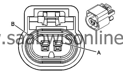
Connector Part Information
|
||||||||||||
Terminal Part Information
|
||||||||||||
R6 Data Link Resistor
| Pin | Wire Color | Circuit No. | Operation |
|
A
|
0.5 YE
|
5169
|
Mid Speed GMLAN Serial Data (+)
|
|
B
|
0.5 WH
|
5170
|
Mid Speed GMLAN Serial Data (-)
|
| S111 Night Panel Switch |
Connector Part Information
|
||||||||||||
Terminal Part Information
|
||||||||||||
S111 Night Panel Switch
| Pin | Wire Color | Circuit No. | Operation |
|
1
|
0.5 BK
|
1650
|
Ground
|
|
2
|
0.5 YE
|
6817
|
LED Backlight Dimming Control
|
|
3
|
0.5 WH/VT
|
6821
|
Surveillance Switch Signal
|
| S25 Garage Door Opener |
Connector Part Information
|
||||||||||||
Terminal Part Information
|
||||||||||||
S25 Garage Door Opener
| Pin | Wire Color | Circuit No. | Operation |
|
1
|
0.5 RD/WH
|
1040
|
Battery Positive Voltage
|
|
2
|
0.5 YE
|
6817
|
LED Backlight Dimming Control
|
|
3
|
0.5 BK
|
1550
|
Ground
|
| S27 Head-Up Display Switch |
Connector Part Information
|
||||||||||||
Terminal Part Information
|
||||||||||||
S27 Head-Up Display Switch
| Pin | Wire Color | Circuit No. | Operation |
|
1
|
0.35 BK/GN
|
5699
|
Low Reference
|
|
2
|
0.5 BK
|
1450
|
Ground
|
|
3
|
0.35 GY/YE
|
5812
|
Head Up Display Dimming Signal
|
|
5
|
0.35 YE
|
6817
|
LED Backlight Dimming Control
|
|
6
|
0.35 YE/WH
|
622
|
Head Up Display Switch Signal
|
| S3 Transmission Shift Lever X1 |
Connector Part Information
|
||||||||||||
Terminal Part Information
|
||||||||||||
S3 Transmission Shift Lever X1
| Pin | Wire Color | Circuit No. | Operation |
|
1
|
0.5 VT
|
801
|
Retained Accessory Power Fuse Supply Voltage
|
|
2
|
0.5 BK
|
1550
|
Ground
|
|
3
|
0.5 VT/YE
|
5526
|
Tap Up/Tap Down Switch Signal
|
|
4
|
0.5 VT/BK
|
7553
|
Park Lock Solenoid Control
|
|
5
|
0.5 YE
|
7554
|
Park Lock Solenoid Soft Control
|
|
6
|
0.5 WH/VT
|
5905
|
Key Capture/Column Lock Shift Position Signal
|
| S3 Transmission Shift Lever X2 |
Connector Part Information
|
||||||||||||
Terminal Part Information
|
||||||||||||
S3 Transmission Shift Lever X2
| Pin | Wire Color | Circuit No. | Operation |
|
1
|
0.5 VT
|
801
|
Retained Accessory Power Fuse Supply Voltage
|
|
2
|
0.5 GN/BU
|
6133
|
Linear Interconnect Network Bus 2
|
|
3
|
0.75 BK
|
1550
|
Ground
|
| S30 Headlamp Switch |
Connector Part Information
|
|||||||||||||||||||||||||||
Terminal Part Information
|
|||||||||||||||||||||||||||
S30 Headlamp Switch
| Pin | Wire Color | Circuit No. | Operation |
|
1
|
0.5 YE
|
7556
|
Lighting Control Switch Reference
|
|
1
|
0.5 YE
|
7556
|
Lighting Control Switch Reference
|
|
2
|
-
|
-
|
Not used
|
|
3
|
0.35 GN/GY
|
13
|
Headlamp Switch Park Lamp Signal
|
|
4
|
0.35 WH/VT
|
103
|
Headlamp Switch On Signal
|
|
5
|
0.35 GN/BN
|
306
|
Headlamp Switch Headlamps Off Signal Control
|
|
6
|
0.5 BK
|
1650
|
Ground
|
|
7
|
0.5 YE
|
6817
|
LED Backlight Dimming Control
|
|
8
|
-
|
-
|
Not used
|
|
9
|
0.5 VT/GN
|
3039
|
Run/Crank Ignition 1 Voltage
|
|
9
|
0.5 VT/GN
|
3039
|
Run/Crank Ignition 1 Voltage
|
|
10
|
0.5 BN/YE
|
189
|
Headlamp Leveling Motor Supply Voltage
|
|
11
|
-
|
-
|
Not used
|
|
12
|
0.5 WH/BN
|
7555
|
Lighting Control Switch Signal
|
| S38 Ignition Mode Switch |
Connector Part Information
|
|||||||||||||||||||||||||||
Terminal Part Information
|
|||||||||||||||||||||||||||
S38 Ignition Mode Switch
| Pin | Wire Color | Circuit No. | Operation |
|
1
|
-
|
-
|
Not used
|
|
2
|
0.35 BN/BK
|
5720
|
Ignition Mode Switch Accessory LED Signal
|
|
3
|
0.5 GN/BK
|
3558
|
Passive Start Switch Signal 2
|
|
4
|
0.5 BK/WH
|
2451
|
Signal Ground
|
|
5
|
0.35 BU/BK
|
5719
|
Ignition Mode Switch Start LED Signal
|
|
6
|
0.5 BU/GN
|
5723
|
Ignition Mode Switch Mode Voltage
|
|
7
|
0.5 BK/GY
|
3559
|
Low Reference
|
|
8
|
0.5 GN/BU
|
5721
|
Ignition Mode Switch Off LED Signal
|
| S40 Passenger Air Bag Disable Switch |
Connector Part Information
|
||||||||||||
Terminal Part Information
|
||||||||||||
S40 Passenger Air Bag Disable Switch
| Pin | Wire Color | Circuit No. | Operation |
|
1
|
0.5 VT/OG
|
371
|
Passenger IP Module Disable Switch Signal
|
|
3
|
0.5 BU/OG
|
7328
|
Passenger IP Module Disable Switch Return
|
| S48B Multi-Function Switch - Overhead Console X1 (C3U) |
Connector Part Information
|
||||||||||||
Terminal Part Information
|
||||||||||||
S48B Multi-Function Switch - Overhead Console X1 (C3U)
| Pin | Wire Color | Circuit No. | Operation |
|
1
|
0.5 BK/GY
|
128
|
Low Reference
|
|
2
|
0.5 YE
|
6817
|
LED Backlight Dimming Control
|
|
3
|
0.5 BK
|
1550
|
Ground
|
|
4
|
0.5 BU/VT
|
5027
|
Sunroof Switch Data (1)
|
| S48B Multi-Function Switch - Overhead Console X3 (C3U) |
Connector Part Information
|
||||||||||||
Terminal Part Information
|
||||||||||||
S48B Multi-Function Switch - Overhead Console X3 (C3U)
| Pin | Wire Color | Circuit No. | Operation |
|
1
|
0.5 BK/BU
|
5307
|
Low Reference
|
|
2
|
0.5 YE
|
6817
|
LED Backlight Dimming Control
|
|
3
|
0.5 BK
|
1550
|
Ground
|
|
4
|
0.5 BU/GY
|
3032
|
Front Sunshade Switch Signal
|
| S48B Multi-Function Switch - Overhead Console X4 (UE1) |
Connector Part Information
|
||||||||||||
Terminal Part Information
|
||||||||||||
S48B Multi-Function Switch - Overhead Console X4 (UE1)
| Pin | Wire Color | Circuit No. | Operation |
|
A
|
0.5 BARE
|
654
|
Low Reference
|
|
B
|
0.5 BU
|
655
|
Cellular Telephone Microphone Signal
|
| S48B Multi-Function Switch - Overhead Console X5 (UXG/UXY/UYS/UYT/UYU/UYV/UYW/UYX/U44) |
Connector Part Information
|
||||||||||||
Terminal Part Information
|
||||||||||||
S48B Multi-Function Switch - Overhead Console X5 (UXG/UXY/UYS/UYT/UYU/UYV/UYW/UYX/U44)
| Pin | Wire Color | Circuit No. | Operation |
|
2
|
0.5 BK/BN
|
654
|
Low Reference
|
|
2
|
0.5 BARE
|
654
|
Low Reference
|
|
3
|
0.5 BU
|
655
|
Cellular Telephone Microphone Signal
|
|
3
|
0.5 BU
|
655
|
Cellular Telephone Microphone Signal
|
| S48B Multi-Function Switch - Overhead Console X6 (UTV) |
Connector Part Information
|
||||||||||||
Terminal Part Information
|
||||||||||||
S48B Multi-Function Switch - Overhead Console X6 (UTV)
| Pin | Wire Color | Circuit No. | Operation |
|
1
|
0.5 VT/BK
|
5068
|
Intrusion Sensor Switch Disable Signal
|
|
2
|
0.5 VT/GY
|
5059
|
Intrusion Sensor Alarm On Signal
|
|
3
|
0.5 YE
|
5058
|
Intrusion Sensor Armed Signal
|
|
4
|
0.5 GN/BN
|
6132
|
Linear Interconnect Network Bus 1
|
|
5
|
0.5 BK
|
1550
|
Ground
|
| S48B Multi-Function Switch - Overhead Console X7 (UTV) |
Connector Part Information
|
||||||||||||
Terminal Part Information
|
||||||||||||
S48B Multi-Function Switch - Overhead Console X7 (UTV)
| Pin | Wire Color | Circuit No. | Operation |
|
1
|
0.5 VT/BK
|
5068
|
Intrusion Sensor Switch Disable Signal
|
|
2
|
0.5 BK
|
1550
|
Ground
|
|
3
|
0.5 YE
|
6817
|
LED Backlight Dimming Control
|
|
4
|
0.5 VT/GY
|
5059
|
Intrusion Sensor Alarm On Signal
|
| S48B Multi-Function Switch - Overhead Console X8 |
Connector Part Information
|
||||||||||||
Terminal Part Information
|
||||||||||||
S48B Multi-Function Switch - Overhead Console X8
| Pin | Wire Color | Circuit No. | Operation |
|
1
|
0.5 WH/BN
|
6815
|
Inadvertent Power Control
|
|
2
|
0.5 GY
|
157
|
Interior Lamp Control
|
|
3
|
0.5 YE
|
6817
|
LED Backlight Dimming Control
|
|
4
|
0.5 GY/GN
|
328
|
Interior Lamp Defeat Switch Signal
|
|
5
|
0.5 GY
|
156
|
Courtesy Lamp Switch Signal
|
|
6
|
0.5 BK
|
1550
|
Ground
|
| S48B Multi-Function Switch - Overhead Console X9 |
Connector Part Information
|
||||||||||||
Terminal Part Information
|
||||||||||||
S48B Multi-Function Switch - Overhead Console X9
| Pin | Wire Color | Circuit No. | Operation |
|
1
|
0.35 BU
|
2307
|
Passenger Air Bag ON Indicator Control
|
|
2
|
0.35 BK/WH
|
2151
|
Signal Ground
|
|
3
|
0.35 GN
|
2308
|
Passenger Air Bag Off Indicator Control
|
|
4
|
0.35 VT/GY
|
3139
|
Run/Crank Ignition 1 Voltage
|
|
5
|
0.35 VT/WH
|
5234
|
Passenger Seat Belt Indicator
|
| S48C Multi-Function Switch 1 - Instrument Panel (URC) |
Connector Part Information
|
||||||||||||
Terminal Part Information
|
||||||||||||
S48C Multi-Function Switch 1 - Instrument Panel (URC)
| Pin | Wire Color | Circuit No. | Operation |
|
1
|
0.5 WH
|
6816
|
Indicator Dimming Control
|
|
1
|
0.5 WH
|
6816
|
Indicator Dimming Control
|
|
2
|
0.5 YE
|
9382
|
Transmission Sport Mode Indicator Control
|
|
3
|
0.5 BU/GY
|
553
|
Shift Select Switch Performance Signal
|
|
4
|
0.5 GY
|
5054
|
Sport Mode Switch Signal
|
|
5
|
0.5 BK
|
1850
|
Ground
|
|
6
|
0.5 YE
|
9381
|
Transmission Intelligent Mode Indicator Control
|
|
7
|
0.5 YE
|
9383
|
Transmission Comfort Mode Indicator Control
|
|
9
|
0.5 BU/VT
|
1788
|
Traction Control Switch Signal (1)
|
|
10
|
0.5 YE
|
6817
|
LED Backlight Dimming Control
|
| S48C Multi-Function Switch 1 - Instrument Panel (without URC) |
Connector Part Information
|
||||||||||||
Terminal Part Information
|
||||||||||||
S48C Multi-Function Switch 1 - Instrument Panel (without URC)
| Pin | Wire Color | Circuit No. | Operation |
|
1
|
0.5 BK
|
1850
|
Ground
|
|
2
|
0.5 YE
|
6817
|
LED Backlight Dimming Control
|
|
3
|
0.5 BU/VT
|
1788
|
Traction Control Switch Signal (1)
|
| S48D Multifunction Switch 2 - Instrument Panel |
Connector Part Information
|
||||||||||||
Terminal Part Information
|
||||||||||||
S48D Multifunction Switch 2 - Instrument Panel
| Pin | Wire Color | Circuit No. | Operation |
|
1
|
0.5 BK
|
1650
|
Ground
|
|
2
|
0.5 GY
|
5697
|
Child Lockout Indicator
|
|
3
|
0.5 WH
|
6816
|
Indicator Dimming Control
|
|
4
|
0.35 GN/WH
|
111
|
Hazard Switch Signal
|
|
5
|
0.35 GY/YE
|
7543
|
Hazard LED Dimming Signal
|
|
6
|
0.5 YE/BN
|
3265
|
Child Security Lock Switch Signal
|
|
7
|
0.5 BN/YE
|
780
|
Driver Door Lock Switch Lock Signal
|
|
9
|
0.5 BN/WH
|
781
|
Driver Door Lock Switch Unlock Signal
|
|
10
|
0.5 YE
|
6817
|
LED Backlight Dimming Control
|
| S48E Multi-Function Switch Module - Center Console |
Connector Part Information
|
||||||||||||
Terminal Part Information
|
||||||||||||
S48E Multi-Function Switch Module - Center Console
| Pin | Wire Color | Circuit No. | Operation |
|
1
|
0.5 YE
|
6817
|
LED Backlight Dimming Control
|
|
2
|
0.5 BK
|
1850
|
Ground
|
|
3
|
0.5 WH
|
6816
|
Indicator Dimming Control
|
|
3
|
0.5 WH
|
6816
|
Indicator Dimming Control
|
|
4
|
0.5 BU/BN
|
3161
|
Parallel Park Assist Disable Switch Signal
|
|
5
|
0.5 GY/GN
|
2555
|
Rear Park Assist Disable Signal
|
|
6
|
0.5 GN/BN
|
5852
|
Rear Park Assist LED Disable Signal
|
|
7
|
0.5 GY/WH
|
3153
|
Lane Departure Warning Disable Switch Signal
|
|
8
|
0.5 WH
|
3152
|
Lane Departure Warning Indicator Control
|
| S52 Outside Rearview Mirror Switch (LHD) |
Connector Part Information
|
||||||||||||
Terminal Part Information
|
||||||||||||
S52 Outside Rearview Mirror Switch (LHD)
| Pin | Wire Color | Circuit No. | Operation |
|
1
|
0.5 VT/BU
|
3390
|
Driver Mirror Motor Up (+) Down (-) Control
|
|
1
|
0.5 VT/BU
|
3390
|
Driver Mirror Motor Up (+) Down (-) Control
|
|
2
|
0.5 YE/BN
|
3391
|
Driver Mirror Motor Common Control
|
|
2
|
0.5 YE/BN
|
3391
|
Driver Mirror Motor Common Control
|
|
3
|
0.5 BN/BK
|
3389
|
Driver Mirror Motor Right (+) Left (-) Control
|
|
3
|
0.5 BN/BK
|
3389
|
Driver Mirror Motor Right (+) Left (-) Control
|
|
4
|
0.5 RD/GY
|
2840
|
Battery Positive Voltage
|
|
4
|
0.5 RD/GY
|
2840
|
Battery Positive Voltage
|
|
5
|
0.5 BK
|
1550
|
Ground
|
|
5
|
0.5 BK
|
1550
|
Ground
|
|
6
|
0.5 GN/WH
|
7530
|
Linear Interconnect Network Bus 8
|
|
7
|
0.5 YE/VT
|
3397
|
Co-Driver Mirror Motor Up (+) Down (-) Control
|
|
7
|
0.5 BK/BN
|
3393
|
Low Reference
|
|
8
|
0.5 WH
|
3398
|
Co-Driver Mirror Motor Common Control
|
|
8
|
0.5 GY/BN
|
3394
|
Driver Mirror Position Sensor Up (+) Down (-) Signal
|
|
9
|
0.5 GN/BK
|
3396
|
Co-Driver Mirror Motor Right (+) Left (-) Control
|
|
9
|
0.5 WH/YE
|
3395
|
Driver Mirror Position Sensor Left (-) Right (+) Signal
|
|
10
|
0.5 YE
|
6817
|
LED Backlight Dimming Control
|
|
10
|
0.5 VT/RD
|
3392
|
Driver Mirror Position Sensor High Reference
|
|
11
|
0.5 GY/WH
|
3411
|
Driver Mirror Motor Fold Out Control
|
|
11
|
0.5 VT/YE
|
3409
|
Mirror Motor Fold Out Control
|
|
12
|
0.5 WH/GN
|
3412
|
Driver Mirror Motor Fold In Control
|
|
12
|
0.5 WH/BN
|
3410
|
Mirror Motor Fold In Control
|
| S52 Outside Rearview Mirror Switch (RHD) |
Connector Part Information
|
||||||||||||
Terminal Part Information
|
||||||||||||
S52 Outside Rearview Mirror Switch (RHD)
| Pin | Wire Color | Circuit No. | Operation |
|
1
|
0.5 YE/VT
|
3397
|
Co-Driver Mirror Motor Up (+) Down (-) Control
|
|
1
|
0.5 VT/BU
|
3390
|
Driver Mirror Motor Up (+) Down (-) Control
|
|
2
|
0.5 WH
|
3398
|
Co-Driver Mirror Motor Common Control
|
|
2
|
0.5 YE/BN
|
3391
|
Driver Mirror Motor Common Control
|
|
3
|
0.5 BN/BK
|
3389
|
Driver Mirror Motor Right (+) Left (-) Control
|
|
3
|
0.5 GN/BK
|
3396
|
Co-Driver Mirror Motor Right (+) Left (-) Control
|
|
4
|
0.5 RD/GY
|
2840
|
Battery Positive Voltage
|
|
4
|
0.5 RD/GY
|
2840
|
Battery Positive Voltage
|
|
5
|
0.5 BK
|
2050
|
Ground
|
|
5
|
0.5 BK
|
1550
|
Ground
|
|
6
|
0.5 GN/WH
|
7530
|
Linear Interconnect Network Bus 8
|
|
7
|
0.5 BK/BN
|
3393
|
Low Reference
|
|
7
|
0.5 VT/BU
|
3390
|
Driver Mirror Motor Up (+) Down (-) Control
|
|
8
|
0.5 YE/BN
|
3391
|
Driver Mirror Motor Common Control
|
|
8
|
0.5 GY/BN
|
3394
|
Driver Mirror Position Sensor Up (+) Down (-) Signal
|
|
9
|
0.5 BN/BK
|
3389
|
Driver Mirror Motor Right (+) Left (-) Control
|
|
9
|
0.5 WH/YE
|
3395
|
Driver Mirror Position Sensor Left (-) Right (+) Signal
|
|
10
|
0.5 YE
|
6817
|
LED Backlight Dimming Control
|
|
10
|
0.5 VT/RD
|
3392
|
Driver Mirror Position Sensor High Reference
|
|
11
|
0.5 GY/WH
|
3411
|
Driver Mirror Motor Fold Out Control
|
|
11
|
0.5 VT/YE
|
3409
|
Mirror Motor Fold Out Control
|
|
12
|
0.5 WH/GN
|
3412
|
Driver Mirror Motor Fold In Control
|
|
12
|
0.5 WH/BN
|
3410
|
Mirror Motor Fold In Control
|
| S78 Turn Signal/Multi-Function Switch |
Connector Part Information
|
||||||||||||
Terminal Part Information
|
||||||||||||
S78 Turn Signal/Multi-Function Switch
| Pin | Wire Color | Circuit No. | Operation |
|
1
|
0.5 WH/GN
|
663
|
Hazard Switch Left Turn Signal
|
|
2
|
0.5 WH
|
524
|
Headlamp Dimmer Switch High Beam Signal
|
|
3
|
0.5 BK
|
1850
|
Ground
|
|
4
|
0.5 YE/BN
|
307
|
Headlamp Switch Flash To Pass Signal
|
|
5
|
0.35 GY/BU
|
893
|
Driver Information Center Select Menu Switch Signal
|
|
6
|
0.35 BK/BN
|
897
|
Low Reference
|
|
7
|
0.5 VT/BU
|
664
|
Hazard Switch Right Turn Signal
|
|
12
|
0.35 GN/WH
|
1358
|
Driver Information Center Switch Signal
|
| S79D Window Switch - Driver (LHD) |
Connector Part Information
|
||||||||||||
Terminal Part Information
|
||||||||||||
S79D Window Switch - Driver (LHD)
| Pin | Wire Color | Circuit No. | Operation |
|
1
|
0.5 BK
|
1550
|
Ground
|
|
2
|
0.5 GN
|
3381
|
Power Window Switch Driver Express Signal
|
|
3
|
0.5 GY
|
3380
|
Power Window Switch Driver Down Signal
|
|
4
|
0.5 RD/GY
|
2840
|
Battery Positive Voltage
|
|
5
|
0.5 GN/YE
|
6134
|
Linear Interconnect Network Bus 3
|
|
6
|
0.5 GN/WH
|
3379
|
Power Window Switch Driver Up Signal
|
|
7
|
0.5 WH/VT
|
3270
|
Driver Door Lock Motor Status Control
|
|
8
|
0.5 BU/VT
|
1124
|
Door Lock Key Switch Unlock Signal
|
| S79D Window Switch - Driver (RHD) |
Connector Part Information
|
||||||||||||
Terminal Part Information
|
||||||||||||
S79D Window Switch - Driver (RHD)
| Pin | Wire Color | Circuit No. | Operation |
|
1
|
0.5 BK
|
2050
|
Ground
|
|
2
|
0.5 GN
|
3381
|
Power Window Switch Driver Express Signal
|
|
3
|
0.5 GY
|
3380
|
Power Window Switch Driver Down Signal
|
|
4
|
0.5 RD/GY
|
2840
|
Battery Positive Voltage
|
|
5
|
0.5 GN/YE
|
6134
|
Linear Interconnect Network Bus 3
|
|
6
|
0.5 GN/WH
|
3379
|
Power Window Switch Driver Up Signal
|
|
7
|
0.5 WH/VT
|
3270
|
Driver Door Lock Motor Status Control
|
|
8
|
0.5 BU/VT
|
1124
|
Door Lock Key Switch Unlock Signal
|
| S79LR Window Switch - Left Rear (AEQ) |
Connector Part Information
|
||||||||||||||||||||||||
Terminal Part Information
|
||||||||||||||||||||||||
S79LR Window Switch - Left Rear (AEQ)
| Pin | Wire Color | Circuit No. | Operation |
|
1
|
0.5 GN/GY
|
6135
|
Linear Interconnect Network Bus 4
|
|
2
|
0.5 GY
|
747
|
Left Rear Door Ajar Switch Signal
|
|
3
|
0.5 BK
|
2350
|
Ground
|
|
5
|
2.5 BK
|
2350
|
Ground
|
|
6
|
2.5 BU/VT
|
668
|
Power Window Motor Left Rear Up Control
|
|
7
|
2.5 YE/BU
|
669
|
Power Window Motor Left Rear Down Control
|
|
8
|
2.5 RD/BN
|
2940
|
Battery Positive Voltage
|
| S79LR Window Switch - Left Rear (AER) |
Connector Part Information
|
|||||||||||||||
Terminal Part Information
|
|||||||||||||||
S79LR Window Switch - Left Rear (AER)
| Pin | Wire Color | Circuit No. | Operation |
|
1
|
0.5 BK
|
2350
|
Ground
|
|
4
|
0.35 YE
|
6817
|
LED Backlight Dimming Control
|
|
6
|
0.5 GN/GY
|
1185
|
Power Window Switch Left Rear Up Signal
|
|
7
|
0.5 BN/BU
|
1187
|
Power Window Switch Left Rear Down Signal
|
|
8
|
0.5 GY/GN
|
5048
|
Power Window Switch Left Rear Express Signal
|
| S79P Window Switch - Passenger (LHD) |
Connector Part Information
|
||||||||||||
Terminal Part Information
|
||||||||||||
S79P Window Switch - Passenger (LHD)
| Pin | Wire Color | Circuit No. | Operation |
|
1
|
0.5 BK
|
2050
|
Ground
|
|
1
|
0.5 YE/WH
|
3413
|
Co-Driver Mirror Motor Fold Out Control
|
|
2
|
0.5 YE
|
6817
|
LED Backlight Dimming Control
|
|
2
|
0.5 YE/VT
|
3397
|
Co-Driver Mirror Motor Up (+) Down (-) Control
|
|
3
|
0.5 WH
|
3398
|
Co-Driver Mirror Motor Common Control
|
|
4
|
0.5 YE/RD
|
3399
|
Co-Driver Mirror Position Sensor High Reference
|
|
5
|
0.5 BU/YE
|
3401
|
Co-Driver Mirror Position Sensor Up (+) Down (-) Signal
|
|
6
|
0.5 BK/GN
|
3400
|
Low Reference
|
|
6
|
0.5 VT/GY
|
3386
|
Power Window Switch Co-Driver Express Signal
|
|
7
|
0.5 BU/GY
|
3414
|
Co-Driver Mirror Motor Fold In Control
|
|
7
|
0.5 BN/YE
|
3385
|
Power Window Switch Driver Down Signal
|
|
8
|
0.5 YE/BK
|
3384
|
Power Window Switch Co-Driver Up Signal
|
|
8
|
0.5 GN/BK
|
3396
|
Co-Driver Mirror Motor Right (+) Left (-) Control
|
|
9
|
0.5 GN/WH
|
7530
|
Linear Interconnect Network Bus 8
|
|
11
|
0.5 VT/WH
|
3403
|
Co-Driver Mirror Position Sensor Left (-) Right (+) Signal
|
| S79P Window Switch - Passenger X1 (LHD) |
Connector Part Information
|
||||||||||||
Terminal Part Information
|
||||||||||||
S79P Window Switch - Passenger X1 (LHD)
| Pin | Wire Color | Circuit No. | Operation |
|
1
|
0.5 BK
|
2050
|
Ground
|
|
2
|
0.5 YE
|
6817
|
LED Backlight Dimming Control
|
|
4
|
0.5 RD/GY
|
2840
|
Battery Positive Voltage
|
|
6
|
0.5 VT/GY
|
3386
|
Power Window Switch Co-Driver Express Signal
|
|
7
|
0.5 BN/YE
|
3385
|
Power Window Switch Driver Down Signal
|
|
8
|
0.5 YE/BK
|
3384
|
Power Window Switch Co-Driver Up Signal
|
| S79P Window Switch - Passenger X1 (RHD) |
Connector Part Information
|
||||||||||||
Terminal Part Information
|
||||||||||||
S79P Window Switch - Passenger X1 (RHD)
| Pin | Wire Color | Circuit No. | Operation |
|
1
|
0.5 BK
|
1550
|
Ground
|
|
2
|
0.5 YE
|
6817
|
LED Backlight Dimming Control
|
|
4
|
0.5 RD/GY
|
2840
|
Battery Positive Voltage
|
|
6
|
0.5 VT/GY
|
3386
|
Power Window Switch Co-Driver Express Signal
|
|
7
|
0.5 BN/YE
|
3385
|
Power Window Switch Driver Down Signal
|
|
8
|
0.5 YE/BK
|
3384
|
Power Window Switch Co-Driver Up Signal
|
| S79P Window Switch - Passenger X2 (RHD) |
Connector Part Information
|
||||||||||||
Terminal Part Information
|
||||||||||||
S79P Window Switch - Passenger X2 (RHD)
| Pin | Wire Color | Circuit No. | Operation |
|
1
|
0.5 BK
|
1550
|
Ground
|
|
1
|
0.5 YE/WH
|
3413
|
Co-Driver Mirror Motor Fold Out Control
|
|
2
|
0.5 YE
|
6817
|
LED Backlight Dimming Control
|
|
2
|
0.5 YE/VT
|
3397
|
Co-Driver Mirror Motor Up (+) Down (-) Control
|
|
3
|
0.5 WH
|
3398
|
Co-Driver Mirror Motor Common Control
|
|
4
|
0.5 YE/RD
|
3399
|
Co-Driver Mirror Position Sensor High Reference
|
|
5
|
0.5 BU/YE
|
3401
|
Co-Driver Mirror Position Sensor Up (+) Down (-) Signal
|
|
6
|
0.5 BK/GN
|
3400
|
Low Reference
|
|
6
|
0.5 VT/GY
|
3386
|
Power Window Switch Co-Driver Express Signal
|
|
7
|
0.5 BU/GY
|
3414
|
Co-Driver Mirror Motor Fold In Control
|
|
7
|
0.5 BN/YE
|
3385
|
Power Window Switch Driver Down Signal
|
|
8
|
0.5 YE/BK
|
3384
|
Power Window Switch Co-Driver Up Signal
|
|
8
|
0.5 GN/BK
|
3396
|
Co-Driver Mirror Motor Right (+) Left (-) Control
|
|
9
|
0.5 GN/WH
|
7530
|
Linear Interconnect Network Bus 8
|
|
11
|
0.5 VT/WH
|
3403
|
Co-Driver Mirror Position Sensor Left (-) Right (+) Signal
|
| S79RR Window Switch - Right Rear (AEQ) |
Connector Part Information
|
||||||||||||||||||||||||
Terminal Part Information
|
||||||||||||||||||||||||
S79RR Window Switch - Right Rear (AEQ)
| Pin | Wire Color | Circuit No. | Operation |
|
1
|
0.5 GN/GY
|
6135
|
Linear Interconnect Network Bus 4
|
|
2
|
0.5 GY
|
748
|
Right Rear Door Ajar Switch Signal
|
|
5
|
2.5 BK
|
2050
|
Ground
|
|
6
|
2.5 BU/GY
|
670
|
Power Window Motor Right Rear Up Control
|
|
7
|
2.5 GN/BK
|
671
|
Power Window Motor Right Rear Down Control
|
|
8
|
2.5 RD/BN
|
2940
|
Battery Positive Voltage
|
| S79RR Window Switch - Right Rear (AER) |
Connector Part Information
|
|||||||||||||||
Terminal Part Information
|
|||||||||||||||
S79RR Window Switch - Right Rear (AER)
| Pin | Wire Color | Circuit No. | Operation |
|
1
|
0.5 BK
|
2350
|
Ground
|
|
4
|
0.35 YE
|
6817
|
LED Backlight Dimming Control
|
|
6
|
0.5 GN/GY
|
1186
|
Power Window Switch Right Rear Up Signal
|
|
7
|
0.5 BN/BU
|
1188
|
Power Window Switch Right Rear Down Signal
|
|
8
|
0.5 WH/GN
|
5049
|
Power Window Switch Right Rear Express Signal
|
| S82 Windshield Wiper/Washer Switch |
Connector Part Information
|
||||||||||||
Terminal Part Information
|
||||||||||||
S82 Windshield Wiper/Washer Switch
| Pin | Wire Color | Circuit No. | Operation |
|
1
|
0.5 GY
|
1715
|
Windshield Wiper Switch High Signal
|
|
2
|
0.5 BK/GY
|
6009
|
Low Reference
|
|
3
|
0.5 YE/BU
|
1714
|
Windshield Wiper Switch Low Signal
|
|
5
|
0.5 WH/BK
|
94
|
Windshield Washer Switch Signal
|
| T8A Ignition Coil 1 (LAU or LDK) |
Connector Part Information
|
||||||||||||
Terminal Part Information
|
||||||||||||
T8A Ignition Coil 1 (LAU or LDK)
| Pin | Wire | Circuit | Operation |
|
A
|
0.5 BK
|
250
|
Ground
|
|
B
|
0.5 BK/BU
|
2129
|
Ignition Control Low Reference Bank 1
|
|
C
|
0.5 BU/VT
|
2121
|
Ignition Control (1)
|
|
D
|
0.5 RD/BU
|
5291
|
Powertrain Main Relay Fused Supply (2) (LDK)
|
|
1.0 RD/BU
|
5290
|
Powertrain Main Relay Fused Supply (1) (LAU)
|
| T8B Ignition Coil 2 (LAU or LDK) |
Connector Part Information
|
||||||||||||
Terminal Part Information
|
||||||||||||
T8B Ignition Coil 2 (LAU or LDK)
| Pin | Wire | Circuit | Operation |
|
A
|
0.5 BK
|
250
|
Ground
|
|
B
|
0.5 BK/BU
|
2129
|
Ignition Control Low Reference Bank 1 (LAU)
|
|
0.5 BK/GY
|
2130
|
Ignition Control Low Reference Bank 2 (LDK)
|
|
|
C
|
0.5 BU/WH
|
2122
|
Ignition Control (2) (LAU)
|
|
0.5 BU/BN
|
2122
|
Ignition Control (2) (LDK)
|
|
|
D
|
0.5 RD/BU
|
5291
|
Powertrain Main Relay Fused Supply (2) (LDK)
|
|
1.0 RD/BU
|
5290
|
Powertrain Main Relay Fused Supply (1) (LAU)
|
| T8C Ignition Coil 3 (LAU or LDK) |
Connector Part Information
|
||||||||||||
Terminal Part Information
|
||||||||||||
T8C Ignition Coil 3 (LAU or LDK)
| Pin | Wire | Circuit | Operation |
|
A
|
0.5 BK
|
250
|
Ground
|
|
B
|
0.5 BK/BU
|
2129
|
Ignition Control Low Reference Bank 1
|
|
C
|
0.5 GN/BU
|
2123
|
Ignition Control (3)
|
|
D
|
0.5 RD/BU
|
5291
|
Powertrain Main Relay Fused Supply (2) (LDK)
|
|
1.0 RD/BU
|
5290
|
Powertrain Main Relay Fused Supply (1) (LAU)
|
| T8D Ignition Coil 4 (LAU or LDK) |
Connector Part Information
|
||||||||||||
Terminal Part Information
|
||||||||||||
T8B Ignition Coil 2 (LAU or LDK)
| Pin | Wire | Circuit | Operation |
|
A
|
0.5 BK
|
250
|
Ground
|
|
B
|
0.5 BK/BU
|
2129
|
Ignition Control Low Reference Bank 1 (LAU)
|
|
0.5 BK/GY
|
2130
|
Ignition Control Low Reference Bank 2 (LDK)
|
|
|
C
|
0.5 YE/BU
|
2124
|
Ignition Control (4) (LAU)
|
|
0.5 YE/WH
|
2124
|
Ignition Control (4) (LDK)
|
|
|
D
|
0.5 RD/BU
|
5291
|
Powertrain Main Relay Fused Supply (2) (LDK)
|
|
1.0 RD/BU
|
5290
|
Powertrain Main Relay Fused Supply (1) (LAU)
|
| T8E Ignition Coil 5 (LAU) |
Connector Part Information
|
||||||||||||
Terminal Part Information
|
||||||||||||
T8E Ignition Coil 5 (LAU)
| Pin | Wire | Circuit | Operation |
|
A
|
0.5 BK
|
250
|
Ground
|
|
B
|
0.5 BK/BU
|
2129
|
Ignition Control Low Reference Bank 1
|
|
C
|
0.5 BU/VT
|
2125
|
Ignition Control (5)
|
|
D
|
1.0 RD/BU
|
5290
|
Powertrain Main Relay Fused Supply (1)
|
| T8F Ignition Coil 6 (LAU) |
Connector Part Information
|
||||||||||||
Terminal Part Information
|
||||||||||||
T8F Ignition Coil 6 (LAU)
| Pin | Wire | Circuit | Operation |
|
A
|
0.5 BK
|
250
|
Ground
|
|
B
|
0.5 BK/BU
|
2129
|
Ignition Control Low Reference Bank 1
|
|
C
|
0.5 BN/BU
|
2126
|
Ignition Control (6)
|
|
D
|
1.0 RD/BU
|
5290
|
Powertrain Main Relay Fused Supply (1)
|
| T10E Keyless Entry Antenna - Rear Compartment |
Connector Part Information
|
||||||||||||
Terminal Part Information
|
||||||||||||
T10E Keyless Entry Antenna - Rear Compartment
| Pin | Wire Color | Circuit No. | Operation |
|
1
|
0.5 WH/GN
|
3556
|
Passive Start Interior Antenna 3 Signal Hi
|
|
2
|
0.5 GN
|
3557
|
Passive Start Interior Antenna 3 Signal Lo
|
| T10F Keyless Entry Antenna - Rear Window |
Connector Part Information
|
||||||||||||
Terminal Part Information
|
||||||||||||
T10F Keyless Entry Antenna - Rear Window
| Pin | Wire Color | Circuit No. | Operation |
|
1
|
0.5 BU
|
3554
|
Passive Start Interior Antenna 2 Signal Hi
|
|
2
|
0.5 GY/BK
|
3555
|
Passive Start Interior Antenna 2 Signal Lo
|
| T10G Keyless Entry Antenna - Rear Fascia |
Connector Part Information
|
||||||||||||
Terminal Part Information
|
||||||||||||
T10G Keyless Entry Antenna - Rear Fascia
| Pin | Wire Color | Circuit No. | Operation |
|
1
|
0.5 BN/GN
|
3568
|
Passive Entry Rear Closure Antenna Signal Hi
|
|
2
|
0.5 GN/GY
|
3569
|
Passive Entry Rear Closure Antenna Signal Lo
|
| T10J Keyless Entry Antenna - Center Console Front |
Connector Part Information
|
||||||||||||
Terminal Part Information
|
||||||||||||
T10J Keyless Entry Antenna - Center Console Front
| Pin | Wire Color | Circuit No. | Operation |
|
1
|
0.5 BN/BK
|
3552
|
Passive Start Interior Antenna 1 Signal Hi
|
|
2
|
0.5 WH
|
3553
|
Passive Start Interior Antenna 1 Signal Lo
|
| T11 Multimedia Player Interface Module |
Connector Part Information
|
||||||||||||
Terminal Part Information
|
||||||||||||
T11 Multimedia Player Interface Module
| Pin | Wire Color | Circuit No. | Operation |
|
1
|
0.5 RD/GN
|
3140
|
Battery Positive Voltage
|
|
2
|
0.35 BU
|
2060
|
Auxiliary Detection Signal
|
|
3
|
0.35 BN
|
3374
|
Auxiliary Audio Common Signal (2)
|
|
4
|
0.35 GN
|
3376
|
Auxiliary Audio Common Signal (3)
|
|
5
|
0.35 BARE
|
3375
|
Auxiliary Audio Drain Wire (3)
|
|
6-7
|
-
|
-
|
Not used
|
|
8
|
0.5 GN
|
5060
|
Low Speed GMLAN Serial Data
|
|
9
|
0.35 WH
|
5170
|
Mid Speed GMLAN Serial Data (-)
|
|
9
|
0.35 WH
|
5170
|
Mid Speed GMLAN Serial Data (-)
|
|
10
|
-
|
-
|
Not used
|
|
11
|
0.5 BK
|
1750
|
Ground
|
|
12
|
0.35 GY
|
5839
|
Left Auxiliary Audio Signal (2)
|
|
13
|
0.35 GN
|
5841
|
Right Auxiliary Audio Signal (2)
|
|
14
|
0.35 VT
|
3377
|
Left Auxiliary Audio Signal (3)
|
|
15
|
0.35 BN
|
3378
|
Right Auxiliary Audio Signal (3)
|
|
16-17
|
-
|
-
|
Not used
|
|
18
|
0.35 BARE
|
5842
|
Auxiliary Audio Screen (2)
|
|
19
|
0.35 YE
|
5169
|
Mid Speed GMLAN Serial Data (+)
|
|
19
|
0.35 YE
|
5169
|
Mid Speed GMLAN Serial Data (+)
|
|
20
|
-
|
-
|
Not used
|
| T3 Audio Amplifier X1 (UQS) |
Connector Part Information
|
||||||||||||||||||||||||
Terminal Part Information
|
||||||||||||||||||||||||
T3 Audio Amplifier X1 (UQS)
| Pin | Wire Color | Circuit No. | Operation |
|
2
|
1 BU/GY
|
346
|
Left/Rear Subwoofer Speaker (+)
|
|
3
|
1 GN/VT
|
1795
|
Right Subwoofer Speaker (+)
|
|
4
|
2.5 RD/GY
|
1042
|
Battery Positive Voltage
|
|
6
|
1 GN/BK
|
1794
|
Left/Rear Subwoofer Speaker (-)
|
|
7
|
1 GY/BK
|
315
|
Right Subwoofer Speaker (-)
|
|
8
|
2.5 BK
|
450
|
Ground
|
| T3 Audio Amplifier X2 (UQS) |
Connector Part Information
|
||||||||||||
Terminal Part Information
|
||||||||||||
T3 Audio Amplifier X2 (UQS)
| Pin | Wire Color | Circuit No. | Operation |
|
2
|
1 BN/BU
|
118
|
Left Front Speaker Signal (-) (1)
|
|
3
|
1 YE/BK
|
117
|
Right Front Speaker Signal (-) (1)
|
|
4
|
1 GN
|
199
|
Left Rear Speaker (+)
|
|
5
|
1 WH
|
46
|
Right Rear Speaker (+)
|
|
6
|
1 BU/YE
|
1960
|
Front Center Speaker (-)
|
|
7
|
1 VT/BK
|
5771
|
Left Rear Shelf Speaker (-)
|
|
10
|
1 BU
|
201
|
Left Front Speaker (+) (1)
|
|
11
|
1 YE
|
200
|
Right Front Speaker (+) (1)
|
|
12
|
1 GN/BK
|
116
|
Left Rear Speaker Signal (-)
|
|
13
|
1 BU/BK
|
115
|
Right Rear Speaker Signal (-)
|
|
14
|
1 YE/WH
|
1860
|
Front Center Speaker (+)
|
|
15
|
1 BU/BN
|
5761
|
Left Rear Shelf Speaker (+)
|
| T3 Audio Amplifier X3 (UQS) |
Connector Part Information
|
||||||||||||
Terminal Part Information
|
||||||||||||
T3 Audio Amplifier X3 (UQS)
| Pin | Wire Color | Circuit No. | Operation |
|
1
|
0.5 BN/BU
|
1947
|
Left Front Low Level Audio (-)
|
|
2
|
0.5 BU/BN
|
1546
|
Front Low Level Audio (-)
|
|
3
|
0.5 BN/VT
|
1999
|
Left Rear Low Level Audio (-)
|
|
4
|
0.5 BU/BK
|
1946
|
Right Rear Low Level Audio (-)
|
|
6
|
0.5 VT/BU
|
6978
|
Amplifier Control
|
|
7
|
0.5 VT/BU
|
6760
|
Center Channel Low Level Audio Signal
|
|
8
|
0.5 BU/VT
|
6763
|
Subwoofer Low Level Audio Signal
|
|
9
|
0.5 BU
|
511
|
Left Front Low Level Audio Signal
|
|
10
|
0.5 YE
|
512
|
Right Front Low Level Audio Signal
|
|
11
|
0.5 GN/BK
|
599
|
Left Rear Low Level Audio Signal
|
|
12
|
0.5 BN/WH
|
546
|
Right Rear Low Level Audio Signal
|
|
13
|
0.35 GN/YE
|
7066
|
Entertainment Remote Enable Signal
|
|
15
|
0.5 GN/BU
|
6761
|
Center Channel Low Level Audio Signal
|
|
16
|
0.5 WH/BK
|
6762
|
Subwoofer Low Level Audio (-)
|
| X80C Accessory Power Receptacle - Cargo (KC8) |
Connector Part Information
|
||||||||||||
Terminal Part Information
|
||||||||||||
X80C Accessory Power Receptacle - Cargo (KC8)
| Pin | Wire Color | Circuit No. | Operation |
|
A
|
2.5 VT
|
801
|
Retained Accessory Power Fuse Supply Voltage
|
|
C
|
2.5 BK
|
3450
|
Ground
|
| X80H Accessory Power Receptacle - Center Console |
Connector Part Information
|
||||||||||||
Terminal Part Information
|
||||||||||||
X80H Accessory Power Receptacle - Center Console
| Pin | Wire Color | Circuit No. | Operation |
|
A
|
2.5 VT
|
801
|
Retained Accessory Power Fuse Supply Voltage
|
|
C
|
2.5 BK
|
2150
|
Ground
|
| X82 Audio/Video Input Adapter (UWG) |
Connector Part Information
|
||||||||||||
Terminal Part Information
|
||||||||||||
X82 Audio/Video Input Adapter (UWG)
| Pin | Wire Color | Circuit No. | Operation |
|
1
|
0.35 BARE
|
2057
|
Auxiliary Video Low Signal
|
|
3
|
0.35 YE
|
2056
|
Auxiliary Video High Signal
|
|
5
|
0.35 WH
|
2058
|
Right Auxiliary Audio Signal (1)
|
|
6
|
0.35 YE
|
2059
|
Left Auxiliary Audio Signal (1)
|
|
7
|
0.35 BARE
|
5843
|
Auxiliary Audio Common Signal
|
| X83 Auxiliary Audio Input |
Connector Part Information
|
||||||||||||
Terminal Part Information
|
||||||||||||
X83 Auxiliary Audio Input
| Pin | Wire Color | Circuit No. | Operation |
|
1
|
0.35 GY
|
5839
|
Left Auxiliary Audio Signal (2)
|
|
2
|
0.35 GN
|
5841
|
Right Auxiliary Audio Signal (2)
|
|
3
|
0.35 VT
|
5843
|
Auxiliary Audio Common Signal
|
|
5
|
0.35 BU
|
2060
|
Auxiliary Detection Signal
|
| X84 Data Link Connector |
Connector Part Information
|
|||||||||||||||||||||||||||
Terminal Part Information
|
|||||||||||||||||||||||||||
X84 Data Link Connector
| Pin | Wire Color | Circuit No. | Operation |
|
1
|
0.5 GN
|
5060
|
Low Speed GMLAN Serial Data
|
|
2
|
-
|
-
|
Not used
|
|
3
|
0.35 YE
|
5169
|
Mid Speed GMLAN Serial Data (+)
|
|
4
|
0.5 BK
|
1650
|
Ground
|
|
5
|
0.5 BK/WH
|
1551
|
Signal Ground
|
|
6
|
0.5 BU
|
2500
|
High Speed GMLAN Serial Data (+) (1)
|
|
7-10
|
-
|
-
|
Not used
|
|
11
|
0.35 WH
|
5170
|
Mid Speed GMLAN Serial Data (-)
|
|
12
|
0.5 BU/YE
|
6105
|
High Speed GMLAN Serial Data (+) (2)
|
|
13
|
0.5 WH
|
6106
|
High Speed GMLAN Serial Data (-) (2)
|
|
14
|
0.5 WH
|
2501
|
High Speed GMLAN Serial Data (-) (1)
|
|
15
|
-
|
-
|
Not used
|
|
16
|
0.75 RD/VT
|
102
|
Battery Positive Voltage
|
| X85 Steering Wheel Air Bag Coil X1 |
Connector Part Information
|
||||||||||||
Terminal Part Information
|
||||||||||||
X85 Steering Wheel Air Bag Coil X1
| Pin | Wire Color | Circuit No. | Operation |
|
1
|
0.5 BN/WH
|
28
|
Horn Relay Control
|
|
2
|
0.5 BK
|
1850
|
Ground
|
|
3
|
0.5 BN/GN
|
1884
|
Cruise Control Set/Coast/Resume/Accelerate Switch Signal
|
|
4
|
0.5 GN
|
6818
|
Steering Wheel Resistor Ladder Signal #1
|
|
5
|
0.5 WH/RD
|
1444
|
12 Volt Reference
|
|
6
|
0.5 YE
|
6817
|
LED Backlight Dimming Control
|
|
7
|
0.5 GY/GN
|
5737
|
Adaptive Cruise Control Gap Up/Down Switch Signal
|
|
8
|
0.5 VT/YE
|
5526
|
Tap Up/Tap Down Switch Signal
|
| X85 Steering Wheel Air Bag Coil X2 |
Connector Part Information
|
||||||||||||
Terminal Part Information
|
||||||||||||
X85 Steering Wheel Air Bag Coil X2
| Pin | Wire Color | Circuit No. | Operation |
|
1
|
0.5 OG/VT
|
3021
|
Steering Wheel Module Stage 1 High Control
|
|
2
|
0.5 BN/OG
|
3020
|
Steering Wheel Module Stage 1 Low Control
|
|
3
|
0.5 OG/GN
|
3023
|
Steering Wheel Module Stage 2 High Control
|
|
4
|
0.5 WH/OG
|
3022
|
Steering Wheel Module Stage 2 Low Control
|
This project is supported by memberships and donations. If you use this site, please consider Joining SCNA and/or making a donation.
Our Friends
