Transmission System Description and Operation
| Transmission System Description and Operation |
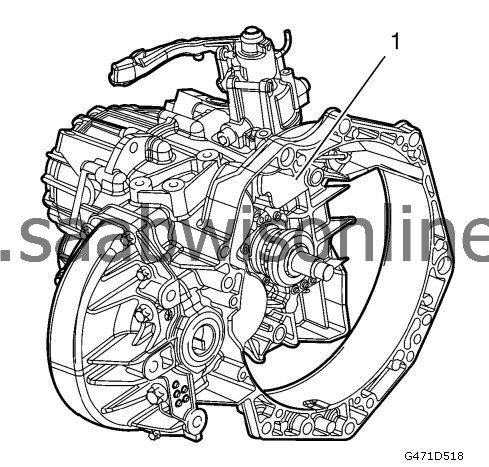
The M32-6 is a 6-speed manual transmission. This manual transmission is an all-synchromesh 3-shaft transmission.
| • |
Compact construction
|
|
| • |
Improved smooth-running performance
|
|
| • |
Better shift quality
|
|
| • |
High torque transmission
|
|
| • |
Low weight
|
|
| Location of the Shafts |
The following cross-sectional diagram shows the location of the respective shafts in the M32-6 transmission, as per the 3-shaft principle.
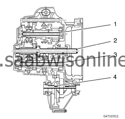
(1) Upper main shaft
(2) Input shaft
(3) Lower main shaft
(4) Differential gear
In this transmission angular cone bearings are used for all shafts. These bearings require a certain amount of play and pretension. The required amount of bearing play and pretension is achieved at the production stage by using shims under the angular cone bearing in the transmission housing.
| Location of the Gear Wheels |
This diagram shows the location of the gear wheels on the respective shaft.
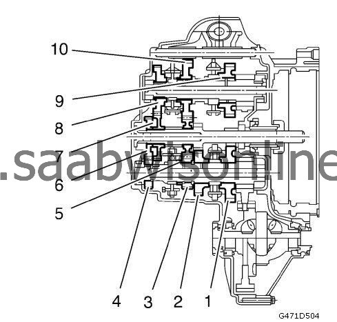
(1) Gear wheel 1
(2) Gear wheel 2
(3) Gear wheel 5
(4) Gear wheel 6
(5) Gear wheel 3/5
(6) Gear wheel 6
(7) Gear wheel 4
(8) Gear wheel 4
(9) Reverse Gear Gearwheel
(10) Gear wheel 3
| Power Flow in the Individual Gears |
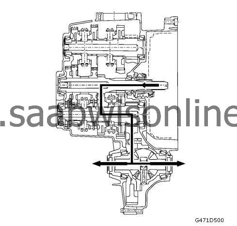
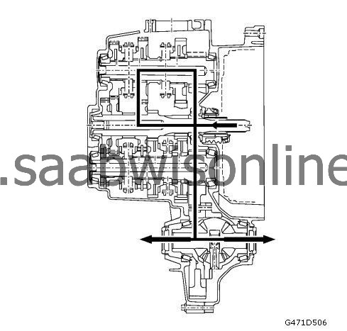
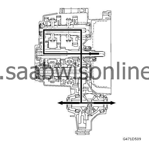
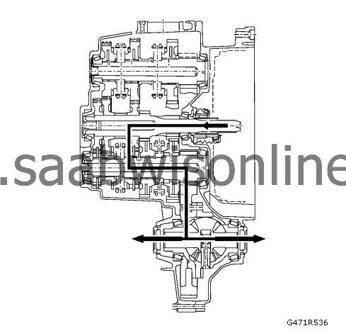
The following diagrams shows the flow of power in the individual gears.
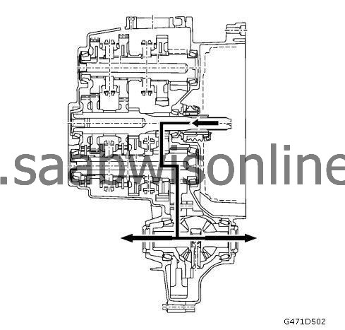
1st gear
2nd gear
3rd gear
4th gear
5th gear
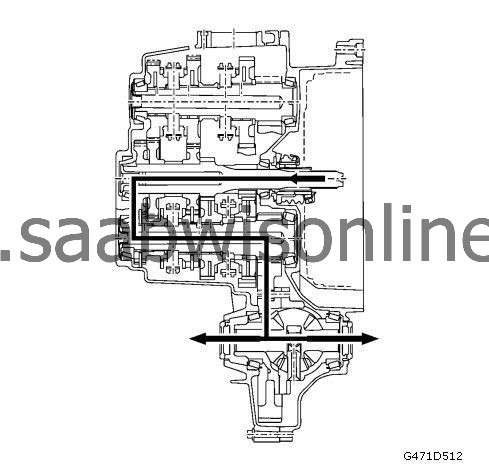
6th gear
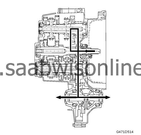
Reverse Gear


