Front Suspension Description and Operation (GNB)
| Front Suspension Description and Operation (GNB) |
HiPerStrut Front Suspension:
The front suspension has 2 primary purposes:
| • |
Isolate the driver from irregularities in the road surface.
|
|
| • |
Define the ride and handling characteristics of the vehicle.
|
|
The front suspension absorbs the impact of the tires travelling over irregular road surfaces and dissipates this energy throughout the suspension system. This process isolates the vehicle occupants from the road surface. The rate at which the suspension dissipates the energy and the amount of energy that is absorbed is how the suspension defines the vehicles ride characteristics. Ride characteristics are controlled by the Electronic Suspension Control system. It individually controls the damping force of each of the 4 shock absorbers.
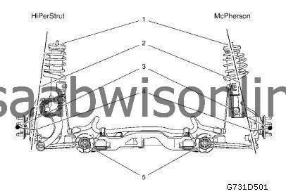
This requires that the steering knuckle be suspended between a lower control arms via the yoke assembly to the strut assembly. The lower control arm outermost point is attached to the yoke assembly and then through the king pin bushing to the steering knuckle. The innermost end of the control arm attached at 2 points to the vehicle frame through semi-rigid bushings. The upper portion of the steering knuckle is attached to the yoke assembly via a ball stud. The yoke assembly then connects to the struts assembly and vehicle body by way of an upper bushing. The steering knuckle is allowed to travel up and down independent of the vehicle body structure and frame.
The advantage of the HiPerStrut front suspension (GNB) over the McPherson-type wheel suspension is less spindle length which leads to:
| • |
Reduced smooth road shake
|
|
| • |
Less torque steer
|
|
| • |
Increased cornering power, no camber loss during cornering
|
|
| • |
Robustness against wheel imbalance
|
|
All in all the HiPerStrut design provides improved ride and handling performance with a premium steering feel.
The design enables bigger wheels.
The design allows camber adjustment with screws on the steering knuckle upper ball stud.

(1) Upper Body Attachment (Same Points)
(2) Kingpin Axis
(3) Wheel Center
(4) Spindle Length
(5) Lower Body Attachment (Same Points)


