Dismantling
| Dismantling |
| 1. |
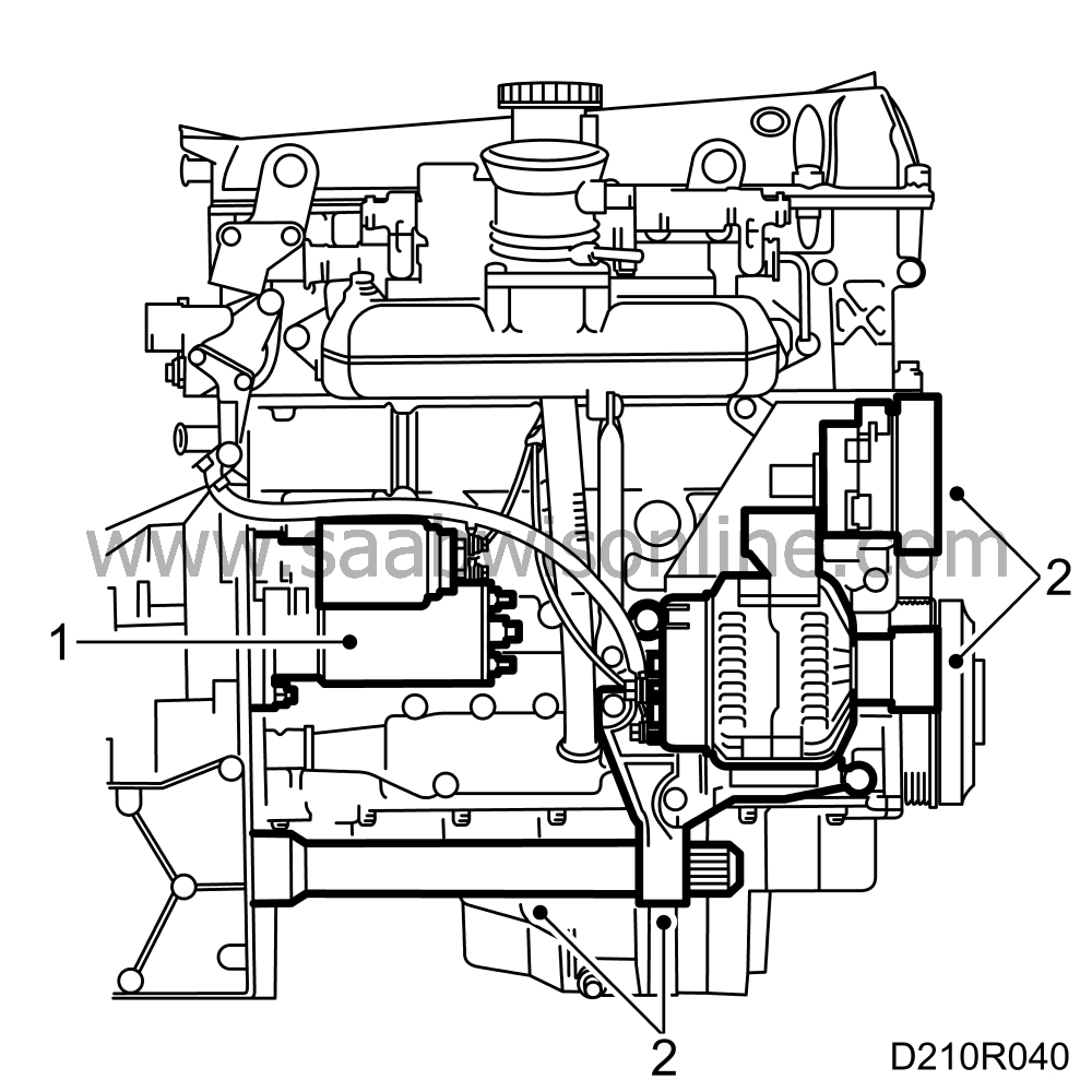
Drain the oil and remove the starter motor.
|
|
| 2. |
Remove the belt tensioner, alternator and support bearing bracket complete with tube and inner drive-shaft joint.
|
|
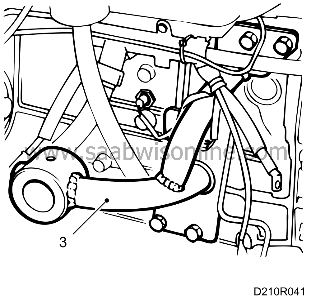
| 3. |
Fit holder 83 95 220 on the engine and lift the power train onto floor stand 78 74 878.
|
|
| 4. |
Remove the protective plate and undo the torque converter retaining bolts (automatic transmission). Rotate the flywheel by means of the crankshaft pulley to bring each bolt up to the opening where it can be removed.
|
|
| 5. |
Secure the torque converter with a holder 87 92 277 (automatic transmission).
|
|
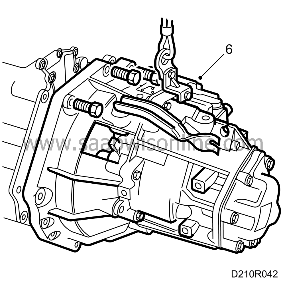
| 6. |
Remove the transmission. Use cable 87 92 442 and holder 87 92392 (automatic transmission)
|
|
| 7. |
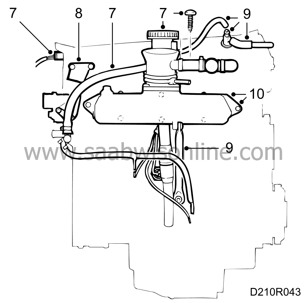
Disconnect the electric leads from the ignition discharge module, remove the oil filler pipe bracket and remove the preheating hoses from the throttle body.
|
|
| 8. |
Remove the bracket for the electric leads.
|
|
| 9. |
Undo the crankcase breather nipple and remove the intake manifold steady bar.
|
|
| 10. |
Remove the intake manifold retaining bolts and lift away the manifold.
|
|
| 11. |
Remove the bracket for the engine mounting.
|
|
| 12. |
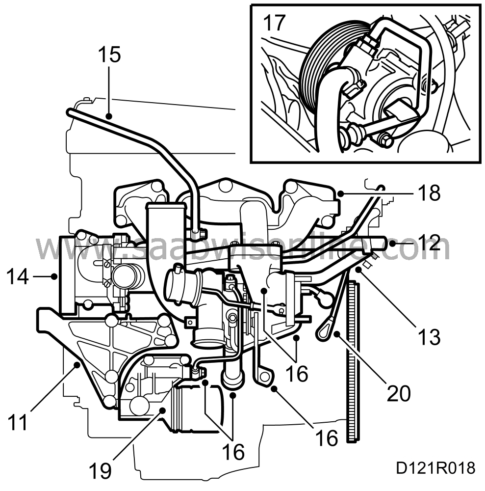
Remove the filler pipe from the expansion tank.
|
|
| 13. |
Remove the heat exchanger pipe.
|
|
| 14. |
Remove the water pump complete with sleeve and O-rings.
|
|
| 15. |
Remove the crankcase breather pipe together with the inlet pipe (turbo).
|
|
| 16. |
Remove the turbo steady bar, disconnect the water and oil pipes (turbo) and remove the turbo unit.
|
|
| 17. |
Remove the power steering pump complete with bracket.
|
|
| 18. |
Remove the exhaust manifold. In regard to the two-piece exhaust manifold, first remove the inner section and then the outer section. Note that spacer sleeves are fitted on the outer studs only.
|
|
| 19. |
Remove the oil filter and adapter housing.
|
|
| 20. |
Remove the crankshaft position sensor.
|
|
| 21. |
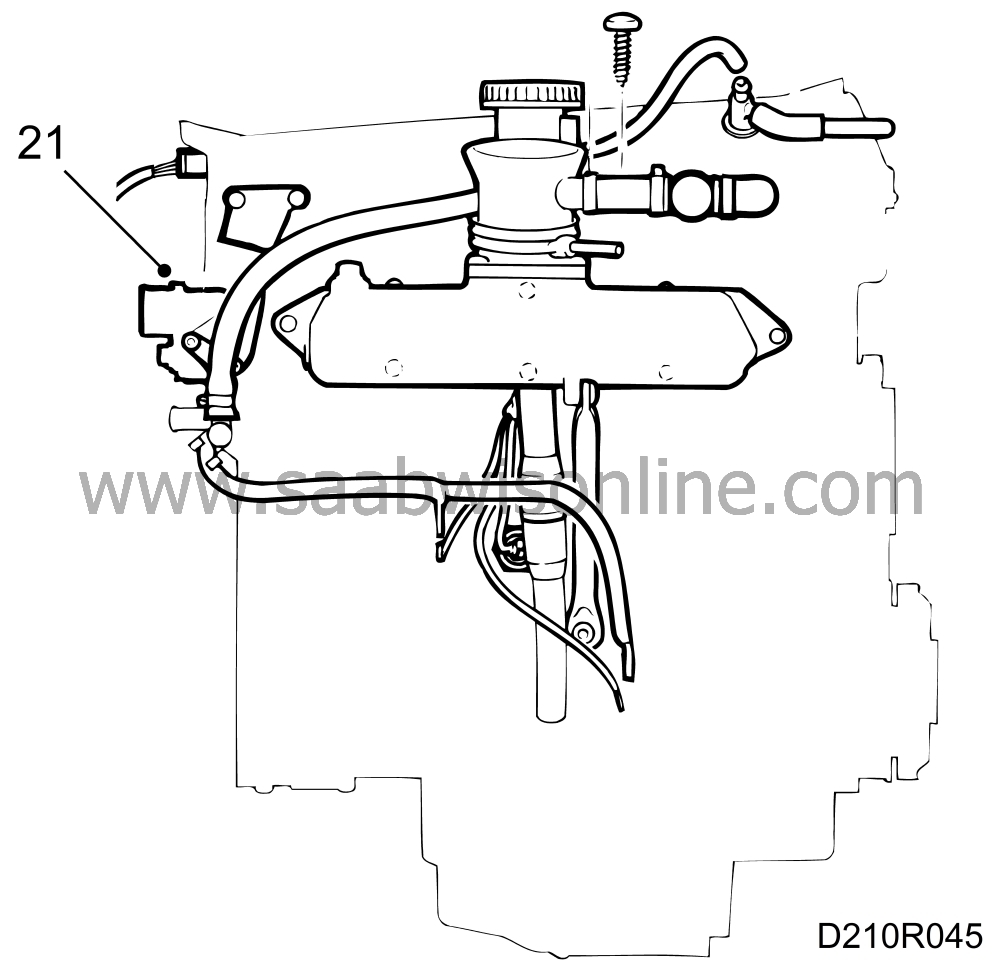
Remove the thermostat housing cover.
|
|
| 22. |
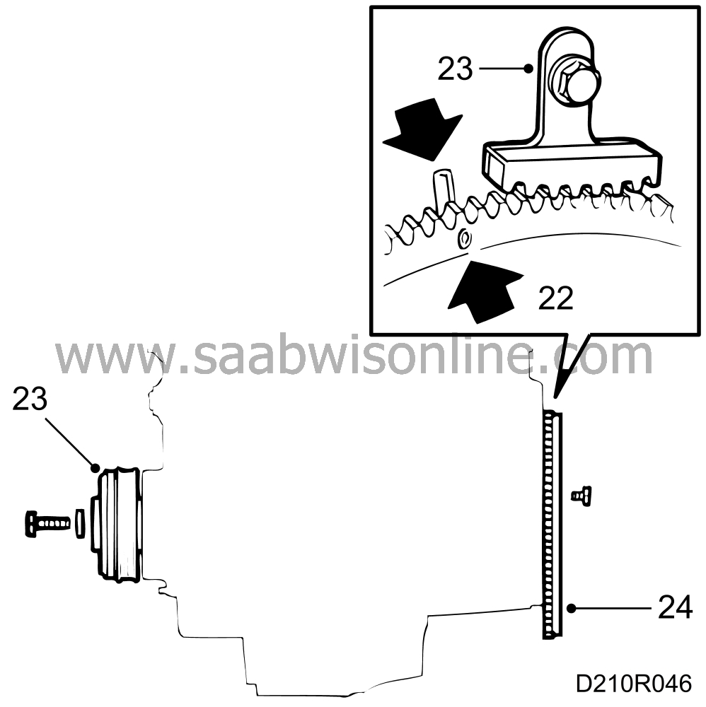
Align the mark (0°) on the flywheel or driver disc with the mark on the end plate.
|
|
| 23. |
Fit flywheel locking segment 83 94 868 and remove the crankshaft pulley.
|
|
| 24. |
Remove the flywheel locking segment and remove the flywheel or driver disc.
|
|
| 25. |
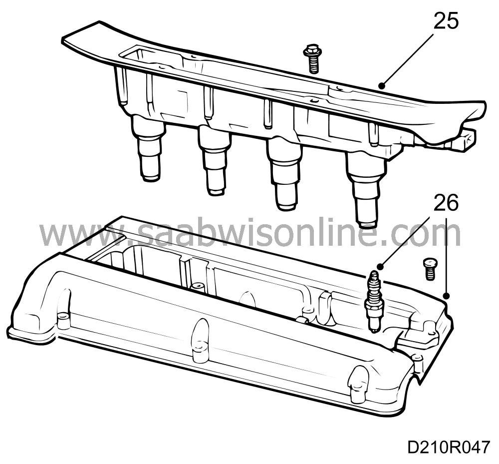
Remove the ignition discharge module or cover plate and disconnect the HT cables (B206i/B234i).
|
|
| 26. |
Remove the spark plugs and camshaft cover.
|
|
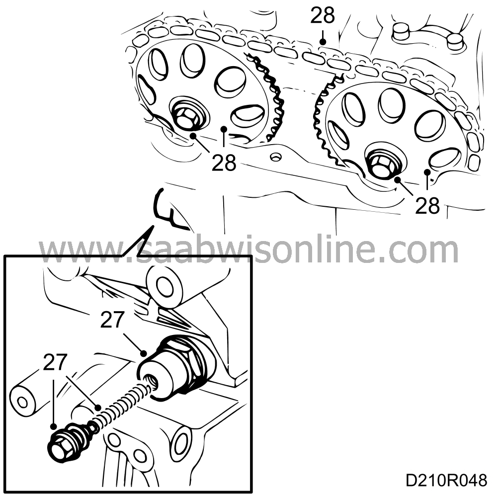
| 27. |
Remove the chain tensioner. First remove the plug with spring, then use a 27 mm socket to remove the tensioner.
|
|
| 28. |
Remove the camshaft sprockets and position the chain so that it will not obstruct removal of the cylinder head.
|
|
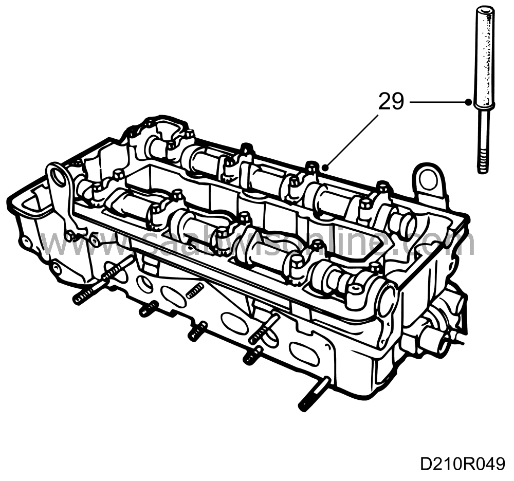
| 29. |
Remove the cylinder head. Start with the timing cover bolts and continue in reverse assembly order. Use protective collar 75 19 531 to collect the bolts.
|
|
| 30. |
Swivel the engine into a suitable position and remove the sump.
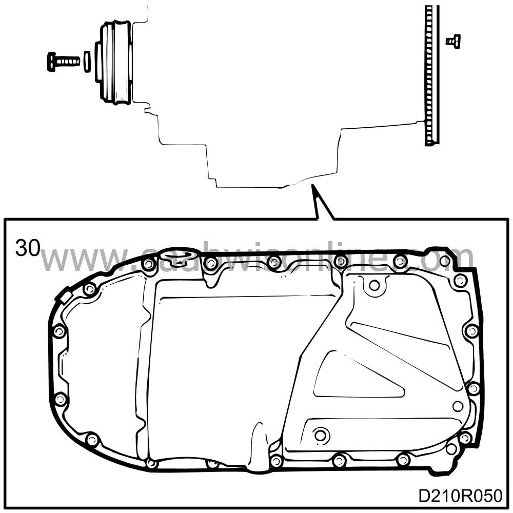
Leave the sump's locating sleeve in the cylinder block. |
|
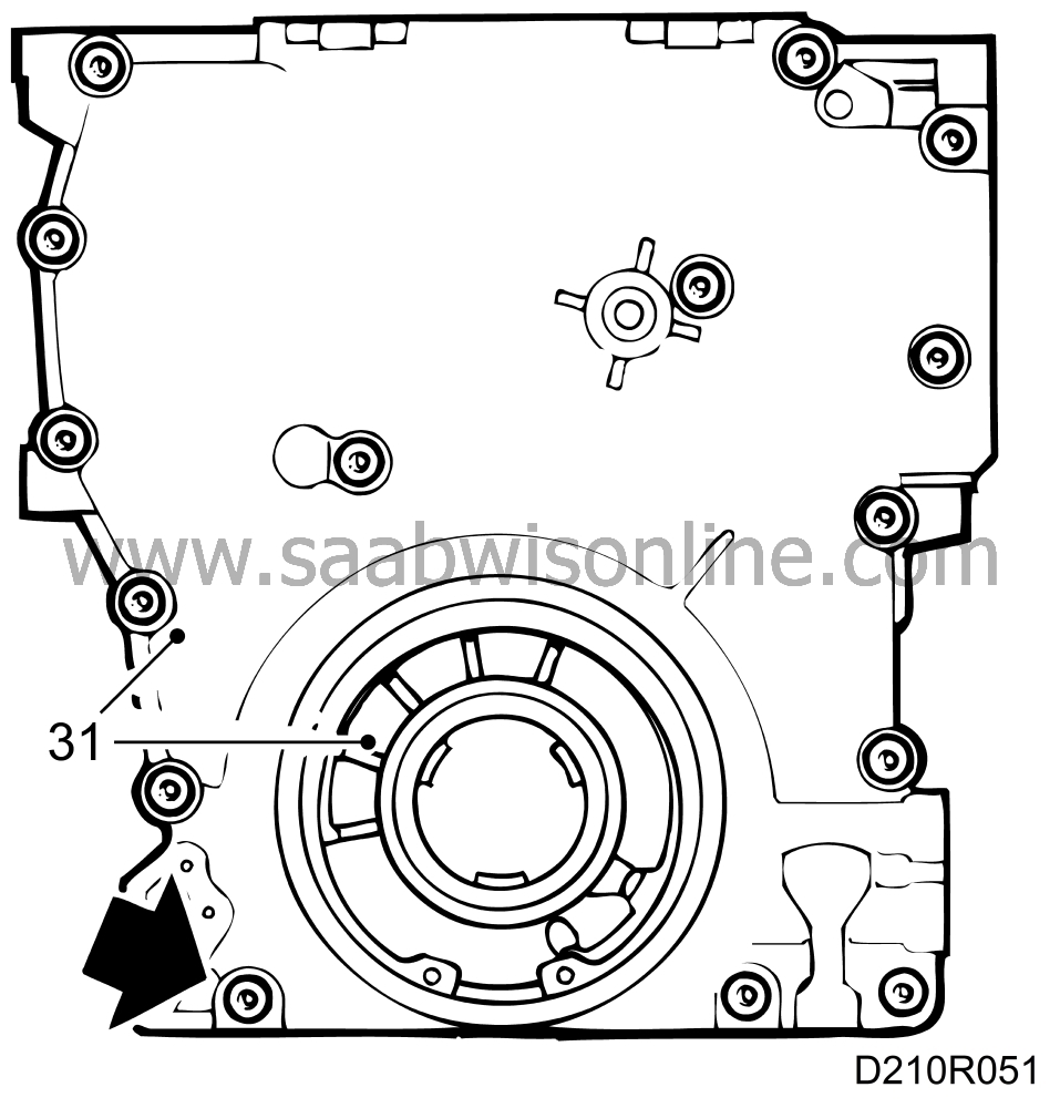
| 31. |
Remove the oil pump and the timing cover.
|
|
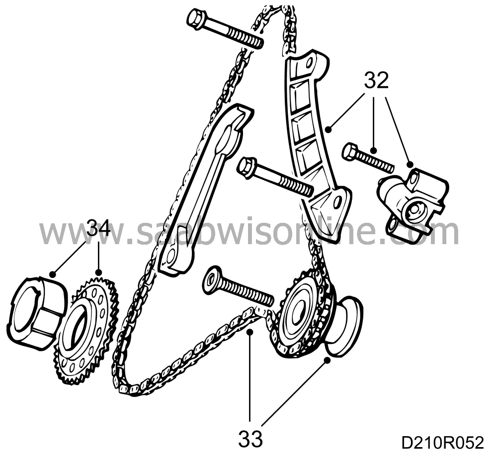
| 32. |
Remove the top chain guide and chain tensioner for the balance-shaft chain.
|
|
| 33. |
Remove the idler sprocket and balance-shaft chain.
|
|
| 34. |
Remove the oil pump driver and sprocket from the crankshaft.
|
|
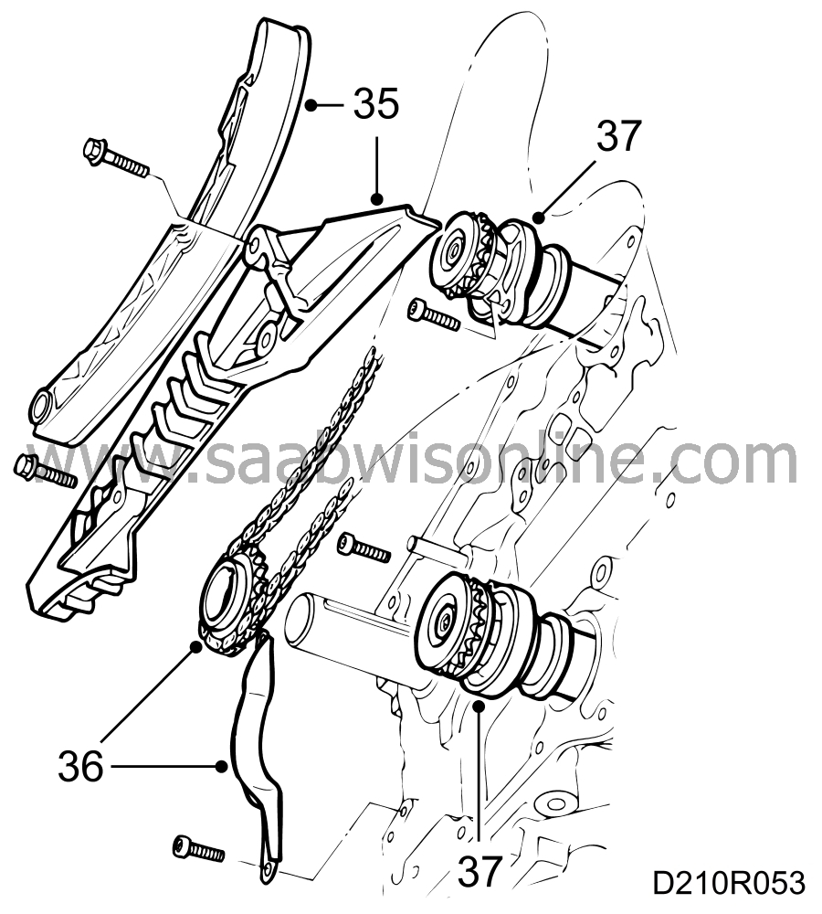
| 35. |
Remove the chain guides for the balance-shaft and timing chains.
|
|
| 36. |
Remove the timing chain guard and remove the chain complete with sprocket.
|
||||||||||
| 37. |
Remove the balance shafts complete with sprockets and bearing housings.
|
|
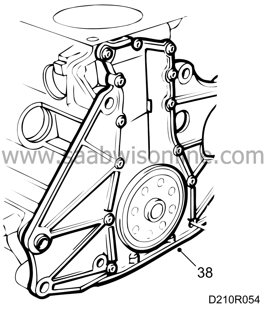
| 38. |
Remove the end plate.
|
||||||||||
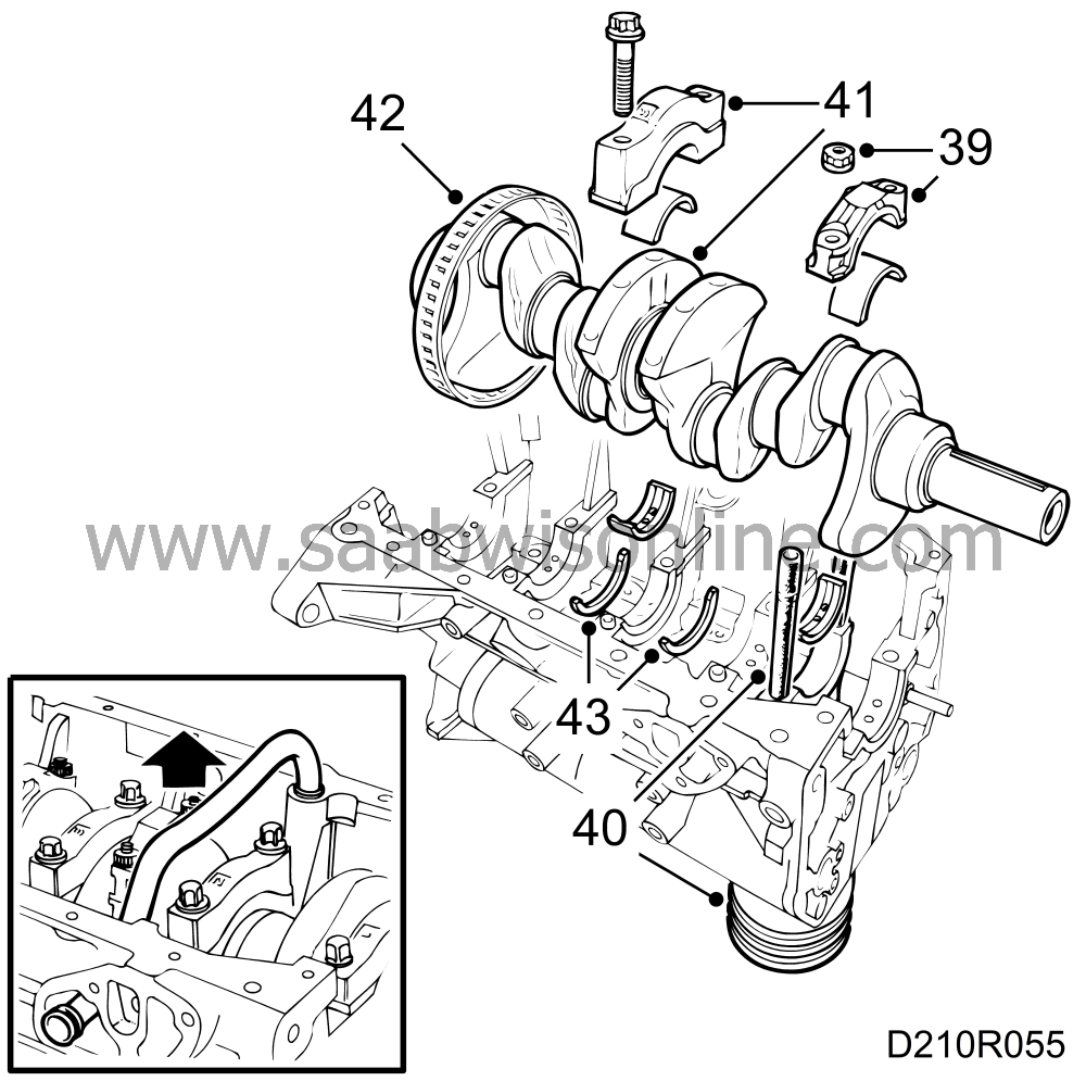
| 39. |
Carefully remove the carbon ridges in the cylinder barrels, invert the engine and remove all big-end bearing caps.
|
|
| 40. |
Fit protective collar 75 19 531 on the studs and press or carefully tap the pistons out of the cylinders.
|
|
| 41. |
Remove the main bearing caps and lift out the crankshaft.
|
||||||||||
| 42. |
Remove the perforated disc.
|
|
| 43. |
Remove all the bearing shells for both the main bearings and big-end bearings. Also remove the two thrust washers from the No. 3 main bearing.
|
|
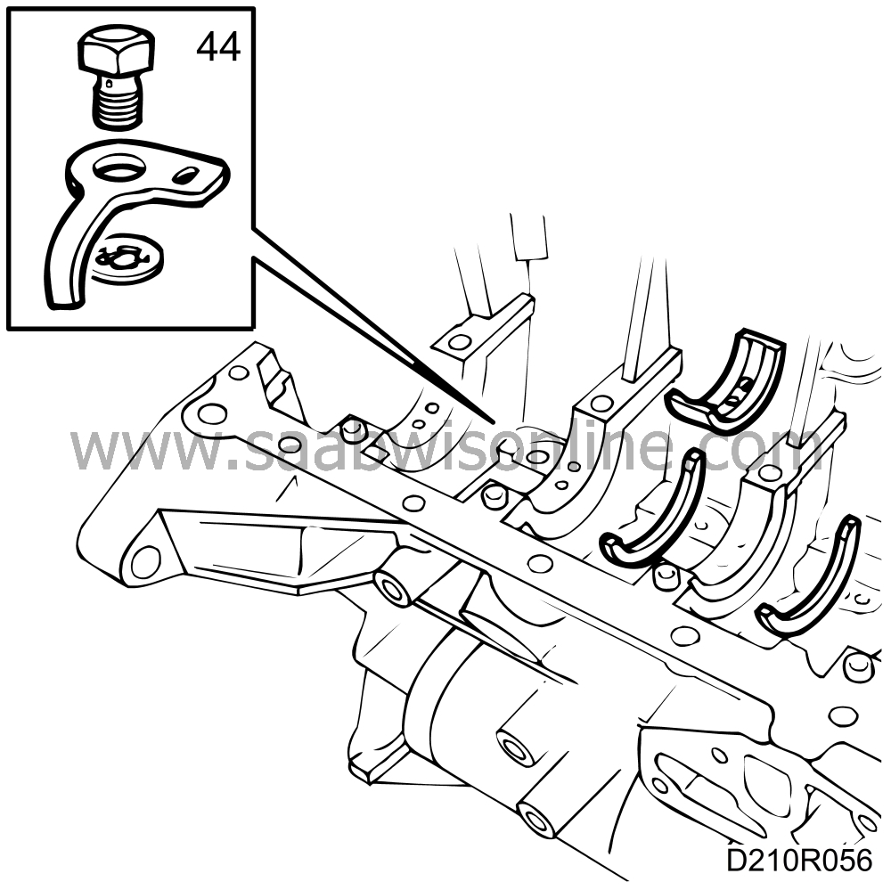
| 44. |
Remove the piston cooling nozzles (B204L).
|
|
This project is supported by memberships and donations. If you use this site, please consider Joining SCNA and/or making a donation.
Our Friends
