Pistons, connecting rods, cylinder bores
|
|
Pistons, connecting rods, cylinder bores
|
|
Within the warranty period
|
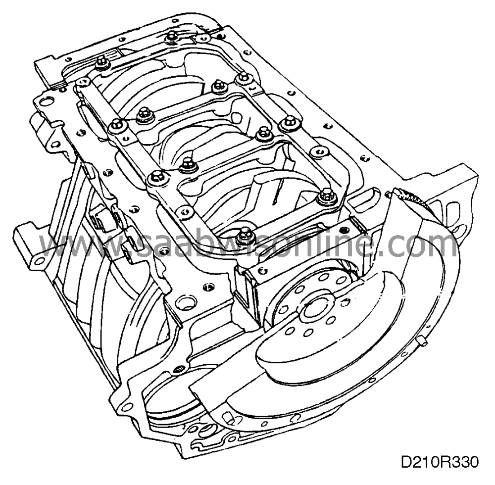
The normal procedure when carrying out work involving piston/connecting rod replacement is to change the cylinder block complete with pistons, connecting rods and crankshaft already fitted. This is known as a "Short-block". For Short-block replacement, see the “Engine” section.
|
After the warranty period has expired
|
After the warranty period has expired, the car owner and garage foreman should jointly decide which of the following methods is most suitable for the case in question:
|
•
|
Alternative 1:
"Short-block" replacement.
|
|
•
|
Alternative 2:
Replacement of piston and connecting rod in the cylinder concerned. After the expiration of the warranty period, replacement of connecting rods in complete sets is not a requirement.
|
|
Removal of pistons (in situ)
|
(Cylinder head removed)
|
1.
|
Scrape away any soot deposits and burrs in the top of the cylinders. Mark the pistons with the cylinder numbers.
|
|
2.
|
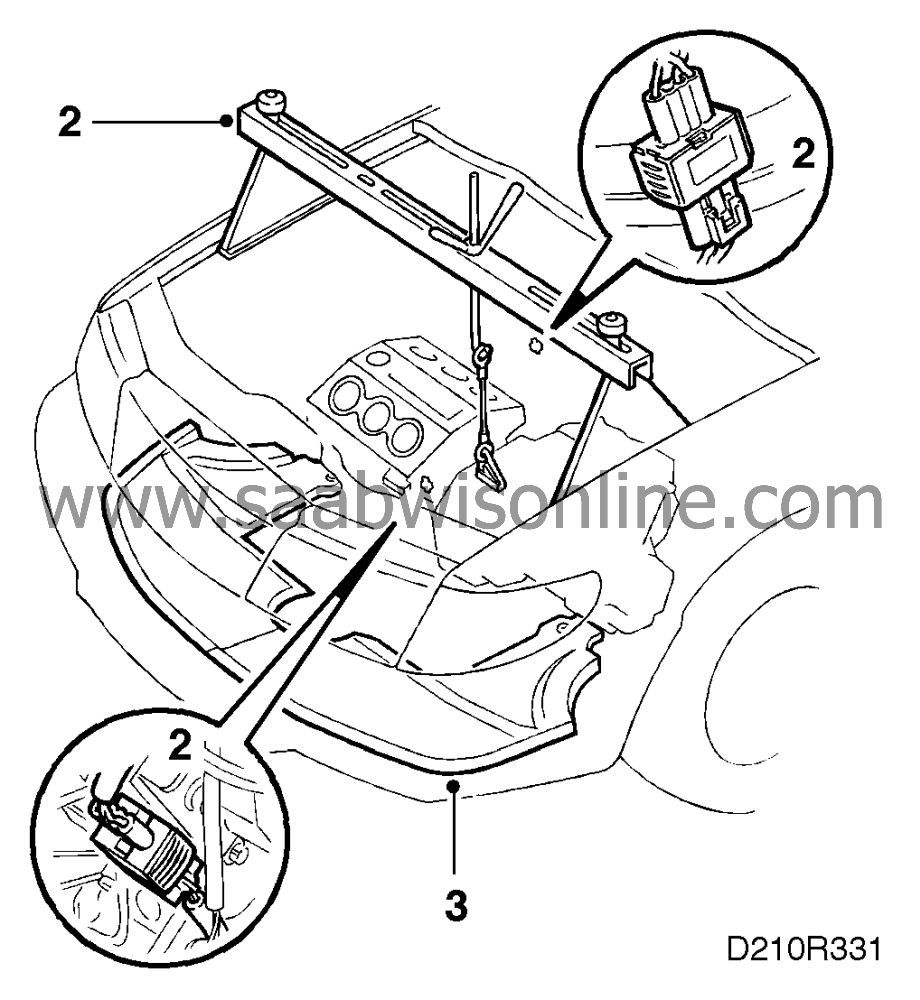
Use yoke 83 94 850 and attach lifting cables 87 92 442 to the gearbox. Unplug the oxygen sensor leads.
|
|
3.
|
Raise the car and drain the oil. Remove the front exhaust pipe and take off the front wheels and spoiler sections.
|
|
4.
|
Detach the steering swivel joints on both sides and the rear engine mounting. Position a lifting table under the engine, raise the lifting table, undo the other screws and lift down the subframe.

|
|
5.
|
Remove the cover plate and the oil sump. Wipe away dripping oil.

|
|
6.
|
Remove the covers from the connecting rods. Push the pistons and the connecting rods from the cylinder bores. Start with 1 and 2.

Mark every piston with the appropriate cylinder number so that they can be placed in their original positions. Fit the bearing cups and the covers loosely on the connecting rods so that the parts do not become mixed.
|
Matching piston rings to a new or rebored cylinder
|
1.
|
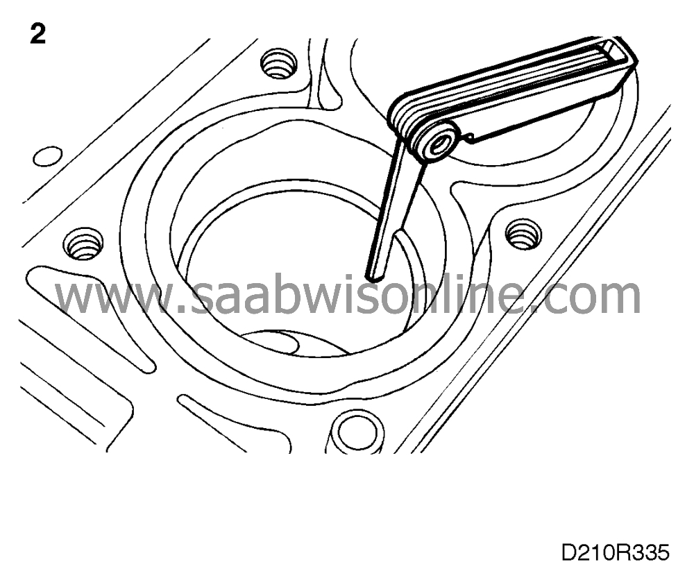
Insert the piston rings into the cylinder bore one by one. Use a piston so that the rings are in the right position.
|
|
2.
|
Measure the ring gap with a feeler gauge, see drawing. If necessary, the gap can be increased with the help of a special file.
Permitted ring gap clearance see "Technical data".
|
Matching piston rings to a worn cylinder
Matching is by the same procedure as with a new or newly bored cylinder, but when matching in a worn cylinder bore the ring must be tested in the lower turn position as the cylinder bore has the smallest diameter there.
Fitting piston rings on pistons
When fitting piston rings on the pistons, use a piston ring clamp as illustrated. Test the piston rings by rotating them in their grooves. Check the clearance in several places. Lubricate the pistons and rings before assembly. Turn the compression rings so that the ring gaps are 120° apart and position them at 90° to the ends of the gudgeon pins. Also make sure that the spring gap in the upper and lower rings of the three-part oil-scraper ring are not aligned, see drawing.

I = The front marking on the top of the piston towards the timing end.
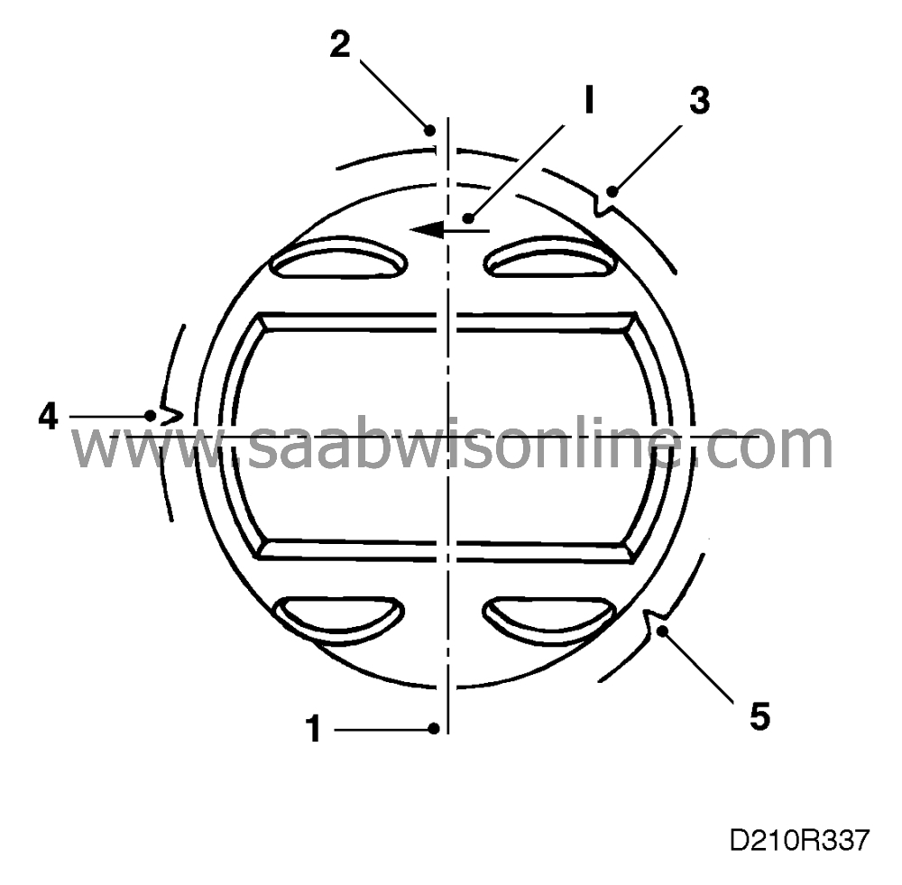
1 = Upper compression ring
2 = Lower compression ring
3 = Steel spacer ring (top oil-scraper ring)
4 = Middle ring (oil-scraper ring)
5 = Steel spacer ring (bottom oil-scraper ring)
|
Fitting of pistons (in situ)
|
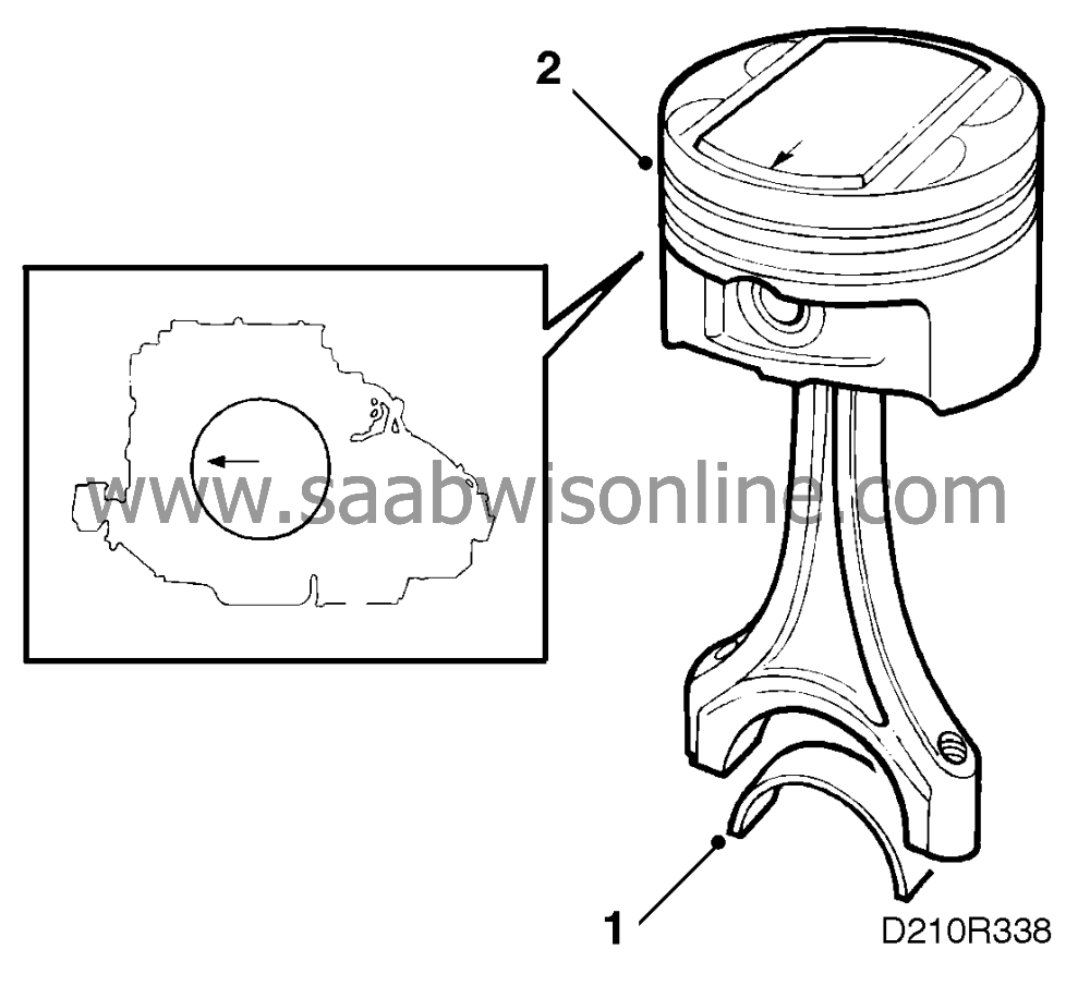
(Cylinder head removed)
Pistons are held in stock as a spare part in standard and oversize. In the case of oversize pistons, the cylinder must be bored to achieve correct piston clearance.
For piston clearance, see "Technical data".
|
1.
|
Place the bearing shells in place in the connecting rods.
|
|
2.
|
Lubricate the piston rings, the bearings and the cylinders.
|
|
3.
|
Fit the piston using fitting tool 83 95 048.

|
|
4.
|
Fit the bearing caps complete with bearings.
Tightening torques
35 Nm (26 lbf ft) + 45 + 15.
|
Important
|
|
The connecting rod and bearing cap contact surfaces must be clean and free from imperfection. If any contact surfaces are damaged, the connecting rod must be replaced as good fit can no longer be guaranteed. Clean contact surfaces with compressed air.
|
|
|
|
|
5.
|
Check that there are no impurities in the sump and clean sealing surfaces. Use washing gasoline.
|
|
6.
|
Apply silicone flange sealant 87 81 841 to all mating surfaces.
|
|
7.
|
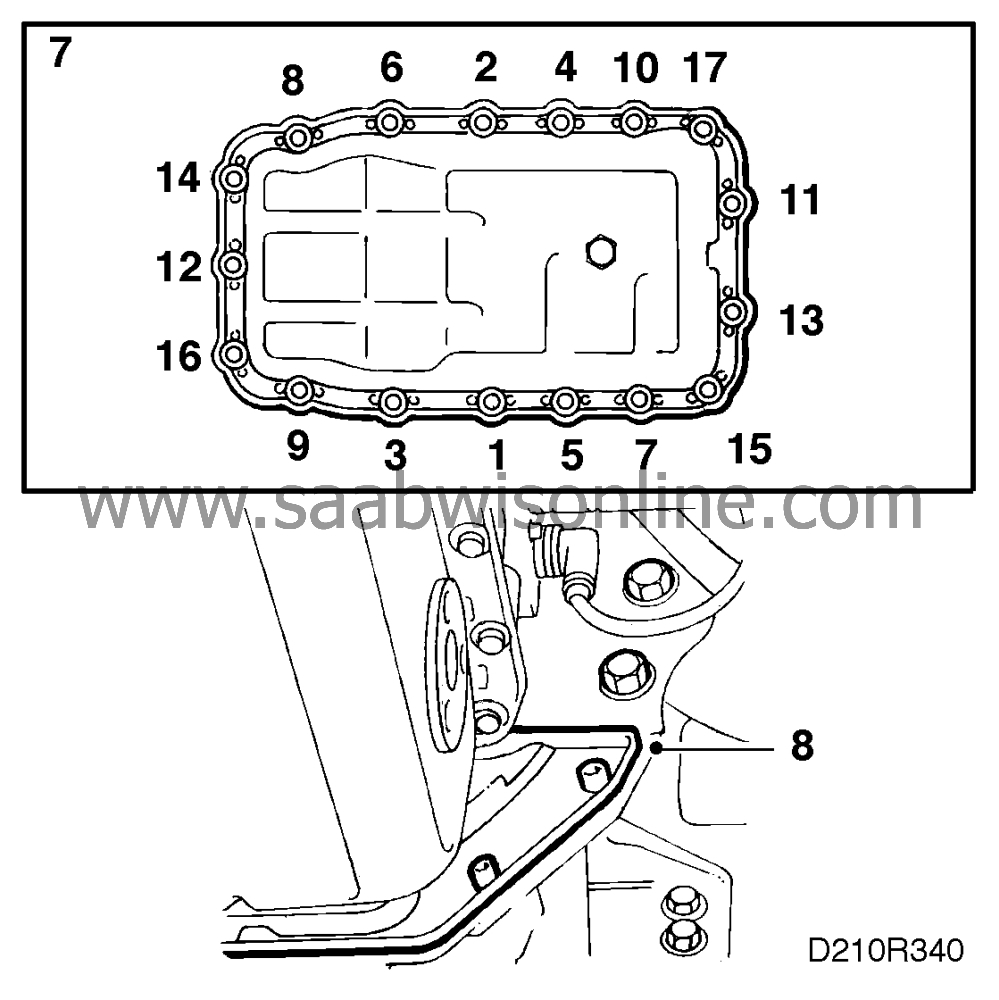
Fit a new gasket and mount the sump using 74 96 268 on the bolts. See drawing for tightening order.
Tightening torque: 15 Nm (11 lbf ft).
|
|
8.
|
Refit the cover plate.
Turning torque 8 Nm (6 lbf ft).
|
|
9.
|
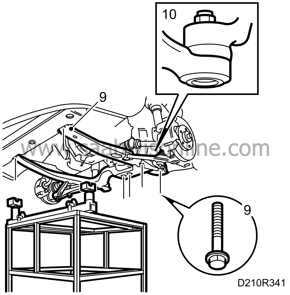
Offer up the sub-frame and bolt it in place.
Tightening torques
front: 115 Nm (85 lbf ft)
middle: 190 Nm (140.6 lbf ft)
- rear: 110 Nm (81.4 lbf ft) + 75°
|
|
10.
|
Refit the steering swivel joint bolts.
Tightening torque: 75 Nm (55.5 lbf ft).
|
|
11.
|
Clean the exhaust pipe joints.

|
|
12.
|
Feed in the front exhaust pipe and bolt it to the exhaust manifold. Use new gaskets.
Turning torque 40 Nm (30 lbf ft).
|
|
13.
|
Bolt together the joint under the car.
Tightening torque 20 Nm (15 lbf ft).
|
Important
|
|
It is very important that all joints are sealed.
|
|
|
|
|
14.
|
Fit the spoiler sections and road wheels.
Tightening torques
110 Nm (81 lbf ft)
|
|
15.
|
Reconnect the oxygen sensor cables and remove the yoke.
|


