Valve gear
| Valve gear |
mounted in holder 83 95 055)
| Important | ||
|
The cylindrical surfaces round the valve springs constitute sealing surfaces for the tappets. These surfaces must not be scratched. The camshafts must come evenly from the bearing seats. |
||
| 1. |
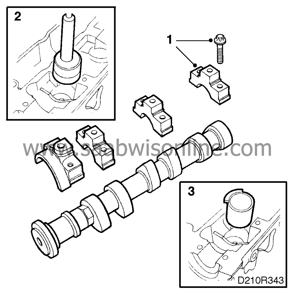
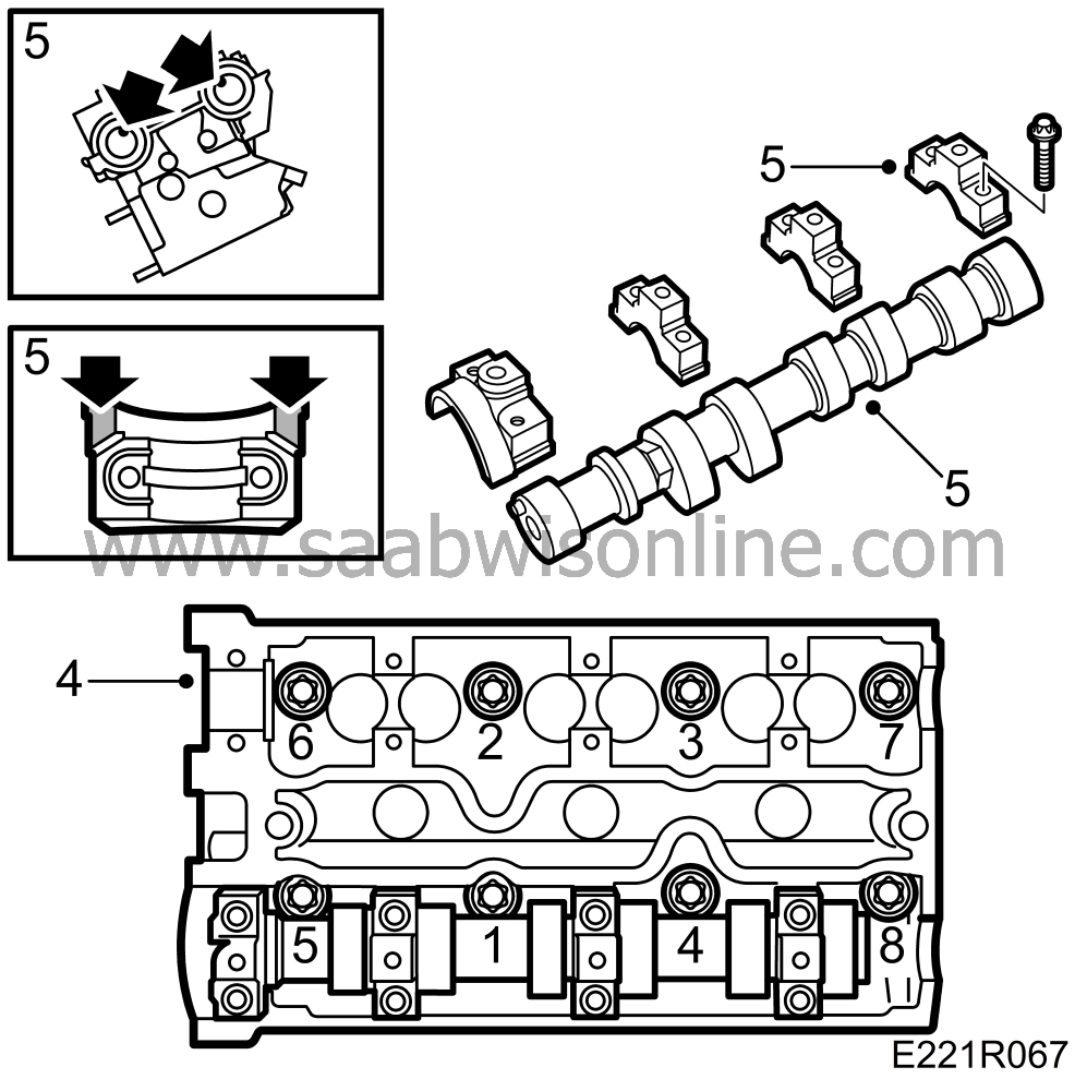
Remove the camshaft bearing caps by loosening the bolts in steps of 1/2 to 1 turn. It is important to finish removal at the bearing cap where the tappets are under load. Then lift out the camshafts. Note the marking.
|
|
| 2. |
Remove the tappets and place them in valve stand 83 93 787 so that they do not become mixed up.
|
|
| 3. |
Fit the protective sleeves 83 95 022.
|
|
| 4. |
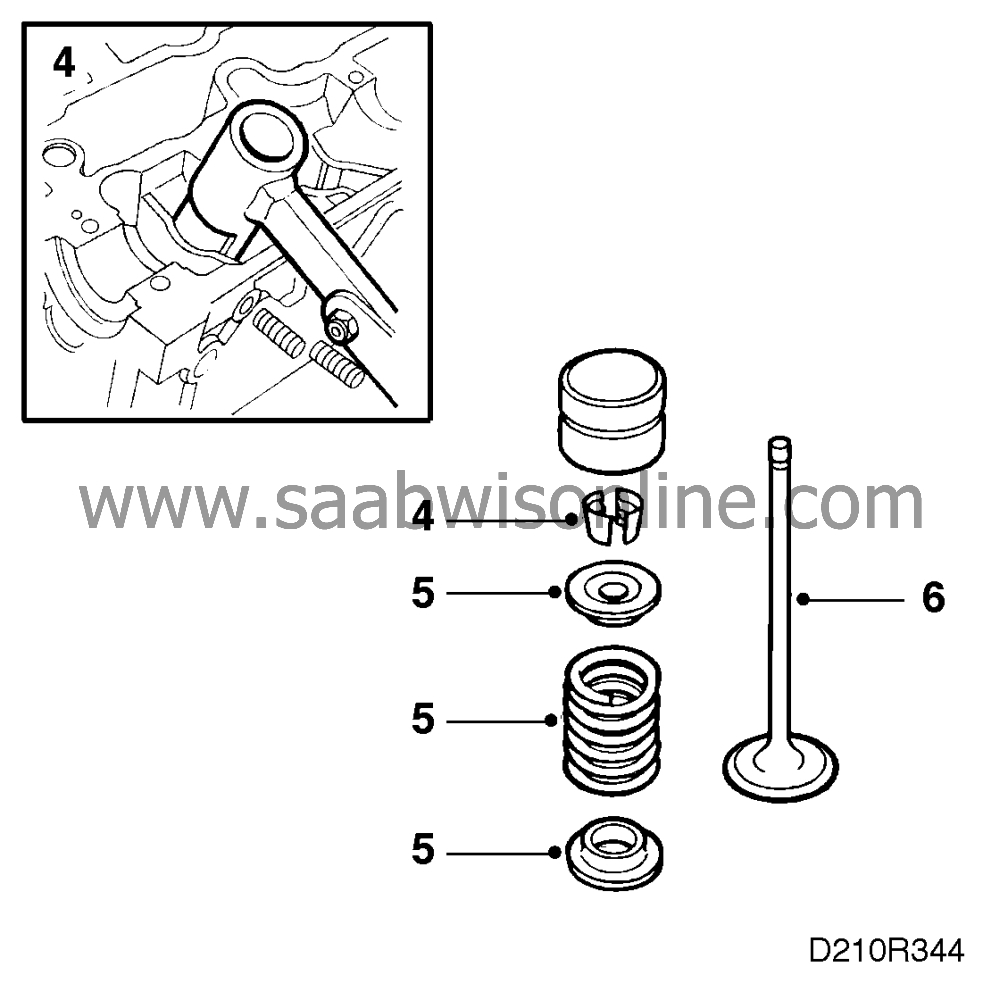
Use valve spring compressor 83 93 761 or 83 95 246 and valve spring depressor 83 93 779 to remove the collets.
|
|
| 5. |
Lift out the spring cap and valve spring. Do not forget the washers.
|
|
| 6. |
Remove the valves and place them in valve stand 83 93 787 so they do not become mixed up.
|
|
| To fit |
(Cylinder head removed,
mounted in holder 83 95 055)
| Important | ||
|
Make sure that the cylinder head is supported so that the valves are not bent when the camshafts are tightened down. |
||
| 1. |
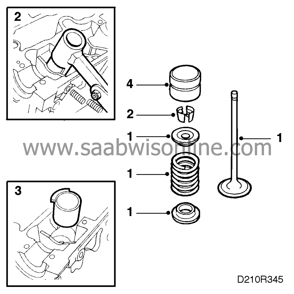
Fit the valves, the washers and the valve springs.
|
|
| 2. |
Refit the spring caps and the collets using valve spring compressor 83 93 761 and anvil 83 93 779.
|
|
| 3. |
Remove the protective sleeves and fit the valve tappets.
|
|
| Valve-gear timing |

(In situ test)
| 1. |
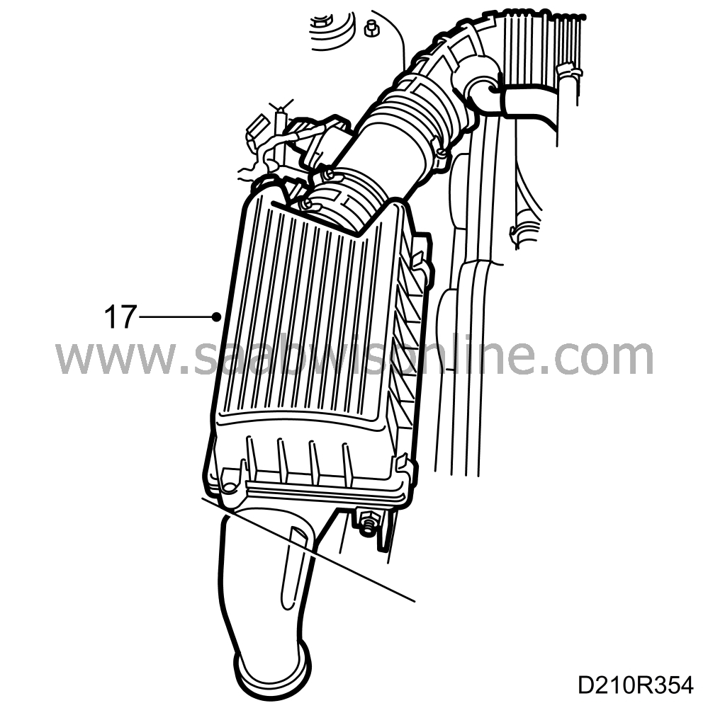
Remove the air cleaner complete with hoses.
|
|
| 2. |
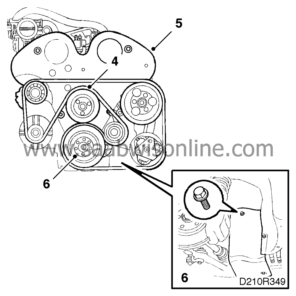
Slightly loosen the bolts for the power steering and coolant pump pulleys. Release the belt tension by turning the locking bolt on the tensioner pulley forward in the car using a 15 mm wrench. Remove the belt from the coolant pump pulley and carefully release the belt tensioner.

|
|
| 3. |
Remove the belt tensioner and the power steering servo pump pulley.
|
|
| 4. |
Remove the water pump pulley (to do this you will have to press the engine towards the left in the car - use the engine bracket as a fulcrum).
|
|
| 5. |
Remove the timing cover.
|
|
| 6. |
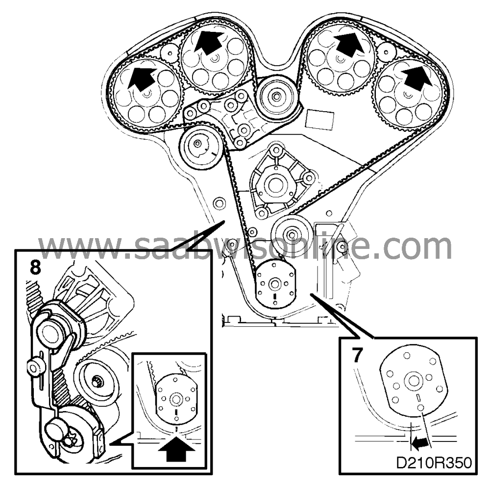
Raise the car and remove the right-hand front wheel and the cover in the wheel housing. Remove the crankshaft pulley (remove the 6 bolts,
not
the centre bolt).
|
||||||||||
| 7. |
Turn the crankshaft in the direction of engine rotation to just before the zero point. The groves on the camshaft sprockets should be slightly ahead of the marks on the rear toothed belt cover.
|
|
| 8. |
Fit locking tool 83 95 006 on the crankshaft and carefully turn the crankshaft in the direction of engine rotation until the arm rests against the coolant pump's flange, and then tighten it.
|
||||||||||
| 9. |
Fit gauge 83 95 006 on camshaft sprockets 3 and 4. The markings on camshaft sprockets 3 and 4 must be exactly aligned with the markings on the gauge.

Fit gauge 83 95 006 on camshaft sprockets 1 and 2. The markings on camshaft sprockets 1 and 2 must be exactly aligned with the markings on the gauge. If the markings are not aligned, the valve-gear timing must be adjusted. |
|
| 10. |
Fit the crankshaft pulley.
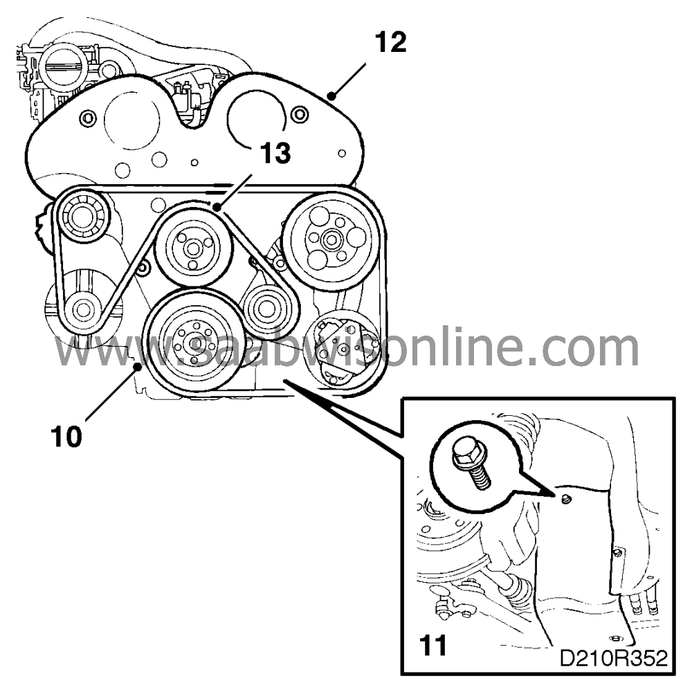
Tightening torque 20 Nm (15 lbf ft). |
|
| 11. |
Refit the cover and fit the wheel.
Tightening torques 110 Nm (81 lbf ft) |
|
| 12. |
Fit the timing cover.
Turning torque 8 Nm (6 lbf ft). |
|
| 13. |
Refit the water pump pulley (to do this you will have to press the engine towards the left in the car - use the engine bracket as a fulcrum).
Turning torque 8 Nm (6 lbf ft). |
|
| 14. |
Refit the power steering pump pulley.

Tightening torque 20 Nm (15 lbf ft). |
|
| 15. |
Refit the belt tensioner.
Turning torque 40 Nm (30 lbf ft). |
|
| 16. |
Release the tension on the belt tensioner by turning the locking bolt on the belt tensioning pulley forward in the car, using a 15 mm wrench. Carefully release the belt tensioner and check all pulleys.
|
|
| 17. |
Refit the air cleaner complete with hoses.
|
|
| To remove, valve-stem seals |
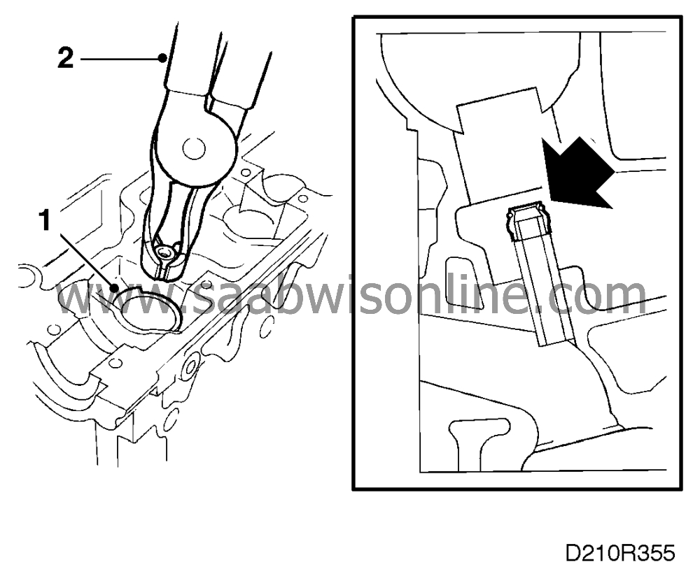
(Cylinder head, camshafts and tappets removed)
| 1. |
Fit protective sleeves 83 95 022 to protect the tappet cylinders.
|
|
| 2. |
Remove the seals from the valve guides using pliers 83 94 157.
|
|
| To fit, valve-stem seals |

(Cylinder head, camshafts and tappets removed)
| 1. |
Fit the seals with tool 83 95 071. The seal is placed in the tool and then the tool is placed in the valve guide. If the valve is fitted use the valve stem as a guide.
|
|
| 2. |
Tap the seal into position using a plastic mallet and remove the plastic sleeves.
|
|
| To remove, valve-stem seals (in situ) |
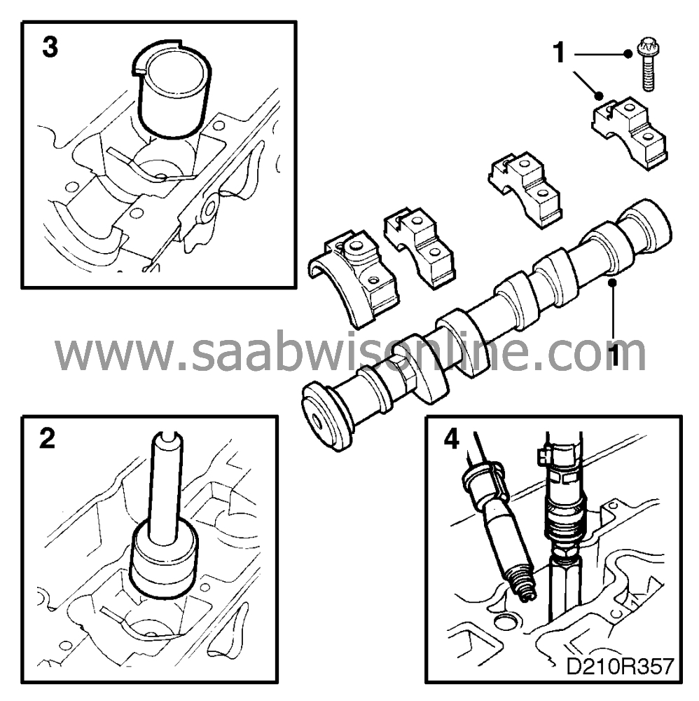
This same method can also be used for the replacement of valve springs, valve caps or collets.
| 1. |
Remove the intake manifolds, camshaft covers and camshafts. See the “Cylinder head” section.
|
||||||||||
| 2. |
Lift out the tappets, using magnetic tool 83 91 401.
|
|
| 3. |
Fit plastic sleeves 83 95 022 around the valve springs to protect the sealing surfaces of the tappets.
|
|
| 4. |
Turn the crankshaft to bring the piston in the cylinder concerned up to the top dead centre position. Use flywheel locking segment 83 94 868 to prevent the crankshaft from turning, unscrew the spark plug from the cylinder in question and fit air nipple 83 94 173 in the spark plug hole. Connect a compressed air supply and pressurize the piston and valves.
|
|
| 5. |
Hold removal tool 83 94 181 against the valve head and in line with the valve stem. Strike the tool smartly with a hammer. This should free the collets from the valve and they will then be collected in the tool as it is removed.
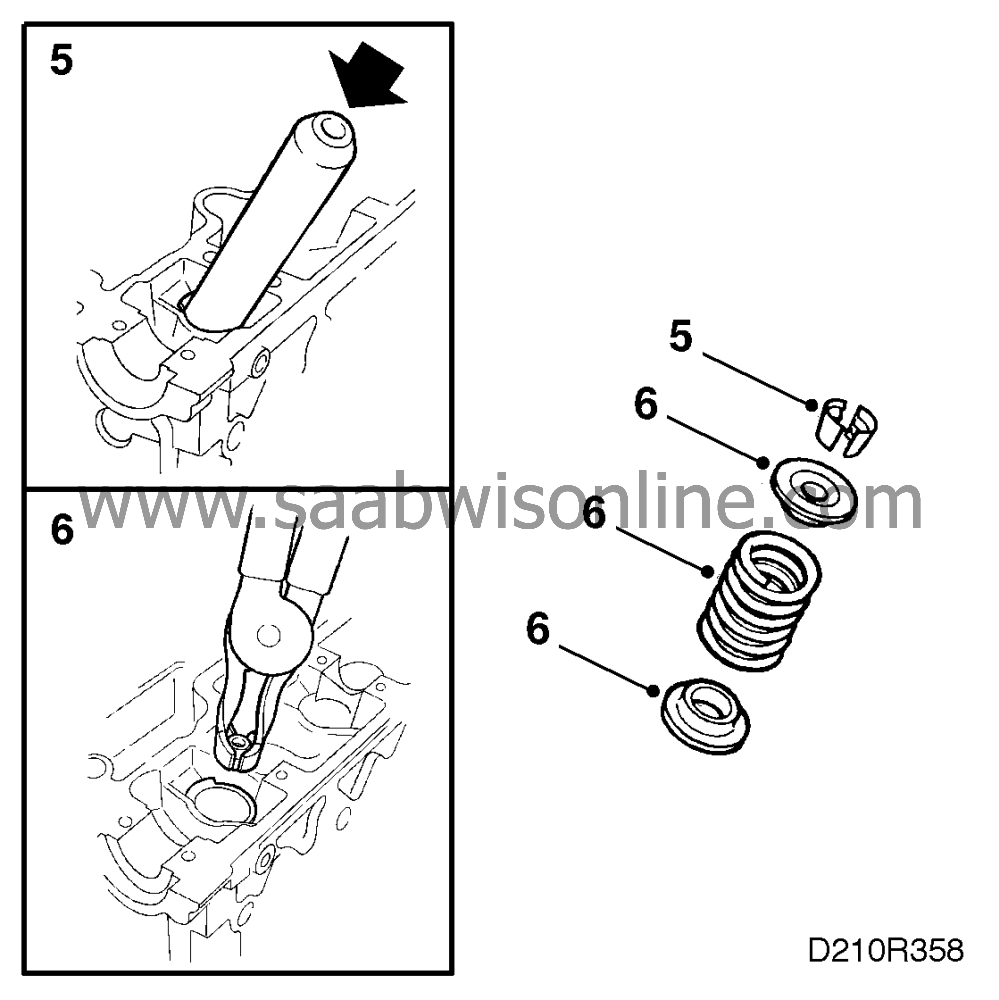
|
|
| 6. |
Lift out the spring cap and valve spring. Remove the valve stem seal using pliers 83 94 157.
|
|
| To fit, valve-stem seals (in situ) |
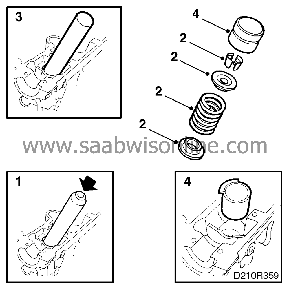
| 1. |
Fit the seal to the valve. Use tool 83 95 071. Use a plastic mallet to tap the seal carefully into position.
|
|
| 2. |
Fit the spring and spring cap and position the collets in the groove in the spring cap.
|
|
| 3. |
Carefully tap the collets home using a hammer, assembly tool 83 94 181 and sleeve 83 94 207. Disconnect the compressed air, remove the compressed-air nipple and the flywheel locking segment. Refit the spark plugs.
Tightening torque 25 Nm (18.5 lbf ft). |
|
| 4. |
Remove the plastic sleeves and fit the tappets.
|
|
| 5. |
Rotate the crankshaft to 60° BTDC, refit the camshafts, valve covers and intake manifolds. See the “Cylinder head” section.
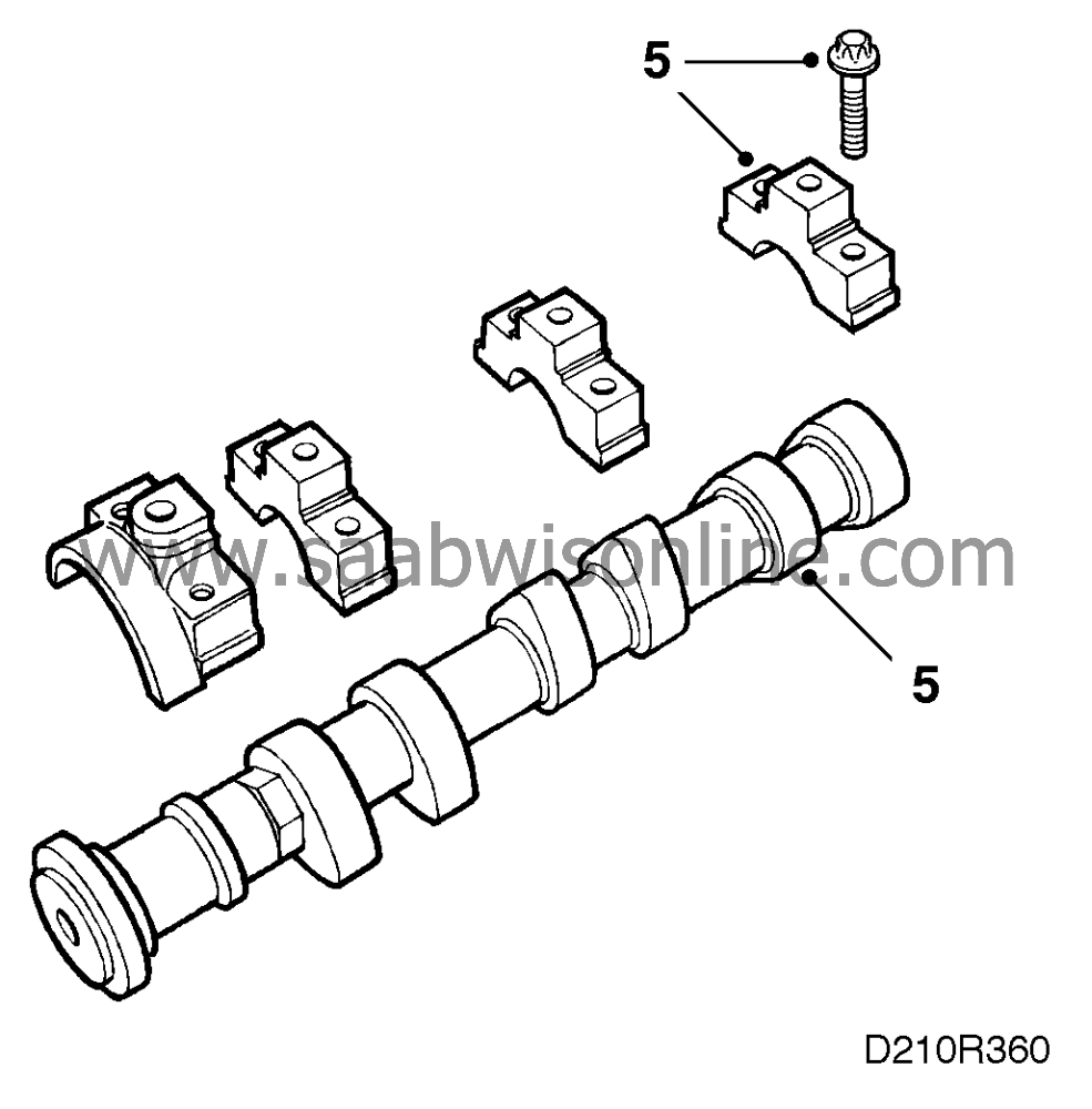
Set the valve-gear timing. |
|
| Valve guides |

The valve guides cannot be replaced and must be reamed to oversize. As consequence, the valve must be replaced with one of appropriate size.
Use reamer 83 95 089.
| Valve seats |
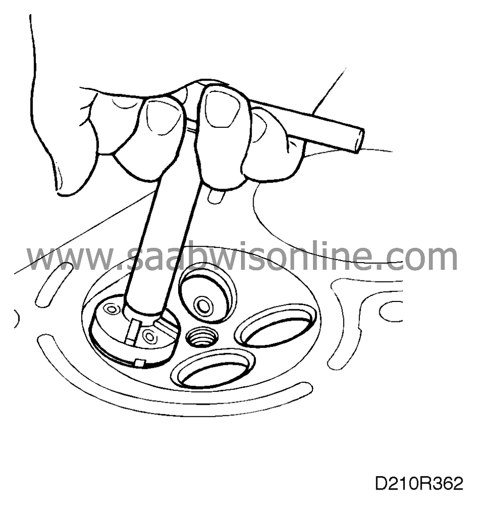
For regrinding the valve seats, use a cutter set consisting of T-wrench, guide spindle 83 95 097 and cutters 78 61 040 (45), 83 93 936 (60) and 83 95 105 (70).
Valve seat angle: 45°
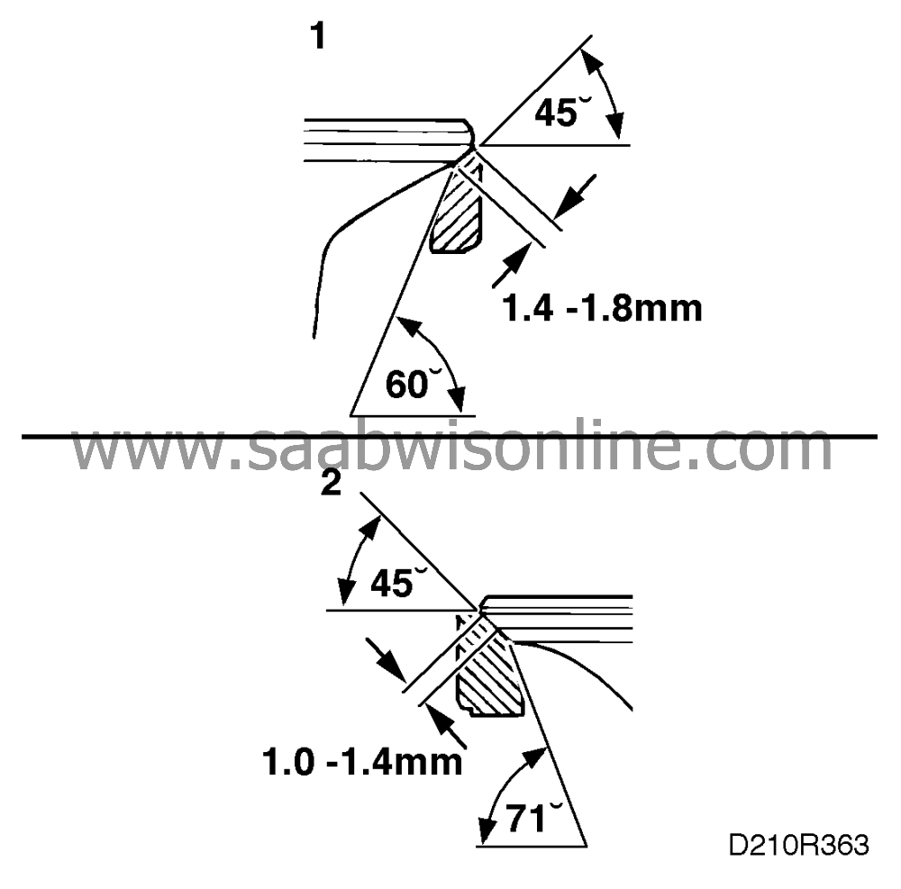
Regrinding angle: 60° (exhaust) (1)
Regrinding angle: 70° (intake) (2)
Valve seat width:
Exhaust valve 1,4-1,8 mm (1)
Intake valve 1,0-1,4 mm (2)

