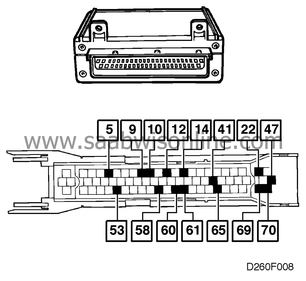
Measurement results control module connections (ICE)
| Measurement results control module connections (ICE) |
| Remember: |
| • |
If nothing else is stated, all voltage measurements should be carried out with all components connected and with the ignition key in the drive position.
|
|
| • |
Measurements should be carried out via the Breakout box (BOB) connected between the control module and the control module's connector.
|
|
| • |
Some of the measurements should be carried out with the engine idling.
|
|
| • |
Several voltage levels should be seen as guides. Use common sense when you judge a recorded value as correct or wrong.
|
|
| • |
If a measurement result is wrong, use the wiring diagram to find out which cables, connectors or components should be checked further.
|
|
The table below only shows the pins which concern the cooling system.
|
Pin
|
Colour
|
Component/function
|
Measurement conditions
|
In/Out
|
Measure-ment result
|
Between X-Y
|
|
5
|
|
Coolant temperature sensor
|
|
In
|
about 0-12 V
|
5-58
|
|
9
|
|
Relay, radiator fan high speed
|
Radiator fan high speed activated
|
Out
|
12 V
|
47-9
|
|
10
|
|
Idling increase signal
|
Idling increase activated
|
Out
|
12 V
|
47-10
|
|
12
|
|
Relay, radiator fan low speed
|
Radiator fan low speed activated
|
Out
|
12 V
|
47-12
|
|
14
|
|
Coolant temperature signal (main instrument 2)
|
|
Out/ PWM
|
about 122 Hz 8-92 %%duty
|
14-70
|
|
22
|
|
Pressure switch radiator fan A C
|
If pressure switch is closed (>15 bar)
|
In
|
12 V
|
47-22
|
|
41
|
|
Supply +54
|
Ignition key in drive position
|
In
|
12 V
|
41-70
|
|
47
|
|
Supply +30
|
Always
|
In
|
<0.5 V
|
B+-47
|
|
53
|
|
Signal ground
|
Engine running
|
In
|
<0.1 V
|
53-Batt-
|
|
58
|
|
Coolant temperature sensor, ground side
|
Always
|
In
|
12 V
|
47-58
|
|
60
|
|
Diagnosis
|
Diagnostics instrument not connected Diagnostics instrument connected + contact with ICE
|
In/Out
|
0 V 12 V
|
60-70
|
|
61
|
|
Coolant temperature signal (main instrument 1)
|
|
Out
|
500 Hz 8-92 %%duty
|
61-70
|
|
65
|
|
Power B
|
Key in position B
|
In
|
12 V
|
65-70
|
|
69
|
|
Pressure switch A C cool
|
Pressure switch closed (>22 bar)
|
In
|
12 V
|
47-69
|
|
70
|
|
Power ground
|
Engine running
|
In
|
<0.1 V
|
70-Batt-
|


