P0122,P0123
Symptom: CHECK ENGINE lamp (MIL) on
Throttle position sensor, input to control module
low/high,
no continuity or shorting to ground/batt+

Fault symptom
CHECK ENGINE lamp (MIL) on
Condition
Voltage from sensor lower than 0.1 V or higher than 4.95 V.
|
Note
|
|
If there is no continuity in the circuit, the control module will
assume a value corresponding to a throttle opening of
30%%.
|
|
1.
|
Check the operation of the
position sensor by using the ISAT command
"THROTT POS SENSOR" in the "READ FUNCTIONS" menu
With the ignition switch in the Drive position,
check that the correct throttle opening is displayed, as
follows:
- approx. 12%%(0.5 V) when idling, increasing as the
accelerator is depressed to approx. 95%%(4.5 V) at full throttle.
If correct readings are displayed, proceed to point 5.
|
|
2.
|
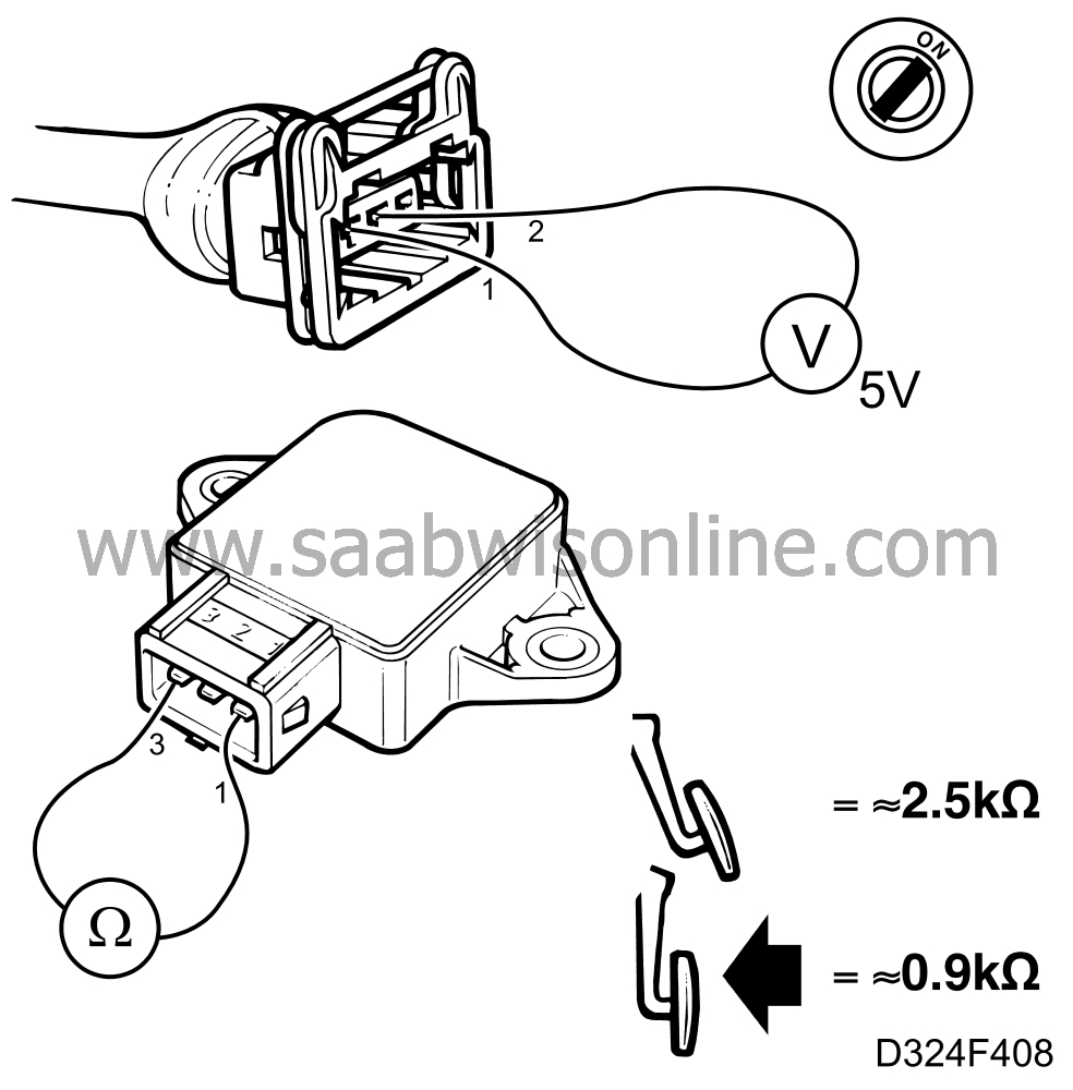
Unplug the connector from the throttle position sensor and, with
the ignition switch in the Drive position, check that the voltage
across pins 1 and 2 of the connector is about 5 V.


If it is not, continue with point 3.
If the voltage is OK, check the resistance of the
sensor by taking a reading across pins 1 and 3. The resistance should
decrease smoothly and successively, without any jumps or breaks, from
about 2.5 kilo-ohms at idling speed to about 0.9 kilo-ohms at full
throttle.
In the event of incorrect resistance, change the
throttle position sensor.
If the position sensor is OK, continue with the next point.
|
|
3.
|
Switch off the ignition and connect a BOB between the MOTRONIC
control module and its wiring.

Turn the ignition switch to the Drive position and
check the voltage from the sensor by taking a reading across pins 12
and 30.
The correct voltage is about 5.0 V.
If the voltage is not correct, proceed to point 5.
If the voltage is correct, check the lead between pin 12 (5
V supply) of the control module and pin 1 of the throttle position
sensor. Also check the lead between pin 30 (sensor ground) of the
control module and pin 2 of the sensor for continuity/
shorting.
|
|
4.
|
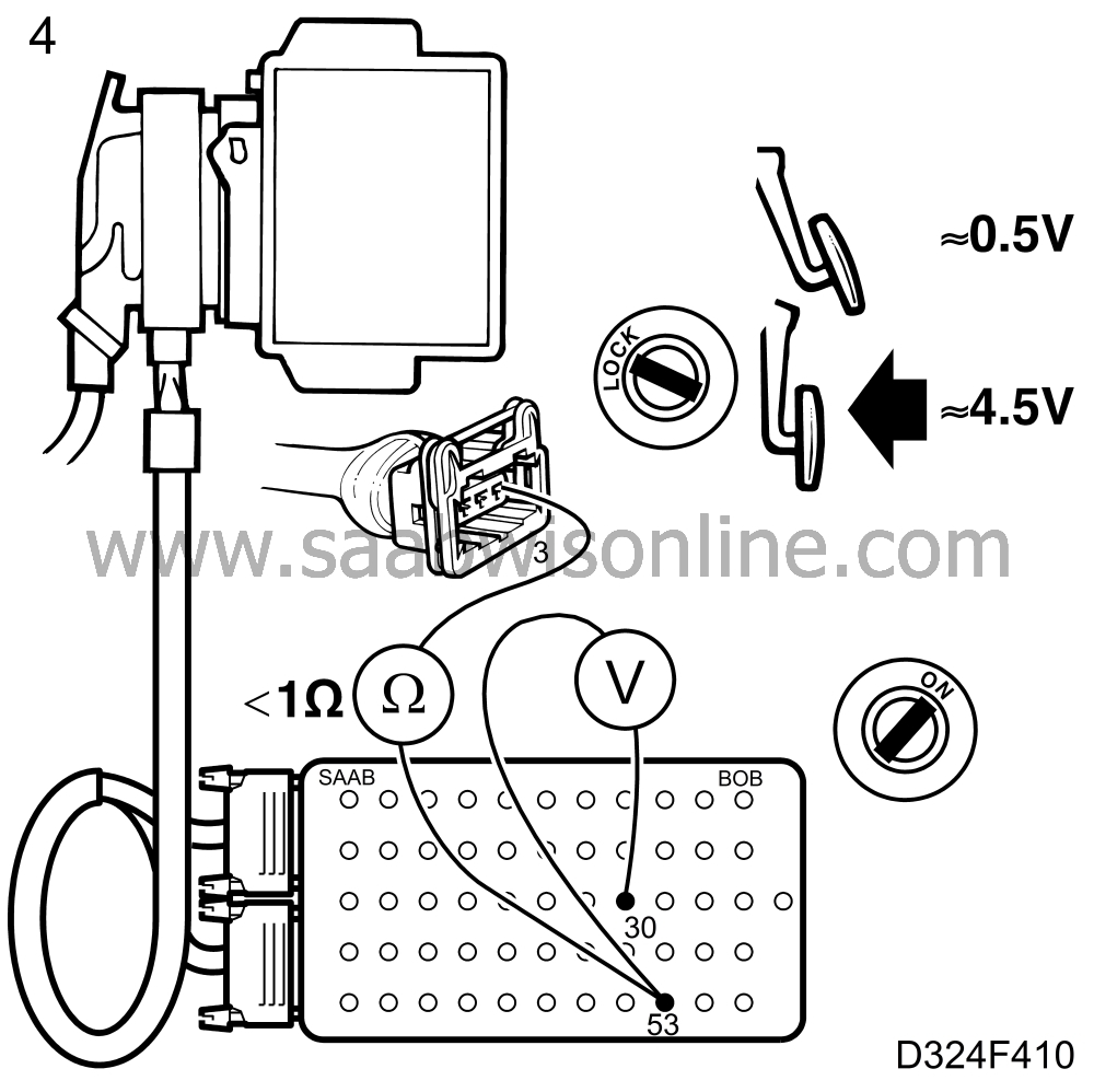
With the throttle position sensor connector plugged in and with the
ignition switch in the drive position, check the voltage across pins 30
and 53 of the control module.

The correct voltage is about 0.5 V at idling speed and
about 4-5 V at full throttle.
If the voltage is not OK, check the wiring and/or
connectors between pin 53 of the control module and pin 3 of the
throttle position sensor for continuity/shorting.
|
|
5.
|
Clear all trouble codes and drive the car to check whether any trouble
codes are generated afresh. If they are, turn to
 for further
diagnostic instructions.
|

 for further
diagnostic instructions.


