Door switches
| Door switches |
| 1. |
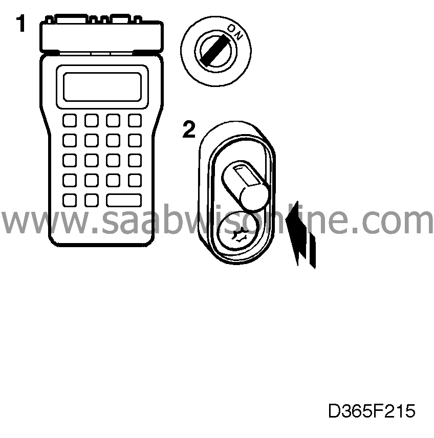
Plug in the scan tool and select
"READ FAULT CODES" from the menu. If any trouble codes are present, continue on
 .
.
|
|
| 2. |
Select "READ VALUES" from the menu and then "DRIVER DOOR" or
"PASSENGER DOOR". Open and close the driver's door or the passenger doors.
Read the scan tool display.
|
||||||||||
| 4. |
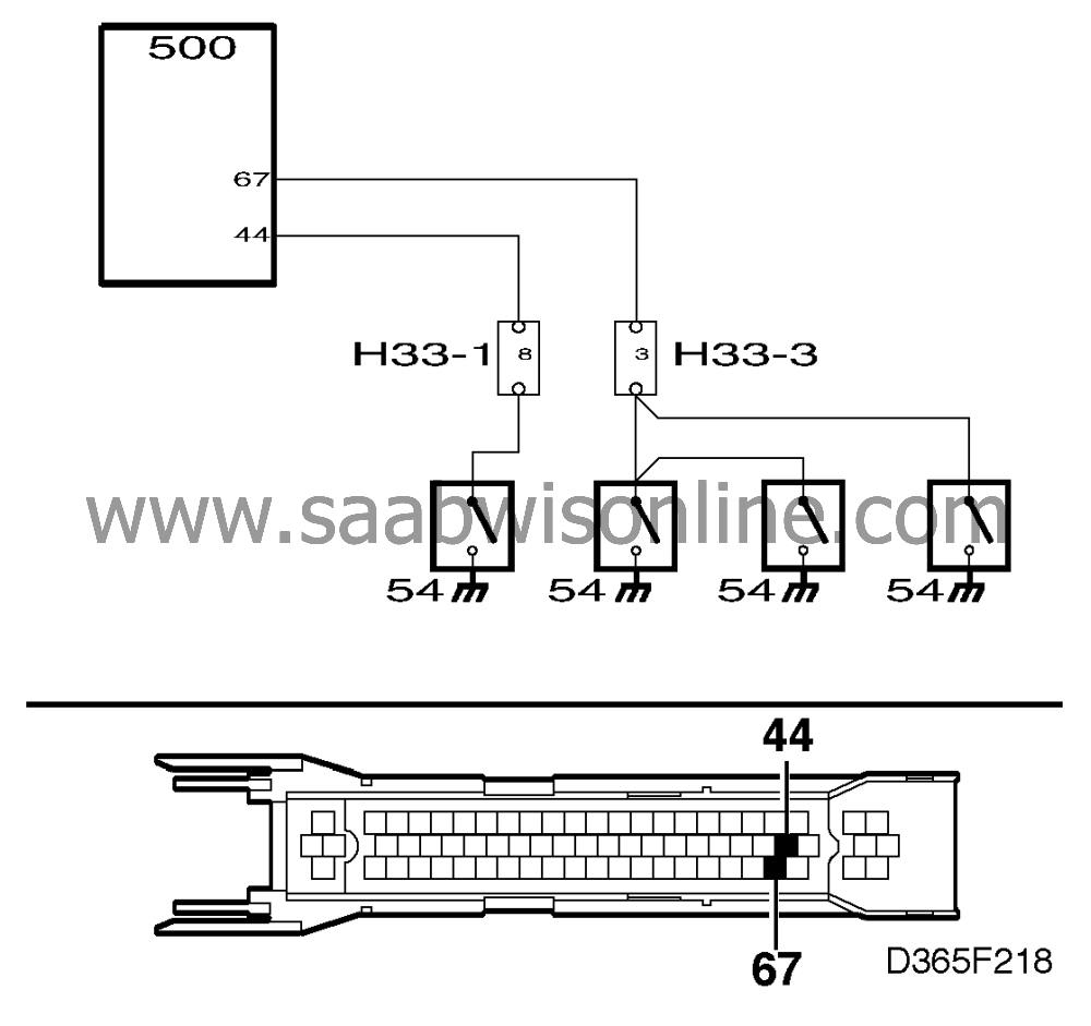
Connect a BOB and check the lead for continuity/shorting as follows:

|
|
| • |
between ICE module connector pin 44 and the switch
in the driver's door.
|
| • |
between ICE module connector pin 67 and the three passenger door switches.
"Door open" indicator lamp |
| 5. |
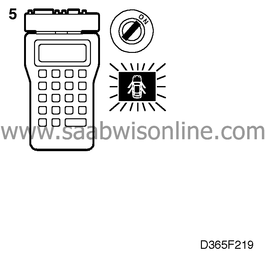
Select "ACT. INSTR. FUNCT" from the scan tool menu and then "DOOR INDIC.
LAMP". The lamp in the main instrument display panel should light up when the ignition switch
is "ON".
|
|
| 7. |
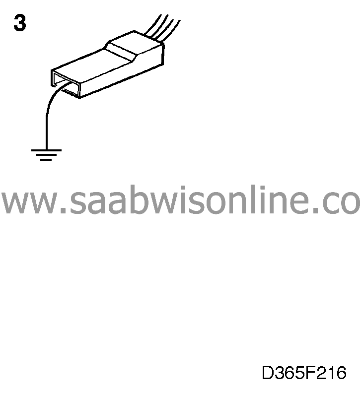
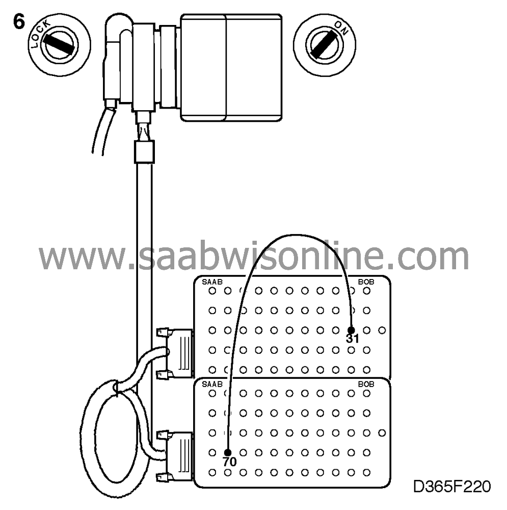
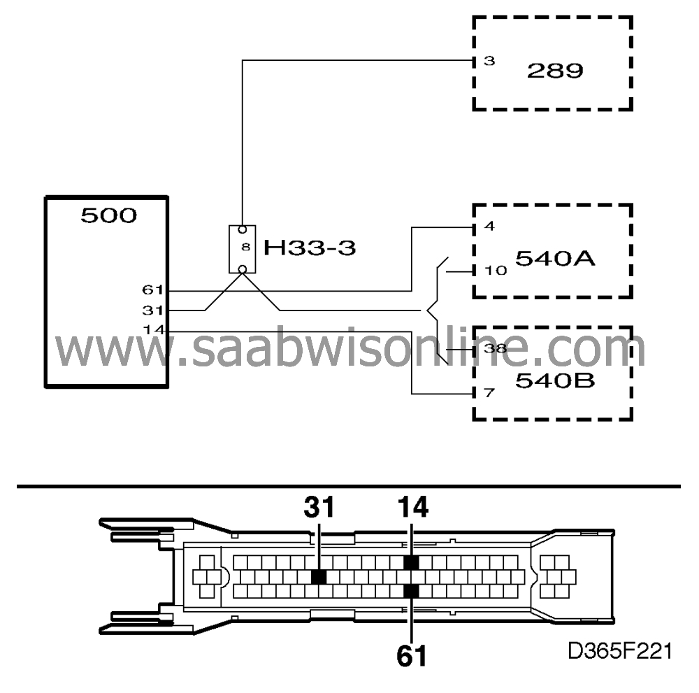
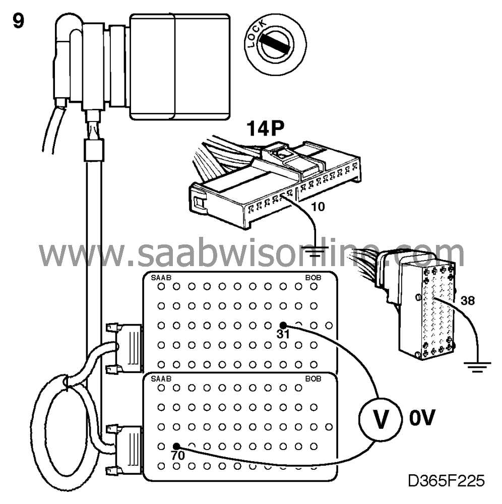
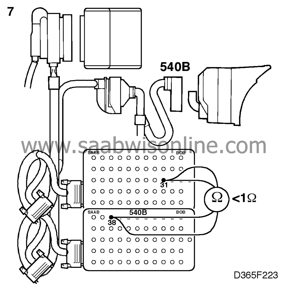
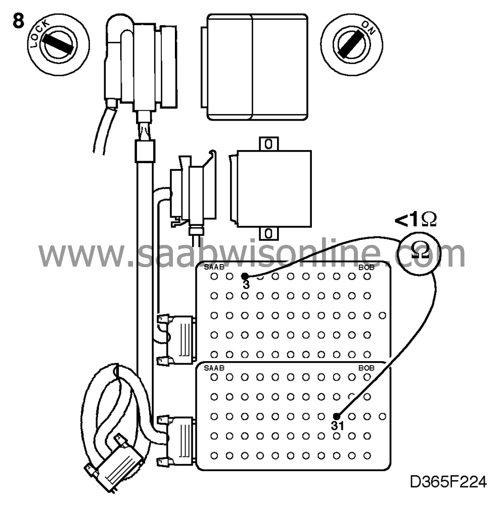
If it is not, check the lead for continuity/shorting as follows:

|
|
| • |
between pin 31 of the ICE module connector and pin
10 of the main instrument display panel connector (main instrument display panel 1)
|
| • |
between pin 31 of the ICE module connector and pin 38 of the main instrument
display panel connector (main instrument display panel 2)
|
| 8. |
If the car is equipped with an anti-theft alarm, also check the lead
between pin 31 of the ICE module connector and the anti-theft alarm control module for
continuity/shorting.
|
|

