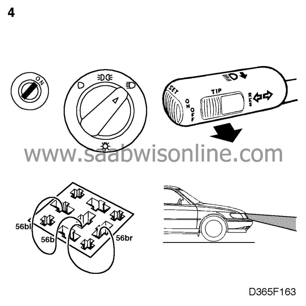
Main and dipped beams
| Main and dipped beams |
| 1. |
Check that fuses 6-9 in the front
main fuse box in the engine bay are intact and live. If they are not, proceed to point 4.
|
|
| 2. |
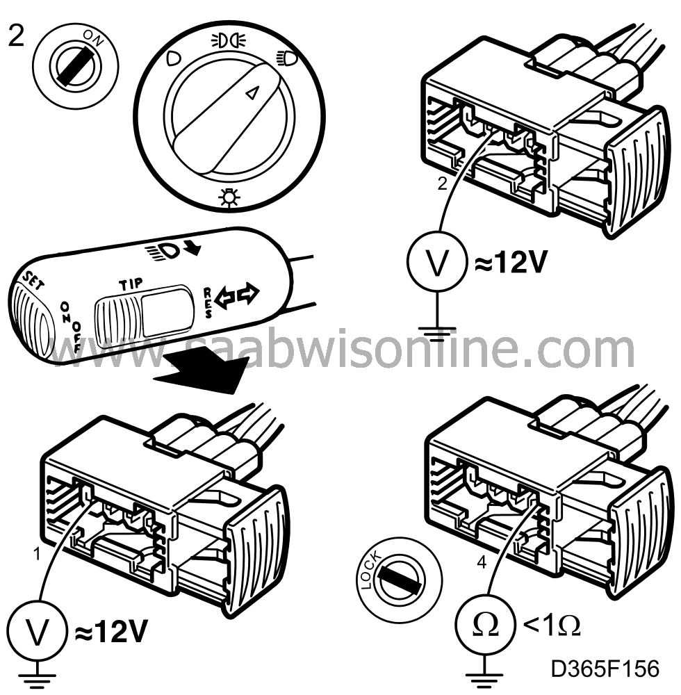
Check that the bulbs are OK and that they are supplied with 12 V, as follows:
|
|
| • |
between connector pin 2 and a good grounding point
for dipped beam.
|
| • |
between connector pin 1 and a good grounding point for main beam.
|
| • |
Also check that the resistance across connector pin 4 and a good grounding
point is < 1 ohm.
|
| 3. |
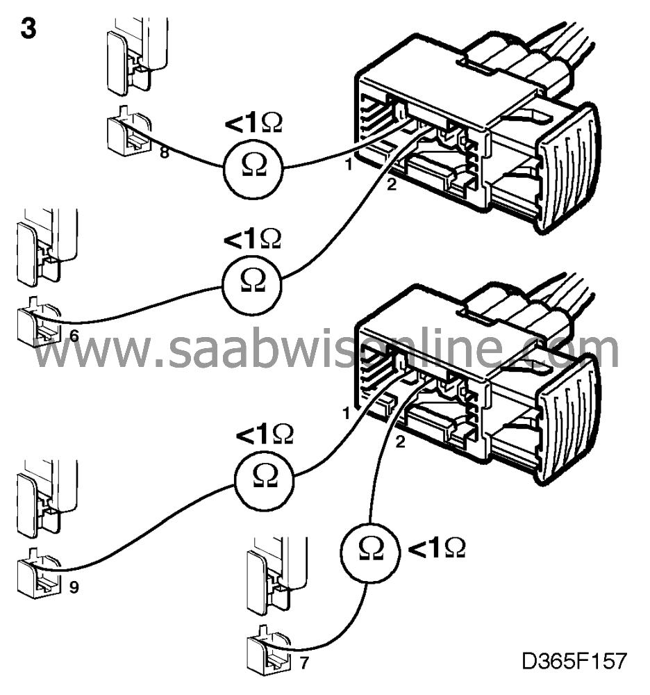
If the power supply does not reach pin 1 or pin 2, check the wiring between the
fuse and the lamp for continuity/shorting.
|
|
| 4. |
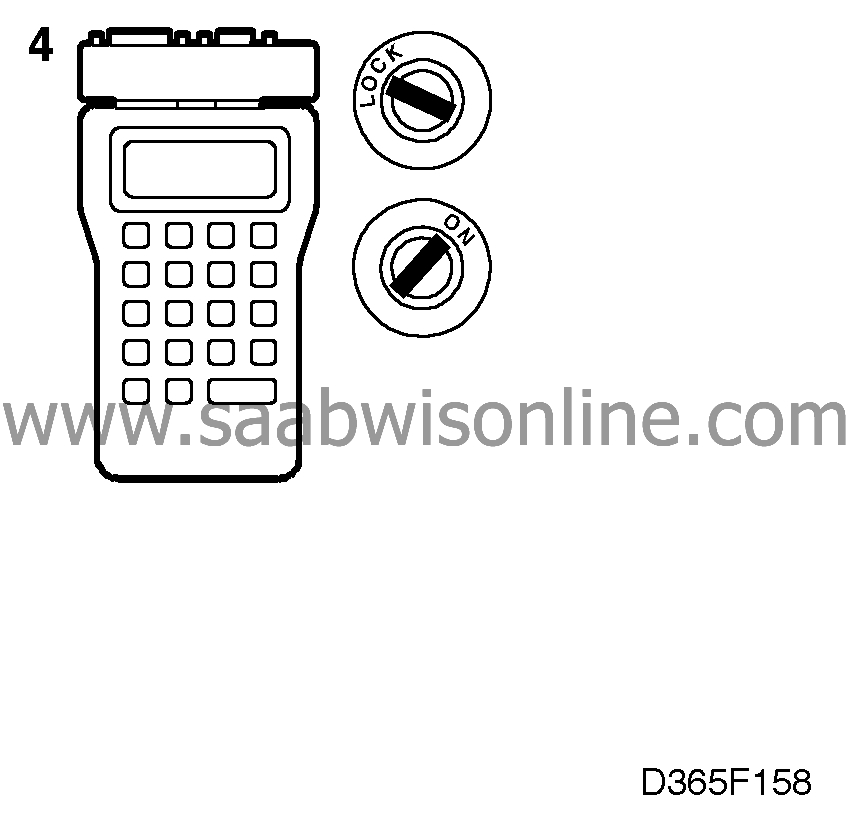
Plug in the scan tool and select "READ FAULT CODES" from the menu. If any
trouble codes are present, continue on
 .
.
|
|
| Filament monitor |
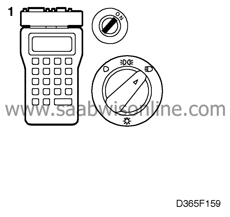
| 1. |
Select "ACTIVATE RELAY" and
then "HEADLAMPS" or "HIGH BEAM". The lights should be activated when the ignition switch
is "ON".
If this is the case, proceed to point 1 on the next page. |
|
| 2. |
If it is not, unplug the filament monitor and check that 12 V is supplied to the
relay holder's:
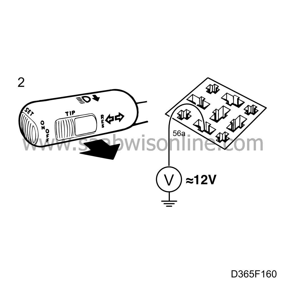
|
|
| • |
pin 56A for main beam
|
| • |
pin 56B for dipped beam
If no power supply is present, proceed to point 1 on the next page. |
| 3. |
Also check the grounding by taking a resistance reading across pin 31 and a
good grounding point. Resistansen ska vara < 1 Ohm.
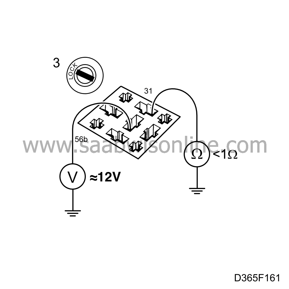
|
|
| 4. |
If the power supply as in point 2 is OK, connect jumper leads to check the
filament monitor.

|
|
| • |
Connect a jumper lead between 56B and 56BL (left-hand) and also between 56B
and 56BR (right-hand) to check the dipped beam.
If the main and dipped beams now work OK, the fault is in the filament monitor. Change the filament monitor. |
| Dipped beam |
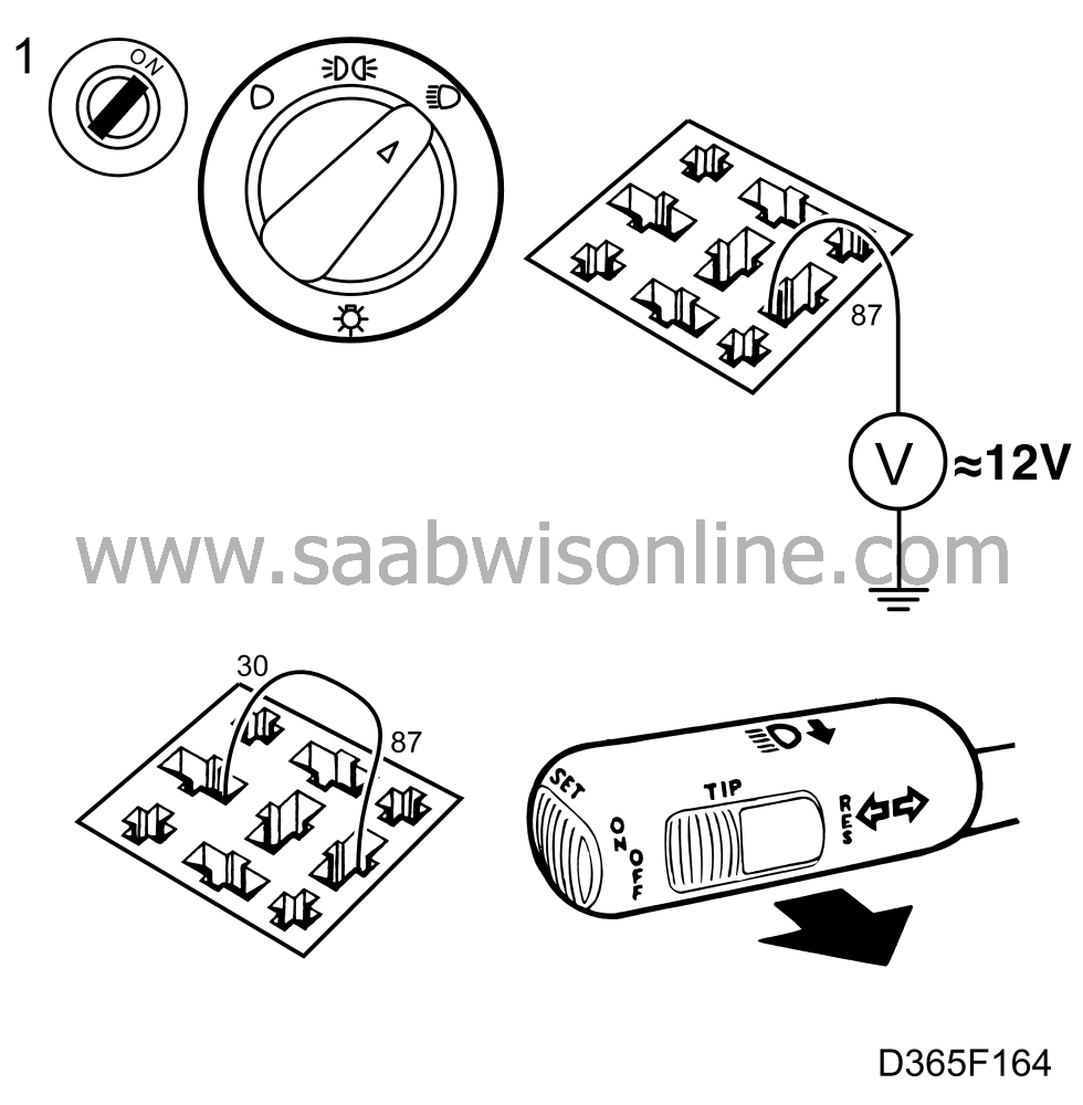
| 1. |
Check whether 12 V is present
on headlamp relay connector pin 87 in the relay holder.
If 12 V is present, connect a jumper lead between connector pins 30 and 87 and activate the headlamps. If the headlamps work, the fault is in the relay. Change the relay. |
|
| 2. |
If they do not work, check whether 12 V is present on pin 30 of the main and
dipped beam relay connector when the headlamps are activated.
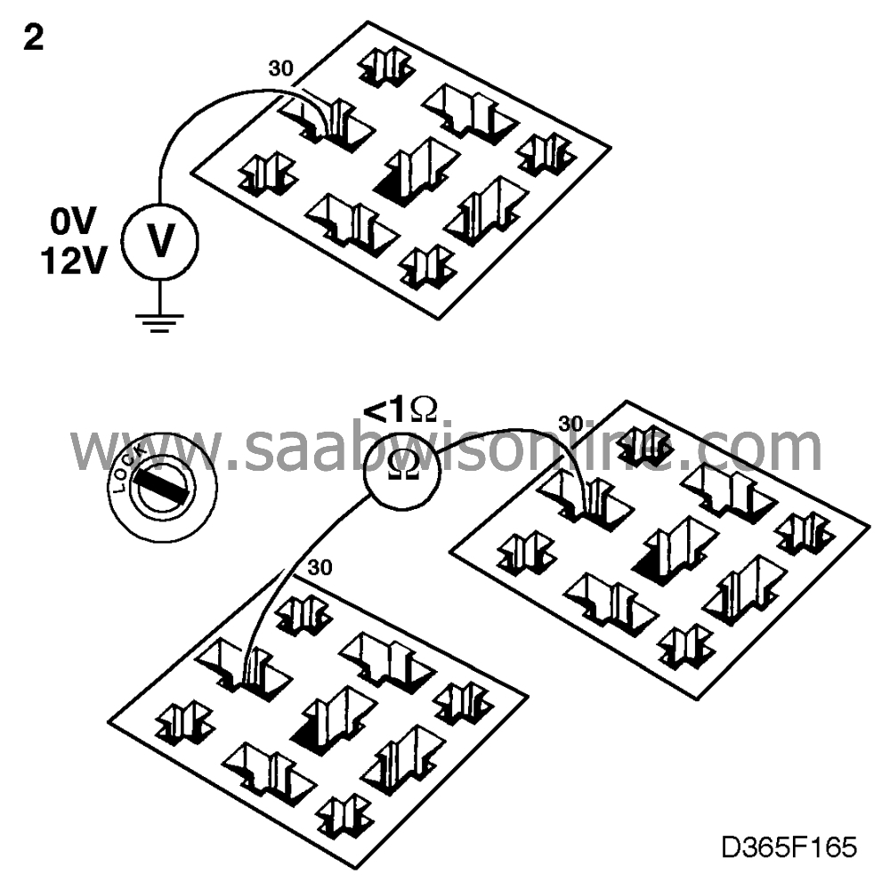
If it is not, check the wiring between the relays for continuity/shorting. |
|
| 3. |
Check whether 12 V is present on pin 56B of the filament monitor connector
when the headlamps are activated.

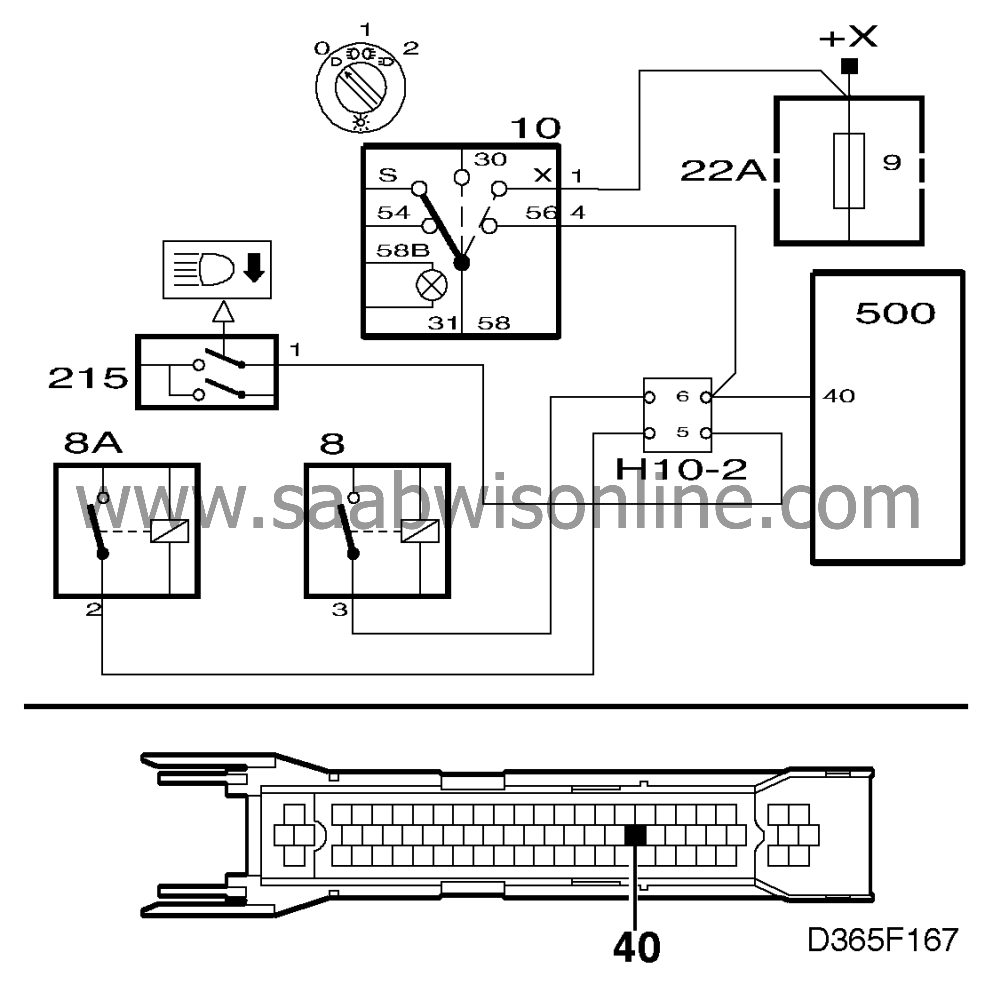
If it is not, check the wiring between pin 87A of the main and dipped beam relay connector and pin 56B of the filament monitor connector for continuity/shorting. |
|
| Main beam |
| 1. |
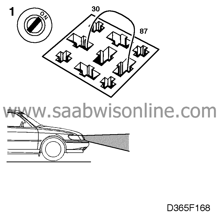
Connect a jumper lead between
pins 30 and 87 of the dipswitch relay connector and check whether the headlamps light up on
main beam.
If the headlamps work, the fault is in the relay. Change the relay. |
|
| 2. |
If they do not, check whether 12 V is present on pin 56A of the filament monitor
connector when the headlamps are activated on main beam. (The jumper lead should still be
connected as in point 1 above.)

|
|
| 3. |
If 12 V is not present, check the wiring between pin 87 of the dipswitch relay
connector and pin 56A of the filament monitor connector for continuity/shorting.


|
|
| Dipswitch |
| 1. |
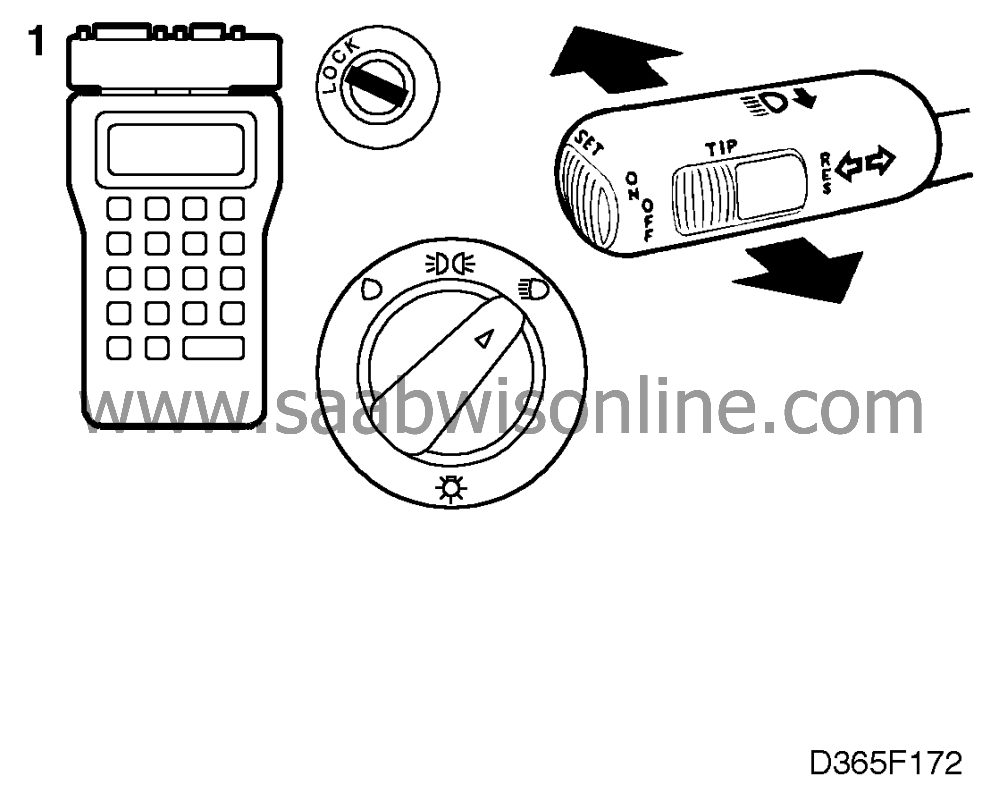
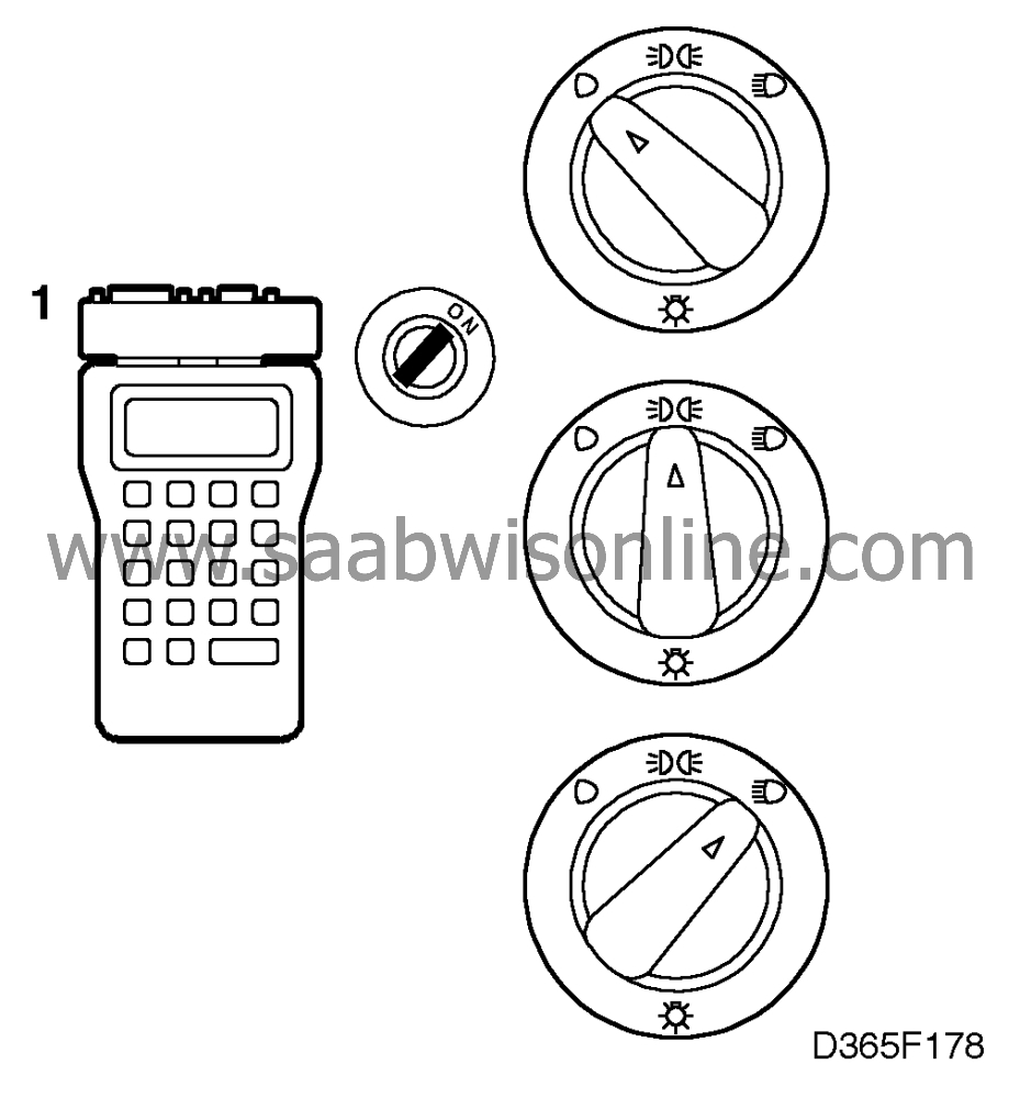
Check the dipswitch by
selecting "READ SWITCHES" from the menu and then "DIPSWITCH".
Alternate between dipped and main beam. The scan tool display should read "HIGH BEAM" (the dipswitch must be held in continuously for the scan tool to display "HIGH BEAM") or "LOW BEAM". |
|
| 2. |
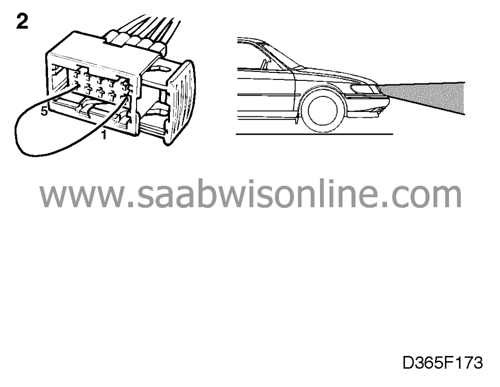
If it does not, check the dipswitch by connecting a jumper lead between pins 1
and 5 of the headlamp flasher connector. If the headlamps are activated on main beam, the
fault is in the dipswitch. Change the dipswitch.
|
|
| 3. |
Check whether the headlamps work by connecting a jumper lead between pins 5
and 6 of the dipswitch connector.

(We check the headlamps in Limp-Home mode.) |
|
| 4. |
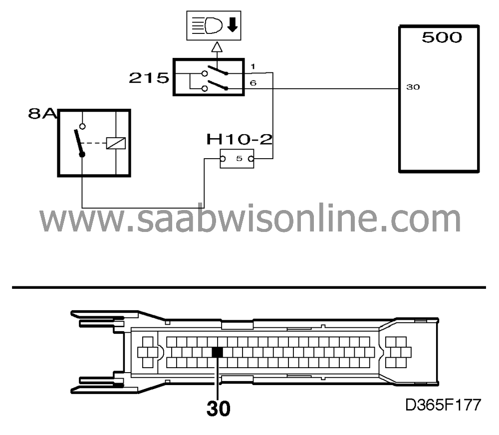
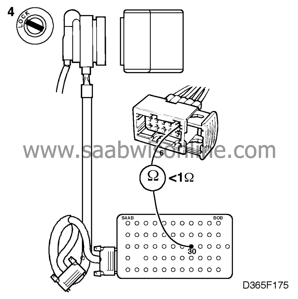
Connect a BOB and check the lead between ICE module pin 30 and dipswitch
connector pin 6 for continuity/shorting.
|
|
| 5. |
If the headlamp flasher does not work in point 2, check the lead between
dipswitch connector pin 1 and filament monitor connector pin 56A.

|
|
| 6. |
If the fault persists after the above checks have been carried out, continue fault
diagnosis as described on
 .
.
|
|
| Lights switch |
| 1. |
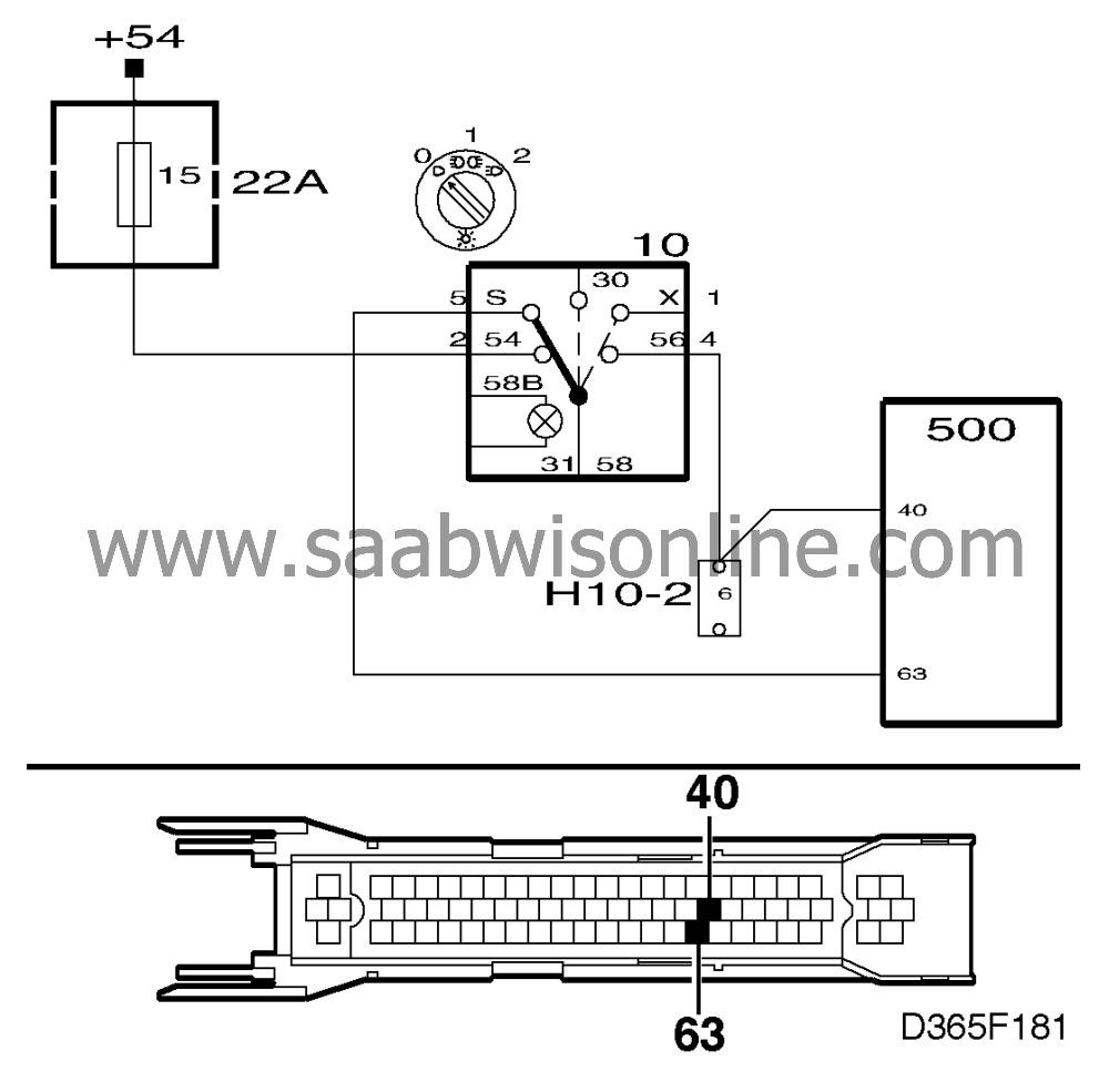
Check the lights switch by
selecting "READ SWITCHES" from the menu and then "LIGHTS SWITCH".
Turn the lights switch from position 0 to position 2. The display should then show: "POS. 0" "POS. 1" "POS. 2" |
|
| 2. |
If it does not, check the lights switch by measuring the resistance:
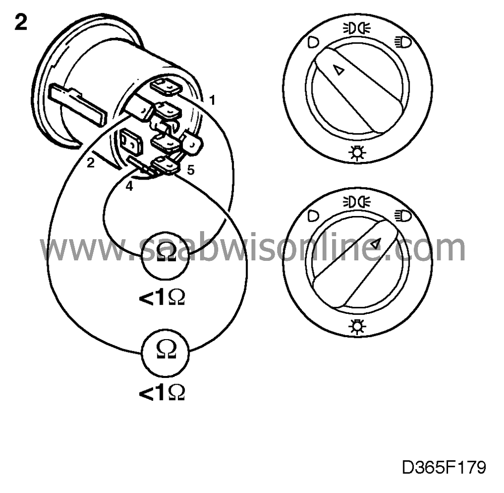
|
|
| • |
across pins 2 and 5 with the lights switch in position 0.
|
| • |
across pins 1 and 4 with the lights switch in position 2.
If the instrument shows a resistance of < 1 ohm, the lights switch is OK. |
| 3. |
Connect a BOB and check the lead for continuity/shorting as follows:

|
|
| • |
between pin 40 of the ICE module connector and pin
4 of the lights switch connector.
|
| • |
between pin 63 of the ICE module connector and pin 5 of the lights switch
connector.
|


