General relay fault diagnosis on generation of aDTC
|
|
General relay fault diagnosis on generation of a
DTC
|
This fault diagnosis section will be helpful when diagnosing faults such as an
open circuit, ground fault and short circuit in the relay itself.
|
1.
|
First check that the relay fuse (if
there is one, see system wiring diagram) is intact and live.
|
|
2.
|
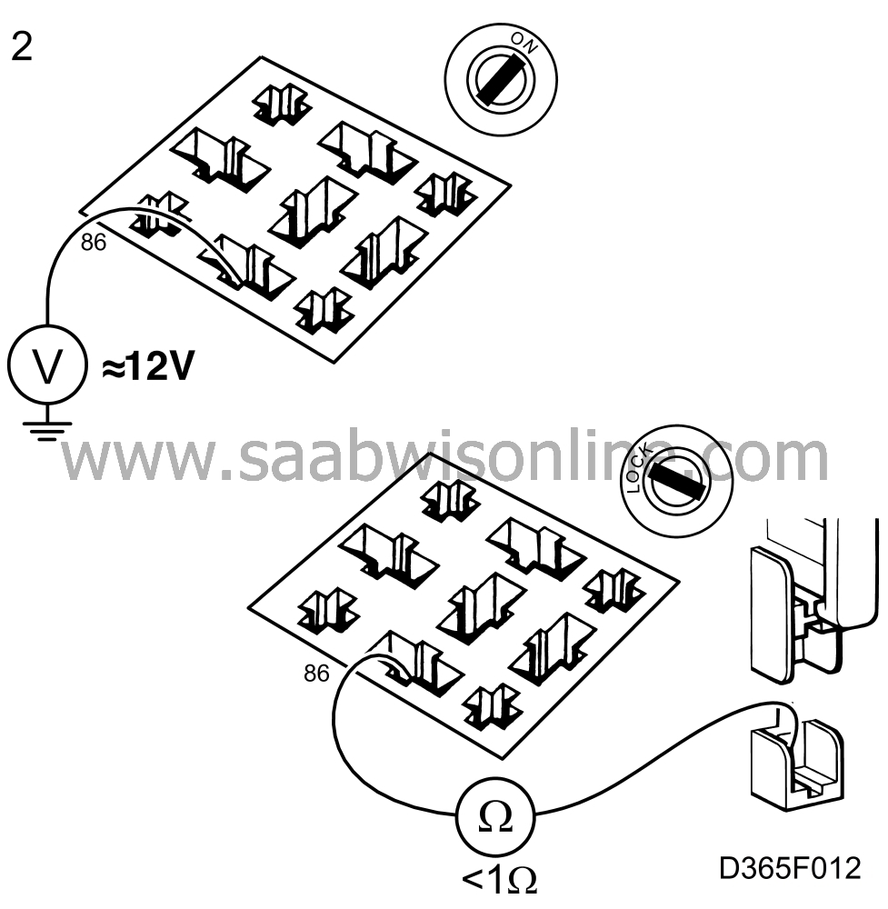
With the ignition switch in the Drive position, check that power is supplied to the
operating coil via relay pin 86. If no power supply is present, check the wiring between fuse
and relay for continuity/shorting.

|
|
3.
|
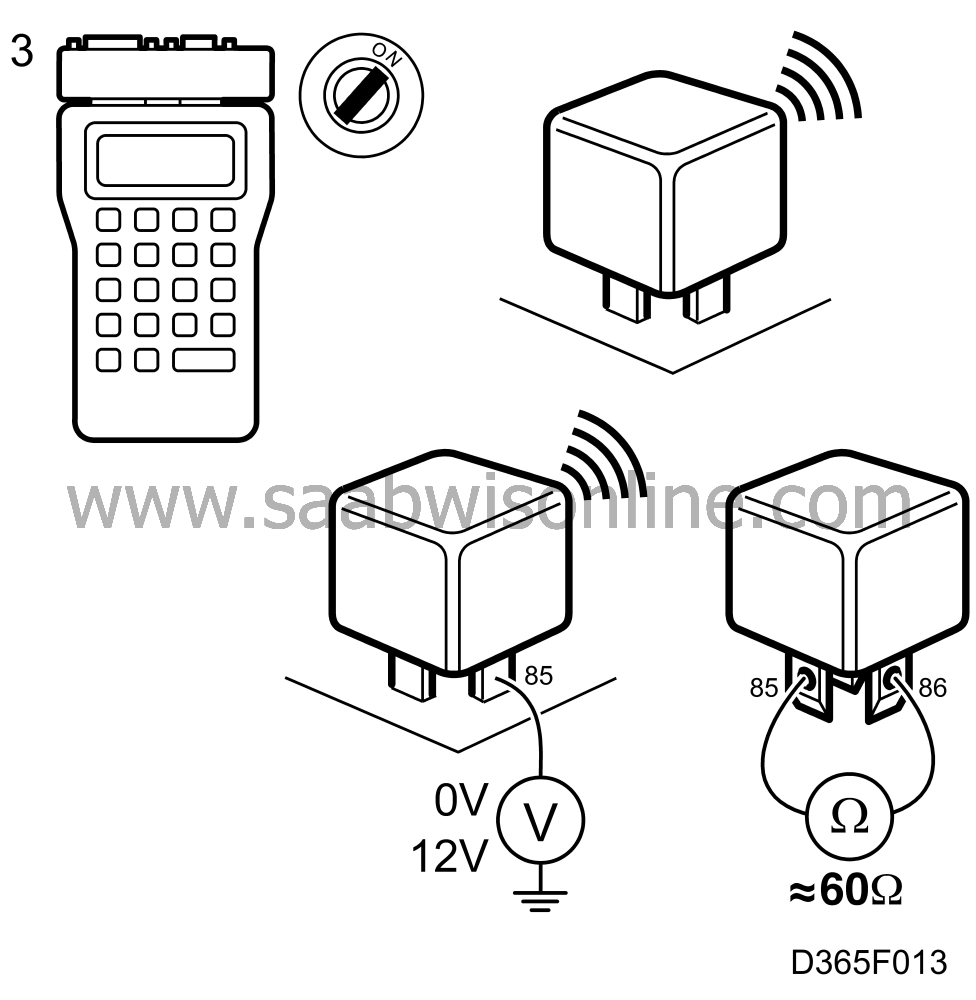
Plug in the scan tool and select "ACTIVATE RELAY" from the menu. Then select
the next activation command, which could be "RADIATOR FAN LOW" if you are checking the
low speed radiator fan relay. Take a voltmeter reading on relay pin 85. The relay should
remain in place but slightly raised.
Start from point 3 again and check the voltmeter readings as follows:
Relay activated - 0 V
Relay not activated - 12 V
If the voltmeter readings are not OK, remove the relay and check that the resistance of
the relay coil across pins 85 and 86 is between 50 and 100 ohms.
If the resistance is not OK, change the relay.

|
|
4.
|
If the resistance is OK, check that the relay pins are securely located and that
the relay is pressed firmly into position on the relay holder.
|
|
5.
|
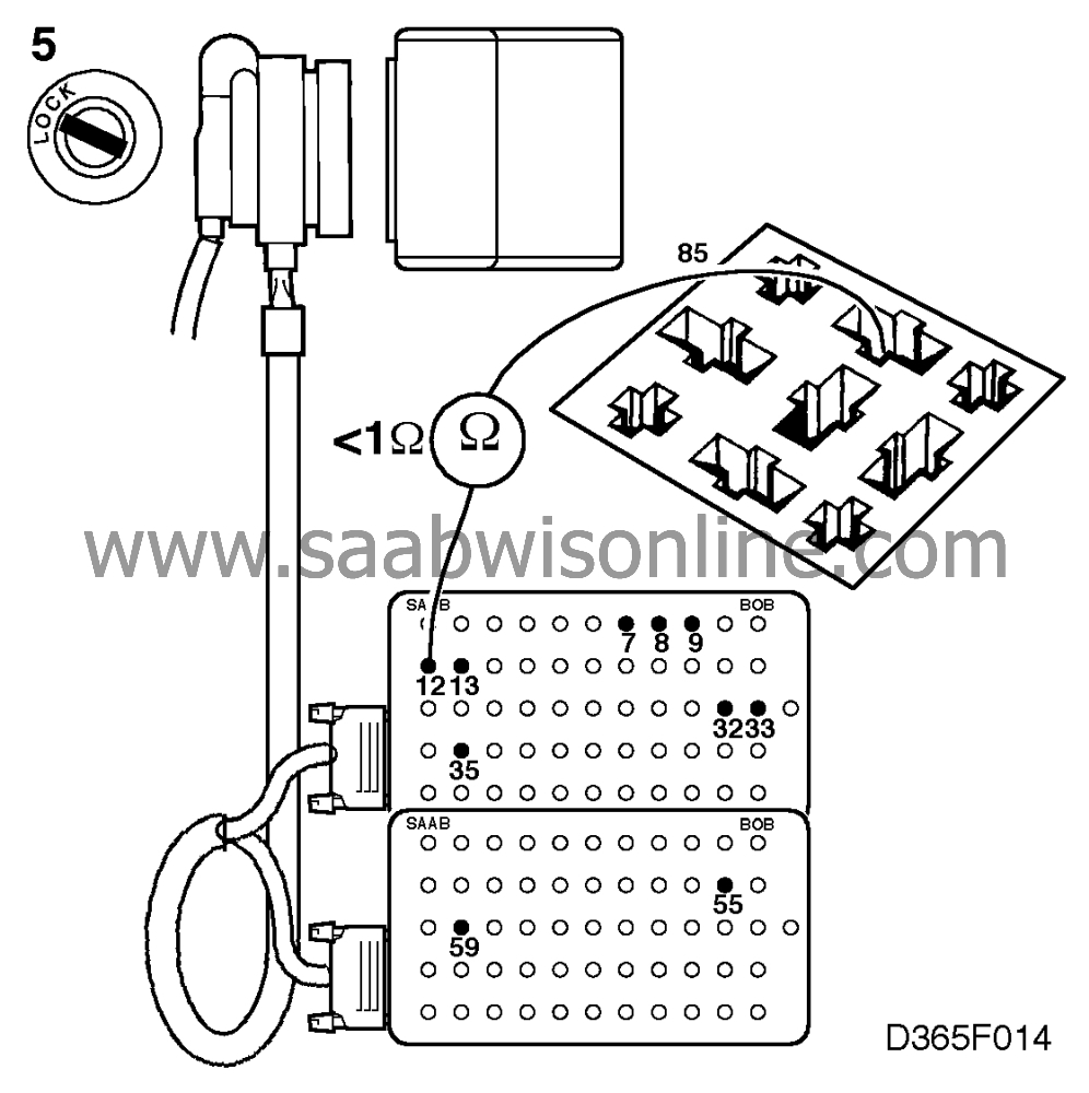
With the ignition switched off, connect a BOB to the ICE wiring (control module
disconnected). Check the lead between the ICE control module connector and pin 85 of the
relay holder for continuity/shorting to ground. Rectify or change any faulty wiring or
connector.

|


