Correcting a Customer Complaint of Hard Brake Pedal Effort When Starting a Cold Engine
|
SERVICE INFORMATION
|
|
Bulletin Nbr:
|
541-9029
|
|
Date:
...........
|
APRIL 1996
|
|
Market:
|
US
|
|
|
Correcting a Customer Complaint of Hard Brake Pedal Effort When Starting a Cold Engine
|
This bulletins contains a repair procedure for installing a new vacuum pump kit (see Figure) to address a customer complaint of hard brake pedal effort when starting a cold engine.
1994 900 models with 2.5 liter V6 engine and without air pump
1994- 900 models with 2.3 liter 4-cylinder engine with air pump
1995- 900 models with 2.5 liter V6 engine with air pump
Kit, all cars: 47 78 411
Contains the following:
|
-
|
Connector (contact housing)(2): 91 24 157
|
|
-
|
Wiring harness (1): 47 39 678
|
|
-
|
Adaptor harness, vacuum pump (1): 47 39 686
|
|
-
|
Adaptor harness, fog light (1): 47 39 694
|
|
-
|
Relay (micro) (2): 42 24 192
|
|
-
|
Fuse, 10A (1): 79 74 637
|
|
-
|
Cable tie (12): 79 71 864
|
|
-
|
Pressure (vacuum) switch (1): 46 92 802
|
|
-
|
Vacuum pump (1): 46 46 220
|
|
-
|
Hose for vacuum pump (2): 46 46 923
|
|
-
|
Hose clamp (4): 79 74 009
|
|
-
|
Rubber bushing (4): 42 35 768
|
|
-
|
Nylock nut(3): 79 74 298
|
|
-
|
Cable tie with pin (arrow head)(4): 85 52 663
|
|
-
|
Cable tie with clip (4): 89 43 177
|
|
-
|
Cable tie, large (2): 79 71 800
|
|
-
|
Cable tie (1): 79 84 750
|
|
-
|
Check (non-return) valve (1): 43 73 288
|
|
-
|
Check (non-return) valve with T-connection (1): 46 47 624
|
|
-
|
T-connection (1): 46 47 632
|
|
-
|
Hose for pressure (vacuum) switch (1): 91 35 757
|
|
-
|
Bracket for vacuum pump (1): 46 48 663
|
|
Note
|
|
After installing the vacuum pump kit on a 900 model with 2.3 liter 4-cylinder engine, you will have extra parts: (2) hose clamps, (1) check valve, (1) check valve with T-connection, and (1) T-connection.
|
Support (bracket), secondary air injection pump, 1994 V6 cars only (1): 42 29 423 (see note, below)
|
Note
|
|
1994 models without air pump require installation of a secondary air injection pump bracket before installing the brake vacuum pump kit. The secondary air injection pump bracket must be ordered separately. This part is not included in the vacuum pump kit.
|
|
Part number 42 29 423 will be used until the supply is exhausted. it will then be superseded by P/N 47 79 104. When the supersession occurs, you will also receive a bushing that provides correct spacing for the new bracket.
|
|
Vacuum pipe (hose), 4-cylinder cars only (pre-formed, includes check valves and fittings)(1): 46 46 238
|
Check that the kit contains all parts (refer to the parts list).
|
1.
|
Put the car on a lift.
|
|
2.
|
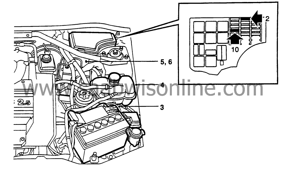
Remove fuse no. 2 (fog light) and no. 10 (headlight wipers). See items 2 and 10, Figure above.
|
|
3.
|
Remove the battery (item 3, Figure above).
|
|
4.
|
Move the expansion tank (item 4, Figure above) and for 4-cylinder cars only, remove the air plenum. Lift the inlet cover for access.
|
|
5.
|
Cut the three cable ties (item 5, Figure above) to release the front harness and lift the relay/fuse panel out of the fuse box.
|
|
6.
|
Remove the box outlet seal from the cable harness (item 6, Figure above).
|
|
7.
|
Remove the left front wheel, the left-hand cover plate, and the parking lamp from behind the spoiler.
|
|
8.
|
Remove the left front parking lamp for easier access when routing wiring and hoses. Some technicians might find it helpful to remove the left front headlamp, also.
|
|
9.
|
Loosen and pull back the front part of the left fender liner and temporarily hook it behind the brake caliper.
|
|
10.
|
Remove the bottom of the spoiler (left side lower cover).
|
|
11.
|
Cars with auxiliary air pump: remove the air pump assembly.
|

|
1.
|
Fit the vacuum pump including the rubber bushing to the supplementary bracket (46 48 663).
|
|
2.
|
Install the rubber bushings (item 2, Figure above) on the right side of the supplementary bracket before marking the hole location in the next step. Otherwise, the hole in step 3 will be off by the thickness of the bushings.
|
|
3.
|
Hold the supplementary bracket against the rear side of the air pump bracket and mark the lower left hole. Drill a 17/64” (6.5mm) hole in the air pump bracket and apply anti-corrosive primer. See item 3, Figure above.
|
|
4.
|
Remove the plastic cover nuts and the washer fluid reservoir securing screw. Insert the bracket (46 48 663) between the washer fluid reservoir and the body flange.
|
|
5.
|
Using the two M6 locknuts, secure the pump and bracket assembly to the body.
|
|
6.
|
Resecure the washer fluid reservoir using the screw and plastic cover nuts.
|
|
7.
|
Fit the four rubber bushings (42 35 768) to the bracket (46 48 663).
|
|
8.
|
Fit the two assemblies together.
|
|
9.
|
Refit the whole assembly into the original location. See Figure above.
|
|
10.
|
Reconnect the air pump harness. Use two cable ties (79 71 880) to secure the wires to the bracket.
|
|
11.
|
Fit the hose to the vacuum pump and secure with a hose clamp (79 74 009). Mount the vacuum pump on its bracket.
|
|
12.
|
Route the hose in front of the engine mount, into the engine compartment, and on towards the firewall along the power steering hoses up to the ABS control module. Adjust the hose length as necessary at the connection to the check valve.
|
|
13.
|
Plug the wiring harness’ white connector to the vacuum pump. See Figure on page 5 and refer to the caution below it.
|
|
14.
|
Replace the fender liner, the left-hand cover plate, the parking lamp, and the left front wheel.
|
|
Note
|
|
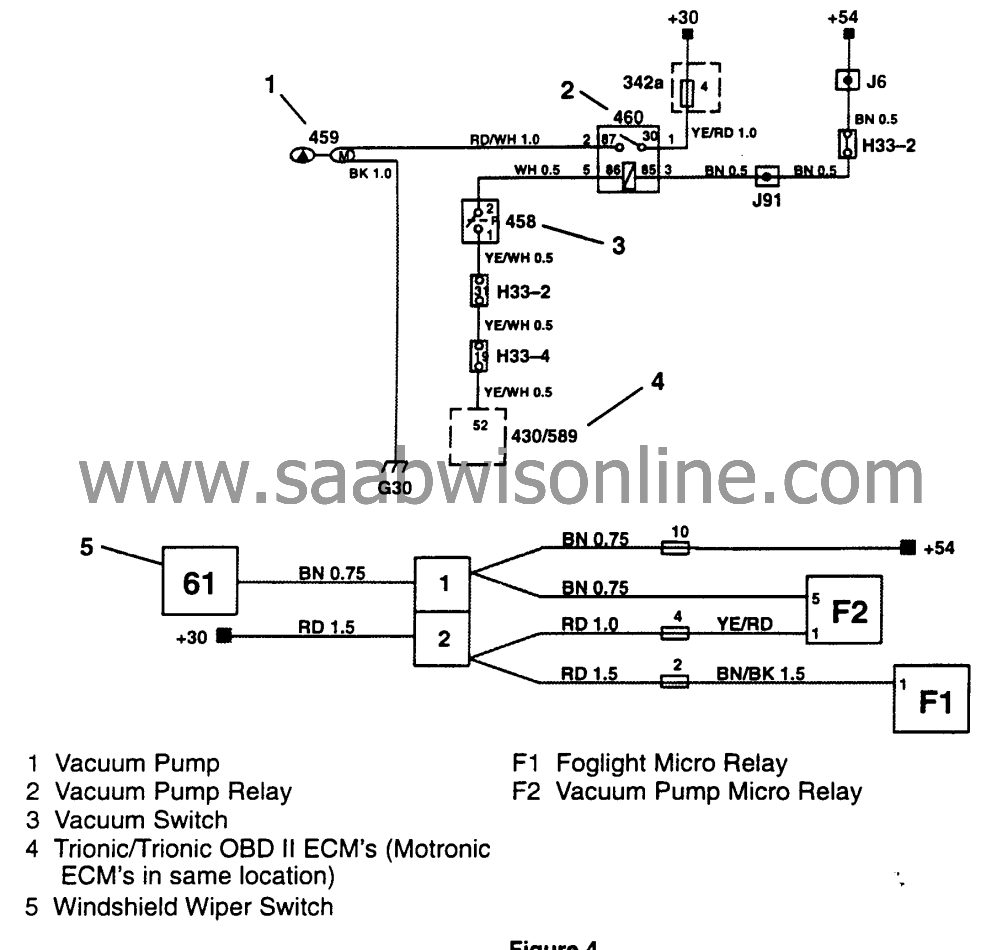
The F2 and F1 designations in the figure above refer to the relay location stamped on the bottom of the fuse box cover located under the hood.
|
|
1.
|
Connections in the relay/fuse box:
M1994-95: remove relay holder position F (fog light; will be replaced by two micro relay holders 44 09 934).
Pos F1 = fog light relay
Pos F2 = vacuum pump relay
Fitting wiring harnesses continued:
|
Note
|
|
The fog light relay will either be a standard size relay (approximately 1x1x1 in.) or a half-size relay. For a standard size relay, follow the instructions in step 2. For a half-size relay, skip to the instructions in step 3. For these cars, some of the wiring components supplied in the kits will not be used.
|
|
|
2.
|
Connections for replacing the standard fog light relay; use adapter harness (47 39 694) with relay holder (44 09 934).
|
|
|
2.a.
|
When fitting wires as indicated in the following steps, be sure to route all of the wires on the bottom side of the relay panel. This will allow you to just raise the micro fog light relay socket into place when this work is completed.
|
|
|
2.b.
|
Remove the Brown/Black 1.5 wire from position 1. Refit this wire in the new micro relay holder position 1.
|
|
|
2.c.
|
Remove the two Red/Black 1.0 wires from position 2. Refit these wires into position 2 (micro relay holder).
|
|
|
2.d.
|
Remove the Brown/Black 0.5 wire from position 4. Refit this wire in contact housing (91 24 157) position 2.
|
|
|
2.e.
|
Remove the Yellow/Red 0.5 wire from position 5. Refit this wire in contact housing (91 24 157) position 1.
|
|
|
2.f.
|
Connect the micro relay holder ‘’fog light” with the contact housing (91 24 157).
|
|
|
2.g.
|
Fit the pre-wired relay holder (44 09 934) into position F1 and make sure that it is properly secured.
|
|
3.
|
Connections for the half-size vacuum pump relay and fuse; use adapter harness 47 39 686. A micro relay is factory-fitted in position 1.
|
|
|
3.a.
|
Fit the micro relay socket into position F2. Make sure it is properly secured.
|
|
|
3.b.
|
Fit the Yellow/Red 1.0 wire to fuse no. 4 (fused side).
|
|
|
3.c.
|
Remove the Red 1.5 wire from fuse no. 2 (fog light) position 1 (unfused side).
|
|
|
3.d.
|
Refit this wire in contact housing (91 24 157) position 2.
|
|
|
3.e.
|
Connect the Red 1.5 wire from the split contact (41 17 560, stamped on the connector) to fuse no. 2 position 1 (unfused side).
|
|
|
3.f.
|
Remove the Brown 0.75 wire from fuse no 10. (headlight wiper) on the unfused side.
|
|
|
3.g.
|
Refit Brown 0.75 wire that came from fuse no. 10 in contact housing (91 24 157) position 1.
|
|
|
3.h.
|
Connect the split contact (41 70 560) Brown 0.75 wire to fuse 10 on the unfused side.
|
|
|
3.i.
|
Fit the Brown 0.5 wire (from the split contact) into the micro relay bracket (vacuum pump relay position 3).
|
|
|
3.j.
|
Connect the Red 1.0 wire (from the split contact) to fuse no. 4 position 1 (unfused side.
|
|
|
3.k.
|
Plug the split contact (41 17 560) into the contact housing (91 24 157).
|
|
Fitting wiring harnesses (cont’d)
|

|
Important
|
|
Reversing the connections for the vacuum pump harness will blow fuse #4 and the pump will not operate. make sure to install the black connector (item 1, Figure above) to the vacuum switch and the white connector the pump (item 2, Figure above).
|
|
|
|
1.
|
Route the vacuum pump harness through the fuse box outlet and fix cable ties to the main harness on both sides of the outlet seal. Refit the relay/fuse bracket in the fuse box.
|
|
2.
|
Route the vacuum switch wires (black connector) with the OE harness along on the firewall to the switch location. Use three cable ties (79 71 864) to secure the harness in place.
|
|
3.
|
Route the vacuum pump wires (white connector) beneath the expansion tank, forward along the OE front harness to the left front turn signal location, and further to the pump bracket location inside the left fender. Secure with three cable ties (79 71 864).
|
|
4.
|
Refit the relay/fuse box and the expansion tank. Install three cable ties (85 52 633) to the front harness.
|
|
5.
|
Fit the two micro relays (42 24 192):
|
|
|
5.a.
|
M94-95: positions F1 and F2 (see Figure above).
|
|
|
5.b.
|
M95-1/2-: position F2; position F1, fog lamps, is already in place
|
|
6.
|
Attach the ground wire to same ground point as the battery negative cable on the inner fender near the maxi fuse box.
|
|
Fitting vacuum pressure switch, 4 cyl.
|
|
1.
|
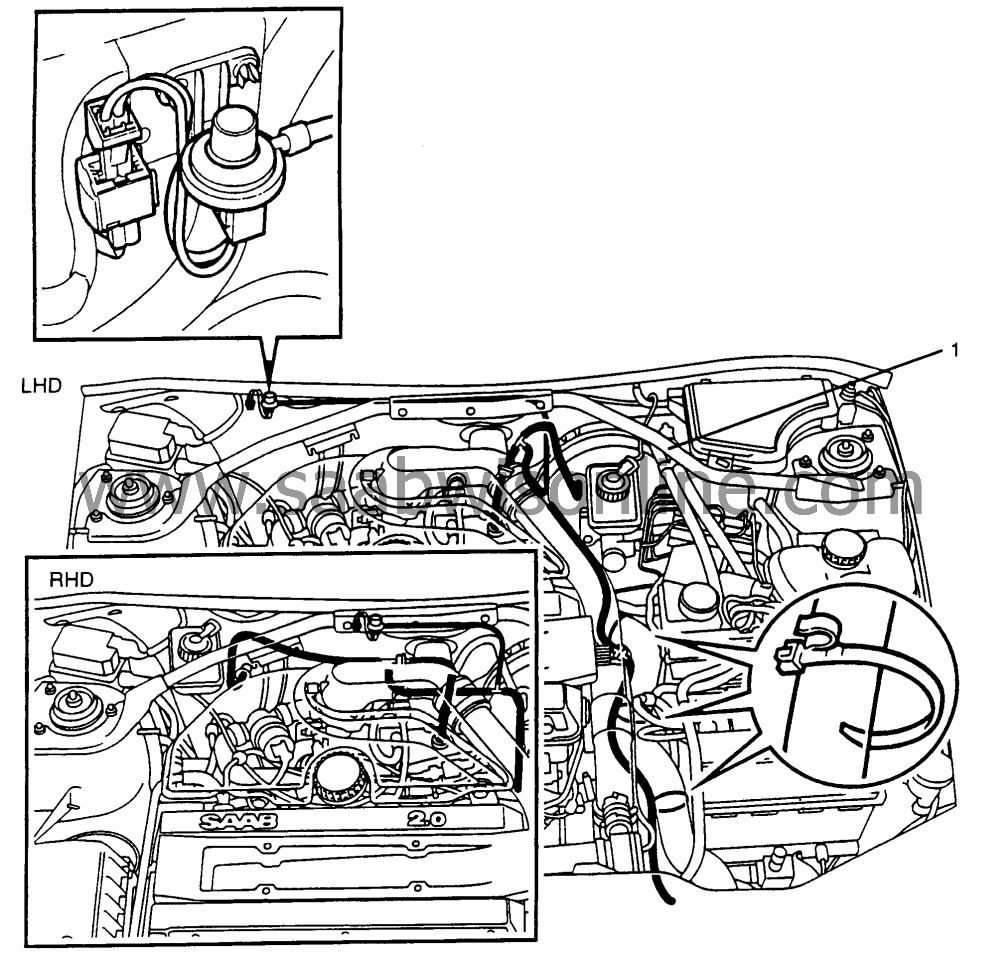
Lift the rubber strip on the bulkhead panel flange and hang it on the pressure switch bracket.
|
|
2.
|
Plug the connector into the pressure switch.
|
|
3.
|
Use a cable tie (79 71 864) to secure the wiring harness to the vacuum pump bracket.
|
|
4.
|
Use a cable tie (79 71 864) to secure the vacuum switch hose to the stabilizer bar (item 1, Figure above).
|
|
Fitting vacuum pressure switch, V6
|

|
1.
|
Remove the firewall seal for access and fit the switch bracket (see Figure above).
|
|
2.
|
Plug the vacuum switch connector into the wire harness and secure the wires to the stabilizer bar (item 1, Figure above) on the firewall using two cable ties (79 71 864).
|
|
Fitting vacuum pump hose, 4 Cyl.
|
|
1.
|
Remove the original vacuum pump hose from between the intake manifold and the power brake servo.
|
|
2.
|
Fit a new pre-molded vacuum pump hose (46 46 238).
|
|
3.
|
Use a hose clamp (79 74 009) to connect the vacuum pump hose to the check valve.
|
|
4.
|
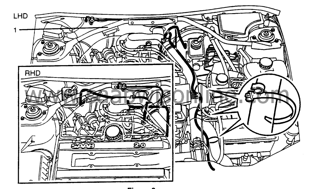
Use a cable tie (89 43 177) to secure the vacuum pump hose to the stabilizer bar (item 1, Figure above).
|
|
5.
|
Use the other three cable ties to secure the hose in the engine compartment (see Figure above).
|
|
6.
|
Connect the 8mm rubber hose from the T-piece (46 47 632) to the vacuum pump pressure switch.
|
|
1.
|
Use a hose clamp to connect the rubber vacuum hose to the vacuum pump.
|
|
2.
|
Route the rubber hose from the wheel well and into the engine compartment near the battery shelf. Continue to route the hose between the engine and the ABS unit.
|
|
3.
|
Remove the OE vacuum pipes that connect the inlet manifold to the power brake servo.
|
|
4.
|
Remove the OE connections (inlet manifold and power brake) from the OE vacuum pipe. Cut the formed plastic line carefully to avoid damaging the barbed connections.
|
|
5.
|
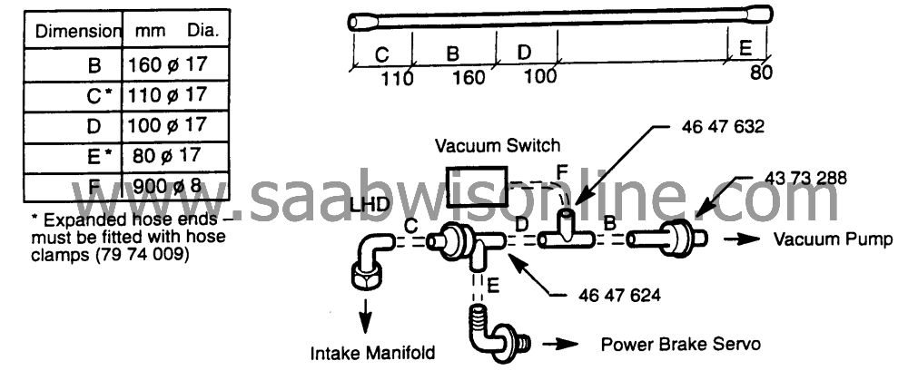
Referring to the length and locations in Figure above, mark and cut the vacuum hose (46 46 923).
|
|
6.
|
Apply a thin layer of acid-free petroleum jelly on all connections.
|
|
7.
|
Fit valves and connections as shown.
|
|
8.
|
Fit the new vacuum hose assembly between the inlet manifold and the power brake servo.
|
|
9.
|
Use the hose clamp to secure the vacuum pump hose to the one-way check valve. See Figure below.

|
|
10.
|
Connect the 8mm hose from the T-connection to the vacuum switch.
|
|
11.
|
Use a cable tie (89 43 177) to secure the vacuum hose to the stabilizer bar (located above the ABS unit).
|
|
12.
|
Connect the 8mm hose from the T-connection to the vacuum switch.
|
|
13.
|
Use a cable tie (89 43 177) to secure the vacuum hose to the stabilizer bar (located above the ABS unit).
|
|
Refitting and function test, V6 and 4 cyl.
|

|
1.
|
Refit all parts except the fuse box cover.
|
|
2.
|
Connect the battery cables.
|
|
3.
|
Refit fuse no. 4 (10A) (vacuum pump).
Refit fuse no 2 915A) (fog light)
Refit fuse no. 10 (7.5A) (headlight wipers)
|
|
4.
|
Without starting the engine, turn the key to the ignition ‘’ON” position. Check that relay F2 activates and that the vacuum pump functions (see note below).
|
Note
|
|
Place your finger on relay F2 during the test if the operation is difficult to hear due to background noise. Due to its capacity, the vacuum pump will only operate for a few seconds. If you pump the brake pedal several times with the engine off and key in the ignition on position, the pump will cycle again.
|
|
|
5.
|
Check that the headlight wipers and the fog light function correctly.
|
|
6.
|
Refit the fuse box cover.
|
|
Circuit diagram, vacuum pump, Saab 900
|


