Check/replacement of seat backrest
|
MODIFICATION INSTRUCTION
|
|
Bulletin Nbr:
|
852-1575
|
|
Date:
...........
|
DECEMBER 1994
|
|
Market:
|
ALL
|
|
|
Check/replacement of seat backrest
|
Saab 900 in the following VIN interval: R2027373 - R2047546 and S2000001 - S2009903
Saab 900 Convertible in the following VIN interval: S7000001 - S7002837, S7010001 - S7013081
It has become apparent that the frame for the front seat backrest on a number of cars within the stated VIN intervals has been supplied in an inferior version that does not meet with Saab's demands on lifespan due to an oversight from the subcontractor.
|
•
|
Backrest frames as follows:
Manual seats
46 28 053 - convertible and 3D left-hand side
46 28 061 - convertible and 3D right-hand side
46 28 020 - 5D left-hand side
46 28 038 - 5D right-hand side
Electrically adjustable seats
43 78 899 - convertible and 3D both sides
42 13 914 - 5D both sides
|
|
•
|
84 71 062, fitting kit upholstery staples
For three door cars and convertible, the following materials are also needed:
|
|
•
|
82 35 178 blind rivets 2 pcs driver's seat, 4 pcs passenger seat
|
|
•
|
46 30 646 catch washers
|
|
•
|
43 79 137 grommet 1 pc driver's seat, 2 pcs passenger seat
|
|
Marking the modification identity plate
|
When the check/measure has been carried out, the modification identity plate should be marked in box C2. Punch in the number "7" if the check/measure has been carried out by the importer and the number "8" if it has been carried out by a dealer.
Each backrest frame should be welded with two weld runs on each side i.e. four weld runs per seat.
Check that the backrest frame is welded with two weld runs on each side as illustrated according to the method below.
|
1.
|
Move the seat to the front end position.

|
|
2.
|
Driver's seat and electrically adjustable seats. Raise the seat as far as possible.
|
|
3.
|
Lift up the backrest upholstery and check that the backrest frame is welded with one weld run on the front edge (A).
|
|
4.
|
Tip the backrest cushion forward, lift up the backrest upholstery and check that the backrest frame is welded with one weld run on the back edge (B).
|
|
5.
|
If any of the four weld runs is missing, the backrest frame should be replaced as described below.
If all the weld runs are in place, no action is necessary on the car.
|
|
Replacement of backrest frame
|
|
1.
|
Raise the seat as far as it will go.
|
Important
|
|
Set the backrest in the upright position to enable adjustment when fitting.
|
|
|
Remove the seat from the car and place it on a workbench. See service manual 8:2 Interior equipment
 for five door cars and the News Bulletin 0 M1995 for three door cars.
|
|
2.
|
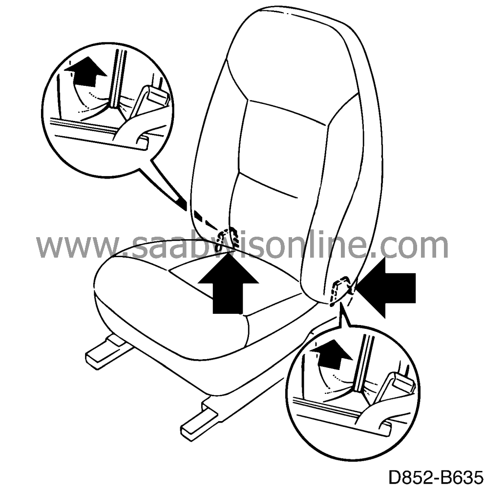
Three door cars with manual seats.
Remove the side covers.

|
|
3.
|
Three door cars with electrically adjustable seats without memory:
a Remove switch unit.
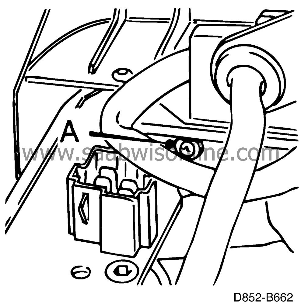
b Remove the side covers. The screw (A) is easily removed by using a flexible extension.
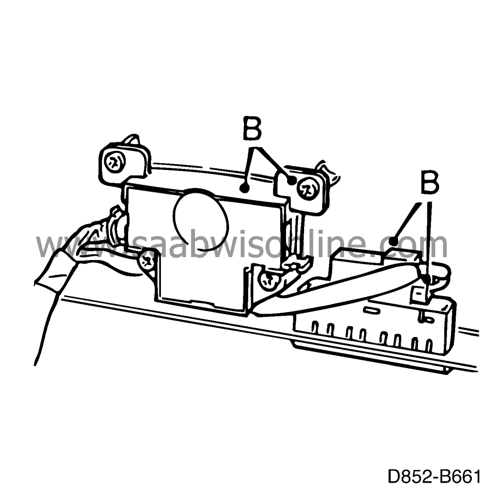
c Remove the control unit B from the cowl.
|
|
4.
|
Three door cars with electrically adjustable seats with memory:
a Remove switch unit.
b Remove the control module for the memory from the bracket.
c Remove the side covers. The screw (A) is easily removed by using a flexible extension.
d Remove the control unit (B) from the cowl.
|
|
5.
|
Five door cars with manual seats:
Remove the side cover.
|
|
6.
|
Five door cars with electrically adjustable seats without memory:
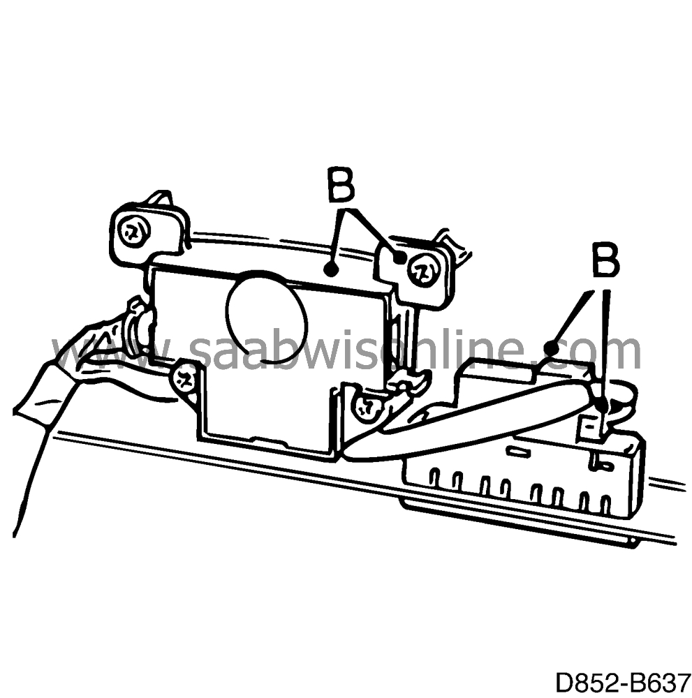
a Remove switch unit.
b Remove the side cover. The screw (A) is easily removed by using a flexible extension.
c Remove the control unit B from the cowl.
|
|
7.
|
Five door cars with electrically adjustable seats with memory:
|
|
|
7.a.
|
Remove switch unit.
Three door cars:
|
|
|
7.b.
|
Remove the control module for the memory from the bracket.
|
|
|
7.c.
|
Remove the side cover. The screw (A) is easily removed by using a flexible extension.
|
|
|
7.d.
|
Remove the control unit (B) from the cowl.
|
|
8.
|
Three door cars:

|
|
|
8.a.
|
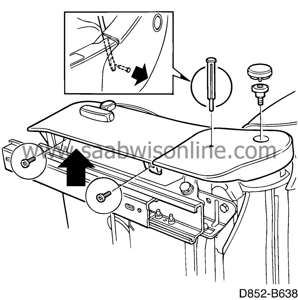
Remove the knob on the backrest release handle.
|
|
9.
|
Remove the head restraint.
|
|
10.
|
Remove the head restraint guide sleeves.

|
|
11.
|
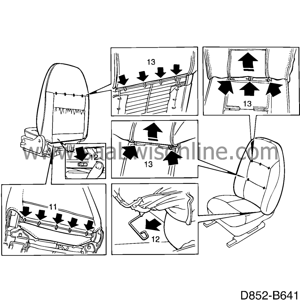
Cut the staples securing the lower edge of the back of the upholstery.
|
|
12.
|
Release the upholstery rods holding the front of the upholstery taut by bending out the metal tabs.
|
|
13.
|
Pull the backrest upholstery upwards and cut off the remaining stables. Pull off the seat upholstery.
|
|
14.
|
Cut off the staples that hold the foam cushion taut. Fold the foam cushion forward.

|
|
15.
|
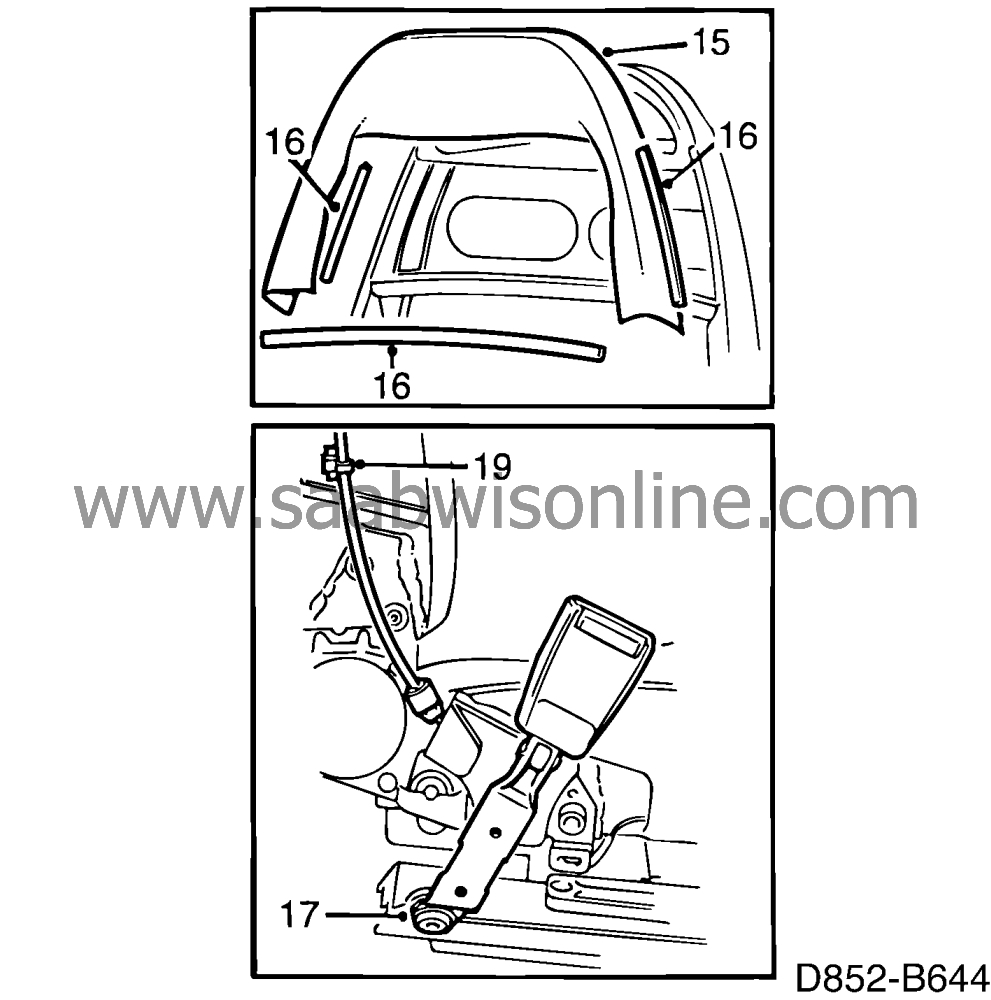
Remove the protective sheet from the backrest frame.
|
|
16.
|
Remove the edging strips on the backrest frame.
|
|
17.
|
Remove the seat belt buckle.
|
|
18.
|
Five door cars: Remove the belt from the anchorage on the seat.
|
|
19.
|
Three door cars:
|
Important
|
|
To ensure a satisfactory release function it is important that the release cable is fixed in the same position when fitting.
|
|
|
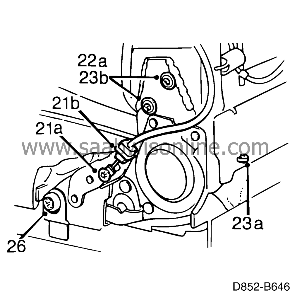
Note the position for the cable ties securing the backrest reclining cable and then cut off the cable tie.
Keep the washers from the clip attachment in the backrest frame. Passenger seats are equipped with double release handles and therefore double release cables.
|
|
20.
|
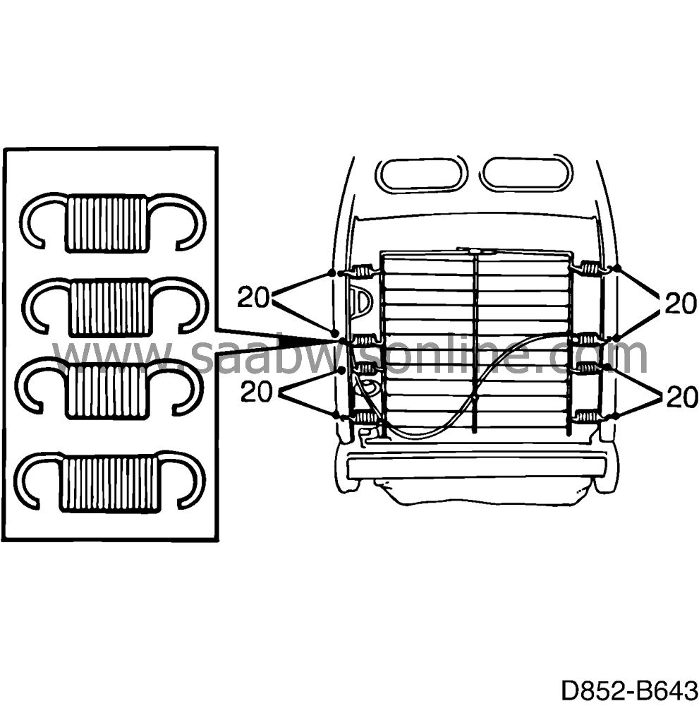
Note the position of the springs suspending the wire matting and then remove the springs and matting. The springs are of different strengths and should be refitted in the same position or the lumbar support will become impaired.
|
|
21.
|
Three door cars:
|
|
|
21.a.
|
Remove the catch washers securing the ends of the release cables.
|
|
|
21.b.
|
Remove the cable holders at the ends of the cables.
|
|
|
21.c.
|
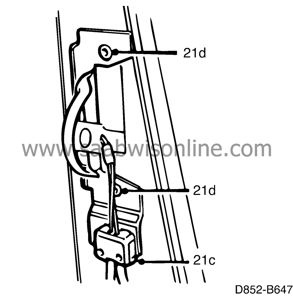
Remove the cable holder by the release handle.
|
|
|
21.d.
|
Drill out the blind rivets securing the release handle and remove the handle and cable.
|
|
22.
|
Seats with memory function:
|
|
|
22.a.
|
To enable measuring, remove the screws securing the backrest rake motor bracket.
|
|
|
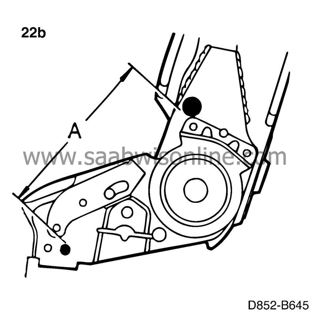
22.b.
|
Measure the backrest frame angle as shown in the illustration and note the value.
|
Important
|
|
The backrest frame must have the same angle when fitting as it had when being removed so that the potentiometer that reads the position of the backrest frame can give the correct value to the control module. If the control module receives incorrect values, it can cause the backrest rake motor to break down when adjusting the backrest angle.
|
|
|
|
|
23.
|
Electrically adjustable seats:
|
|
|
23.a.
|
Remove the clip securing the backrest rake motor wiring harness.
|
|
|
23.b.
|
Remove the screws securing the backrest rake motor bracket and remove the bracket on the other side. Put a protective cover over the seat cushion and place the motor on it.
|
|
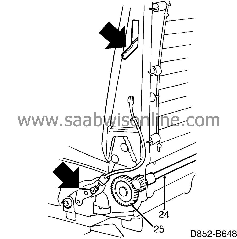
25.
|
Remove the ratchet segments.
|
|
26.
|
Remove the screws securing the backrest frame.
|
|
27.
|
Three door cars:
Blind rivet the release handle to the new backrest frame.
|
|
28.
|
Put the backrest frame in place and tighten the screws.

Tightening torque: 49 Nm (36 lbf ft)
|
|
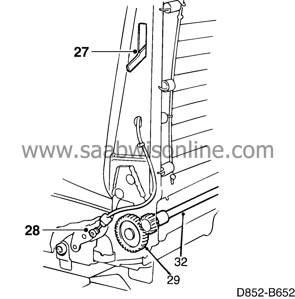
29.
|
Put the ratchet segments in place.
|
|
30.
|
Seats with memory function: Adjust the backrest angle as described in the illustration to the value that was noted on removal. The measured value ± 2 mm.
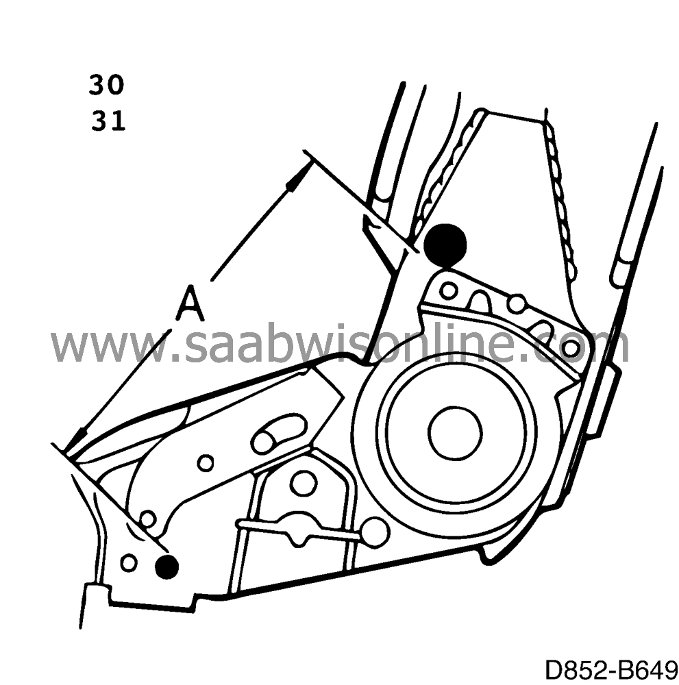
Adjust the parallelism by measuring dimension A so that it is the same on both sides of the backrest frame. The recorded measurement ± 0.3 mm.
|
Important
|
|
The backrest frame must have the same angle when fitting as it had when being removed so that the potentiometer that reads the position of the backrest frame can give the correct value to the control module. If the control module receives incorrect values it can cause the backrest rake motor to break down when adjusting the backrest angle.
|
|
|
|
|
31.
|
Electrically adjustable seats:
Adjust the parallelism by measuring dimension A so that it is the same on both sides of the backrest frame. The recorded measurement ± 0.3 mm.
|
Important
|
|
The backrest frame parallelism must be within the tolerance limit so that the backrest frame does not become askew and damage the ratchet segments.
|
|
|
|
|
32.
|
Put the shaft in place.
|
|
33.
|
Electrically adjustable seats:
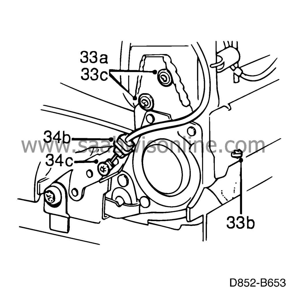
|
|
|
33.a.
|
Put the backrest rake motor in place and tighten the screws.
|
|
|
33.b.
|
Attach the wiring harness with a clip.
|
|
|
33.c.
|
Fit the bracket on the other side.
|
|
|
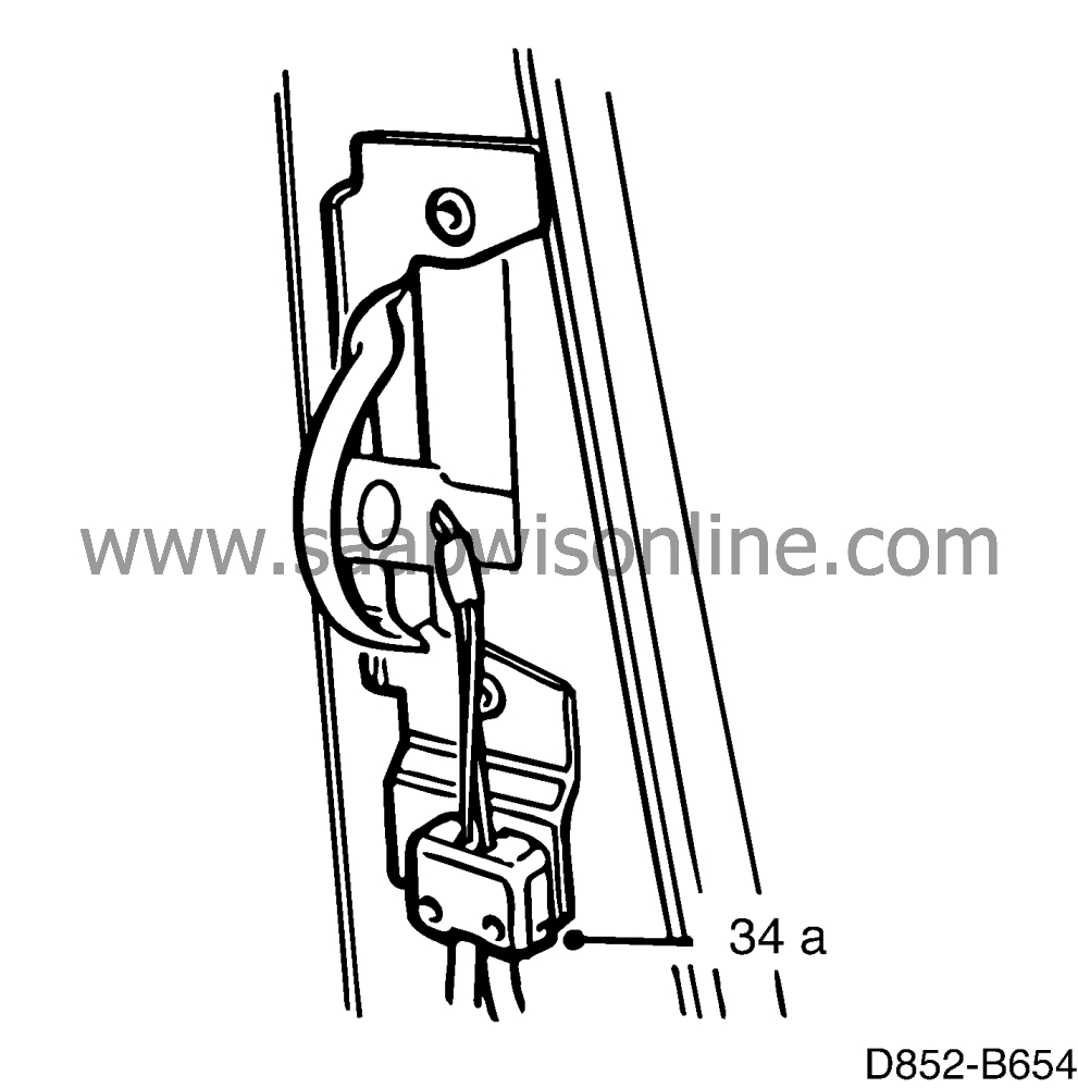
34.a.
|
Secure the release cable holder by the release handle and hook on the cable.
|
|
|
34.b.
|
Secure the ends of the cable in the holders.
|
|
|
34.c.
|
Put the ends of the cable in place and press on the catch washers.
|
|
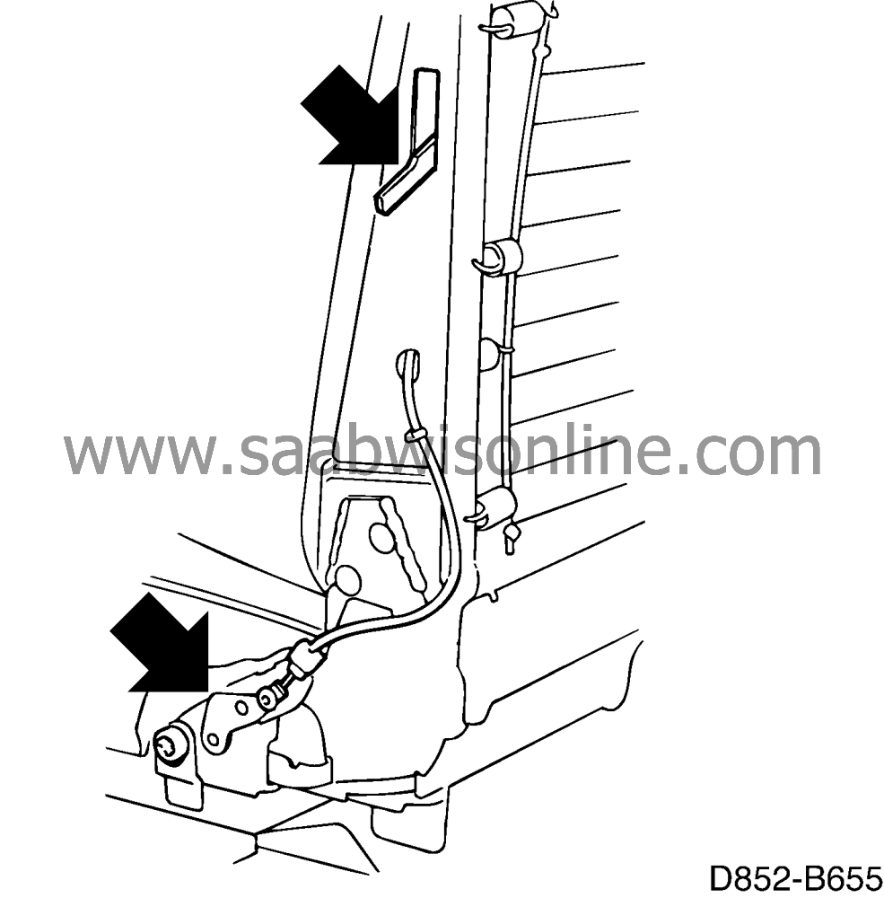
35.
|
Put the wire matting in place and hook on the springs according to the notes made on removal.

|
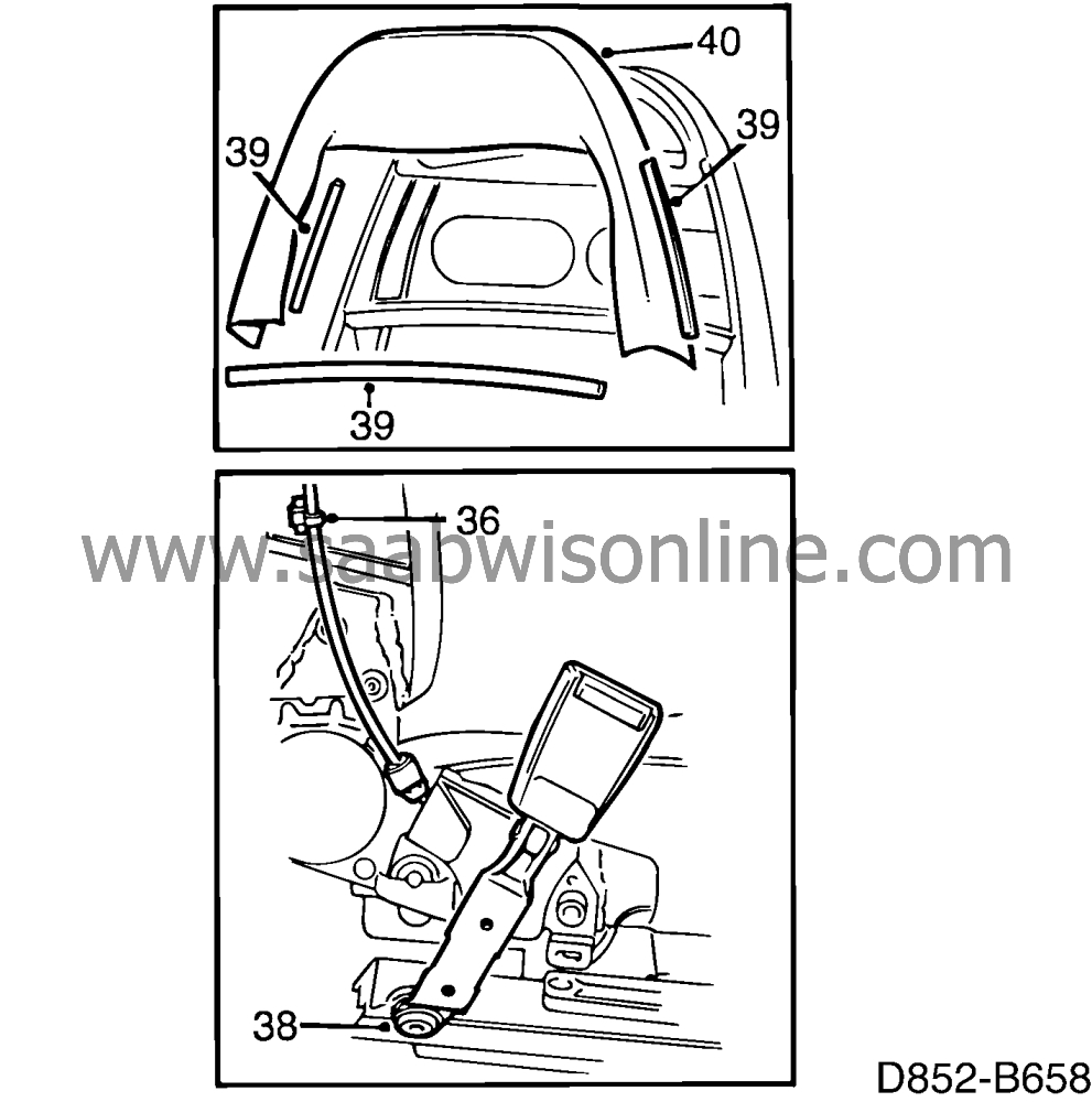
|
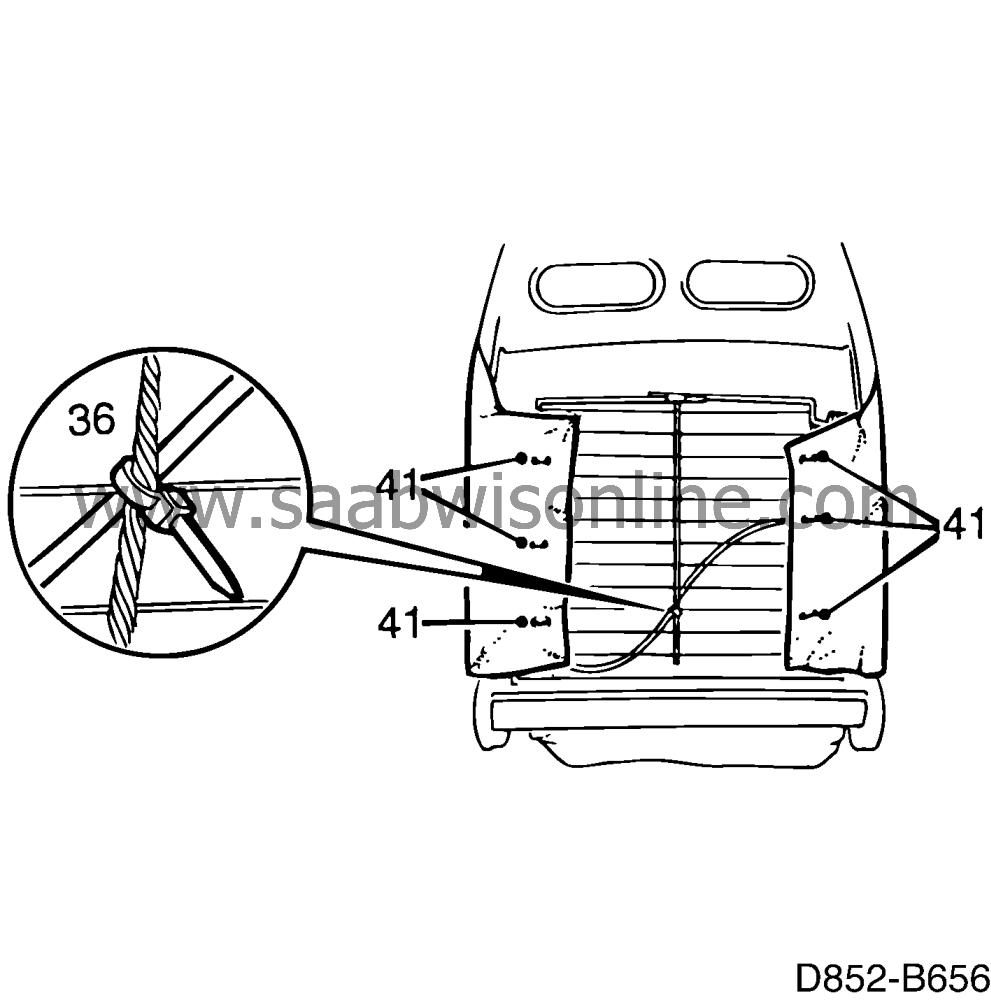
36.
|
Attach the release cable with clips according to the notes made on removal.
|
|
37.
|
Five door cars: Put the belt anchorage in place.
|
|
38.
|
Refit the seat belt buckle.
Tightening torque: 45 Nm (33 lbf ft)
|
|
39.
|
Press on the edging strips onto the backrest frame.
|
|
40.
|
Put the protective sheet in place.
|
|
41.
|
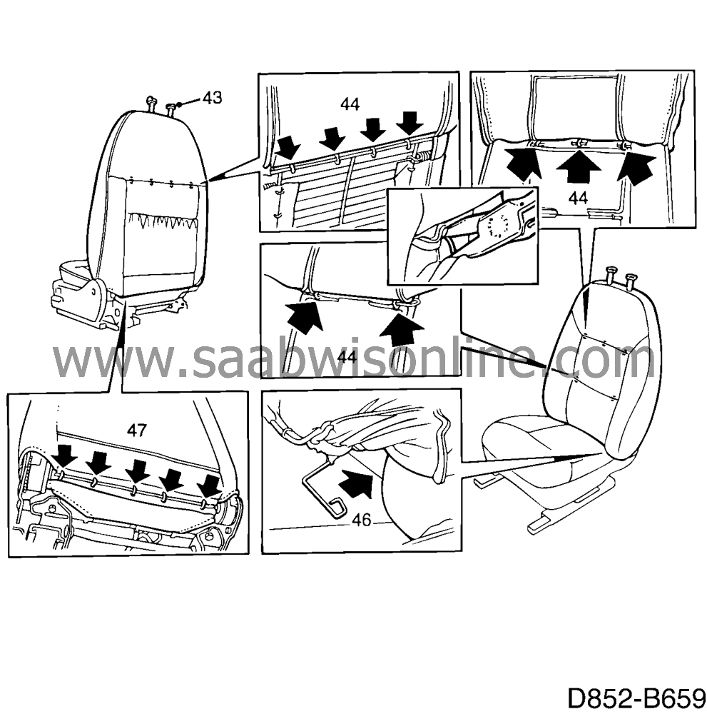
Put the foam cushion on the backrest frame. Wrap round the tension sheets and fit the staples using the pliers included in fitting kit 84 71 062.
|
|
42.
|
Slip on the upholstery to the first wire rod.
|
|
43.
|
Put the head restraint guide rails in place.
|
|
44.
|
Fit the staples securing the upholstery to the foam padding using the tool included in fitting kit 84 71 062.
|
|
45.
|
Press out the padding so that it fills the upholstery.
|
|
46.
|
Hook the rods into place and secure them by means of the metal tabs.
|
|
47.
|
Fix the lower edge of the upholstery by means of staples.
|
|
48.
|
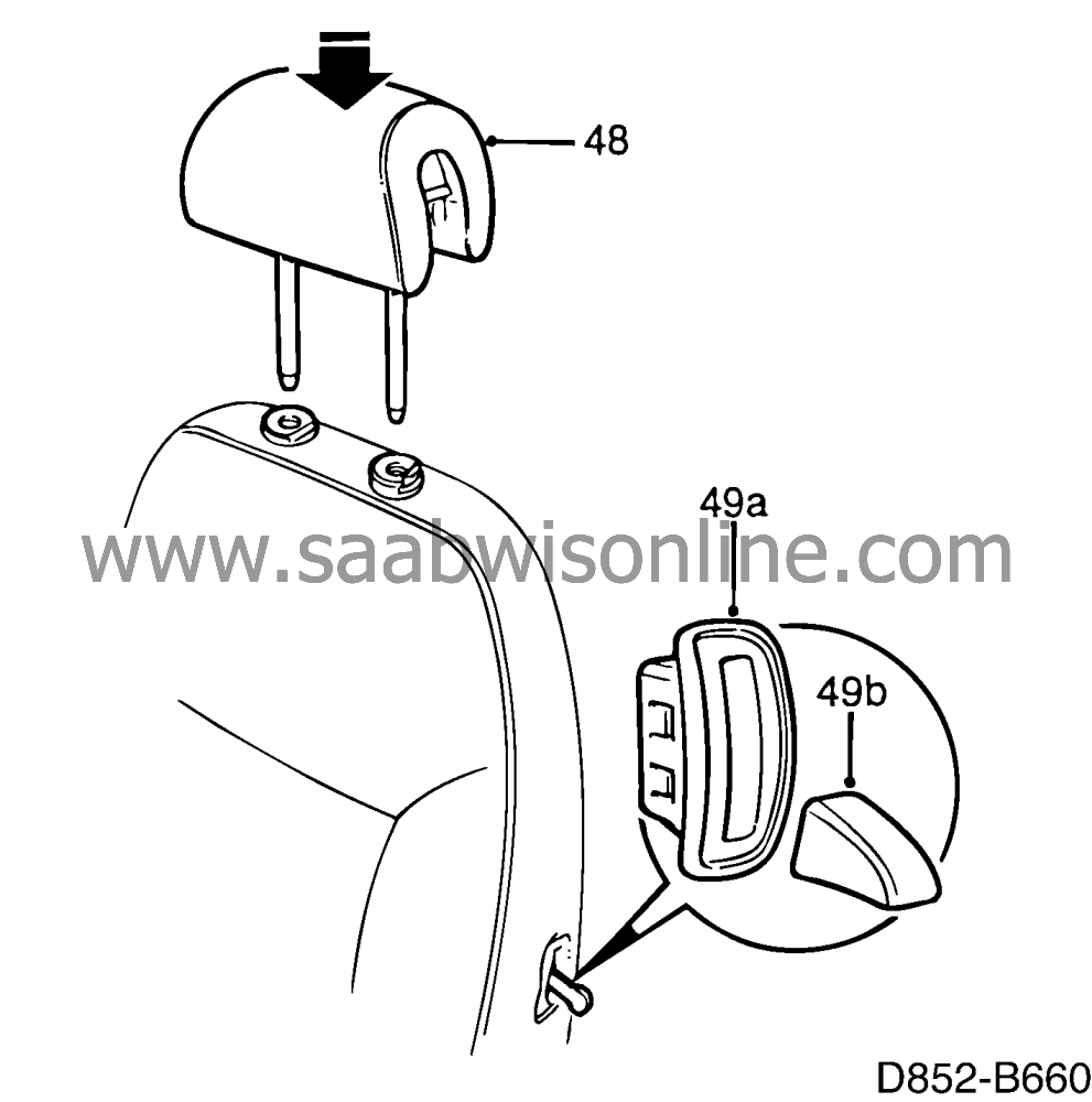
Refit the head restraints.
|
|
|
49.a.
|
Put in a new grommet in place at the reclining handle.
|
|
|
49.b.
|
Press on the knob on the reclining handle.
|
|
50.
|
Three door cars with manual seats:
Refit the side covers.
|
|
51.
|
Three door cars with electrically adjustable seats without memory:
|
|
|
51.a.
|
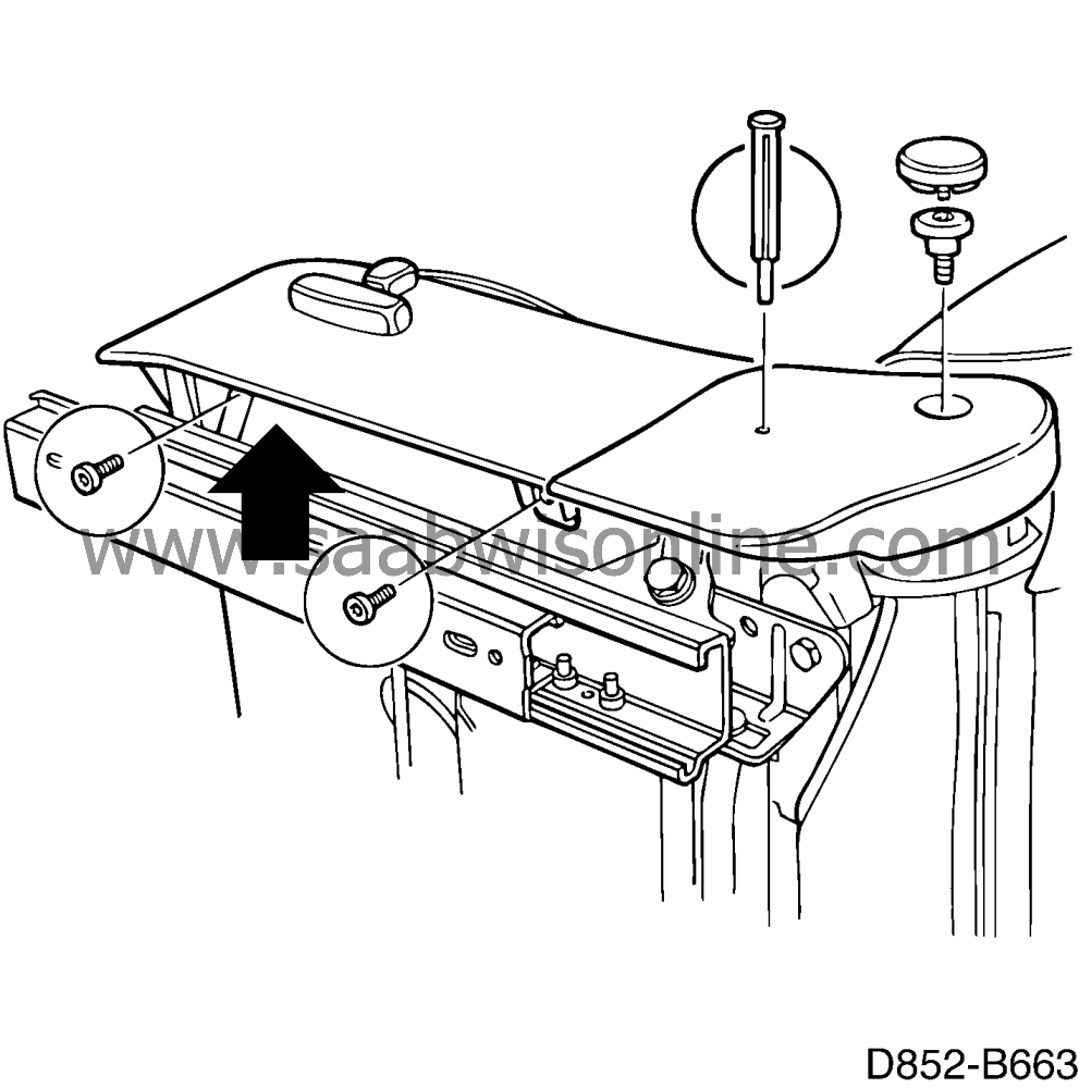
Fit the control unit (B) on the cowl
|
|
|
51.b.
|
Refit the side covers. The screw (A) is easily tightened using a flexible extension.
|
|
|
51.c.
|
Put the switch buttons in place.
|
|
52.
|
Three door cars with electrically adjustable seats with memory:
|
|
|
52.a.
|
Fit the control unit (B) on the cowl
|
|
|
52.b.
|
Refit the side covers. The screw (A) is easily tightened using a flexible extension.
|
|
|
52.c.
|
Put the switch buttons in place.
|
|
|
52.d.
|
Press on the control panel connection to the control module.
|
|
|
52.e.
|
Press the control module into the bracket.
|
|
53.
|
Five door cars with manual seats:
Refit the side covers.
|
|
54.
|
Five door cars with electrically adjustable seats without memory:
|
|
|
54.a.
|
Fit the control unit (B) on the cowl
|
|
|
54.b.
|
Refit the side cover. The screw (A) is easily tightened using a flexible extension.
|
|
|
54.c.
|
Put the switch buttons in place.
|
|
55.
|
Five door cars with electrically adjustable seats with memory:
|
|
|
55.a.
|
Fit the control unit (B) on the cowl
|
|
|
55.b.
|
Refit the side cover. The screw (A) is easily tightened using a flexible extension.
|
|
|
55.c.
|
Put the switch buttons in place.
|
|
|
55.d.
|
Press on the control panel connection to the control module.
|
|
|
55.e.
|
Press the control module into the bracket.
|
|
56.
|
Fit the seat in the car. See service manual 8:2 Interior equipment
 for five door cars and News Bulletin 0 M1995 for three door cars.
|
|
Warranty/Time information
|
See separate information.


 for five door cars and News Bulletin 0 M1995 for three door cars.


