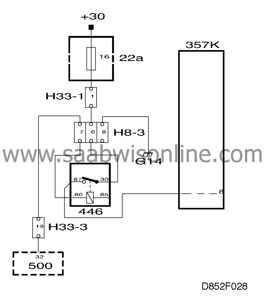
Checking the voltage supply
Symptom: Seat cannot be operated.
| Checking the voltage supply |
Fault symptom:
| • |
Seat cannot be operated.
|
|
Diagnostic procedure:
| 1. |
Check that fuse 16 is intact.
|
|
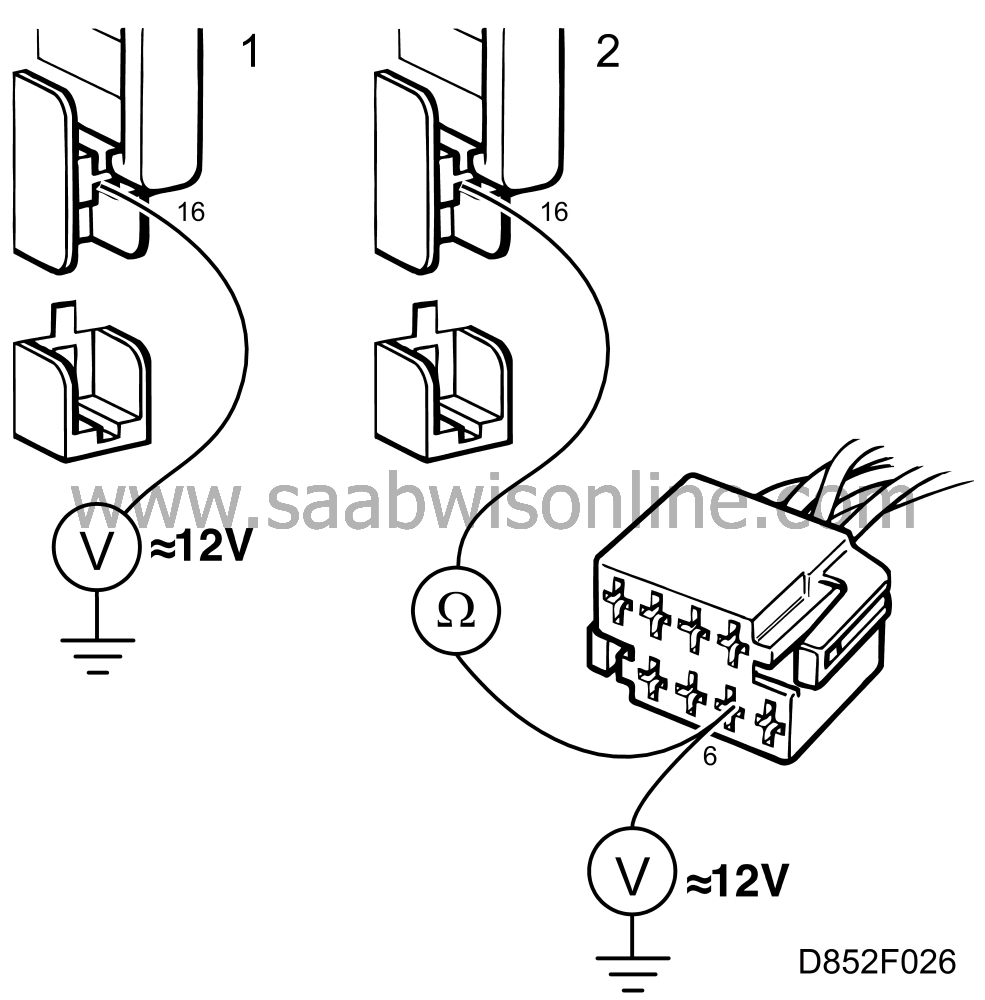
| 2. |
Unplug the 8-pin connector under the seat and measure the voltage across pin 6 and chassis ground. It should be 12 V. If it is not, check the wiring between pin 6 of the connector and fuse 16.
|
|
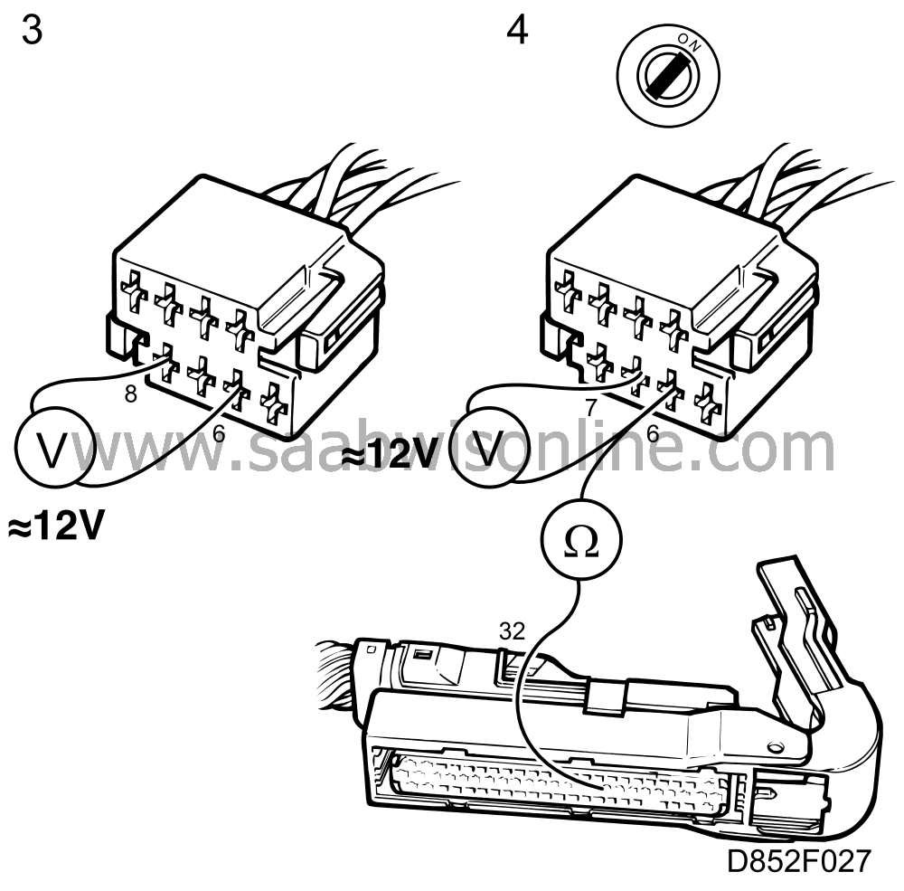
| 3. |
Measure the voltage across pins 6 and 8. It should be 12 V.
|
|
| 4. |
Measure the voltage across pins 6 and 7 in the connector. It should be about 12 V when a door is open or the ignition switched on, and 0 V when all doors are closed and the ignition is switched off. If different readings are obtained, check the wiring between pin 7 and ICE terminal 32 for continuity/shorting.
|
|
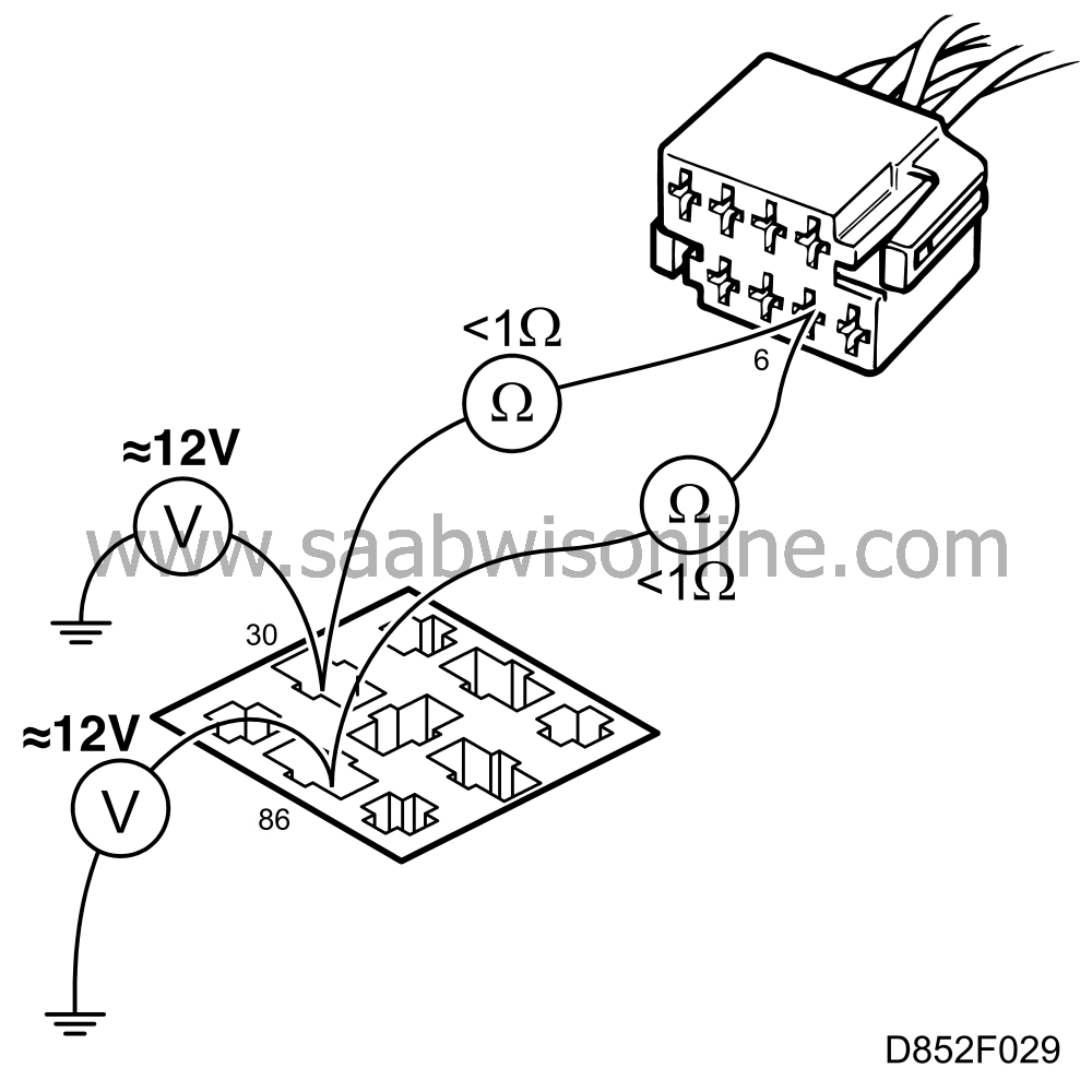
| 5. |
Remove the relay and check whether 12 V is present across pin 30 and ground and across pin 86 and ground. If it is not, check the wiring between pin 6 of the 8-pin connector and pin 30 or 86 of the relay.
|
|
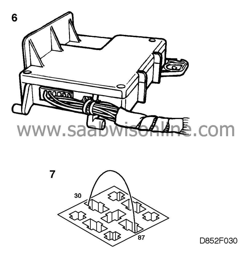
| 6. |
Connect a jumper lead across pins 30 and 87 of the relay holder. If the seat can now be operated, change the relay.
|
|
| 7. |
Check the wiring between pin 87 of the relay and the control module.
|
|
| 8. |
Turn to page 852-55, "Before control module replacement".

|
|
This project is supported by memberships and donations. If you use this site, please consider Joining SCNA and/or making a donation.
Our Friends
