Removal
| Removal |
|
||||||||||
| 1. |
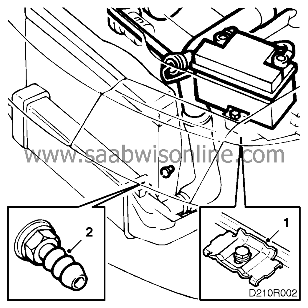
Drape protective covers over the wings to protect the paintwork and remove the battery.
|
|
| 2. |
Open the drain plug and drain the coolant. Remove the filler cap on the expansion tank to speed up the process.
|
|
| 3. |
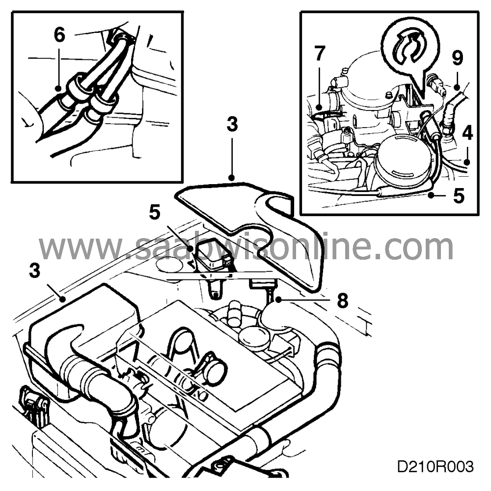
Remove the air cleaner complete with hoses. Remove the cover or resonator.
|
|
| 4. |
Detach the throttle cable and bend it aside.
|
|
| 5. |
Disconnect the Cruise Control cable from the throttle body, unplug the Cruise Control connector, undo the retaining bolts and remove the Cruise Control unit complete with cable.
|
|
| 6. |
Detach the fuel hoses and plug them. Use tool 83 94 702 or 83 95 261.
|
|
| 7. |
Disconnect the tank breather hose and bend it to one side.
|
|
| 8. |
Remove the pressure sensor and place it on the engine (turbo).
|
|
| 9. |
Disconnect the vacuum hose for secondary air injection (certain cars) and disconnect the brake servo vacuum hose from the intake manifold.
|
|
| 10. |
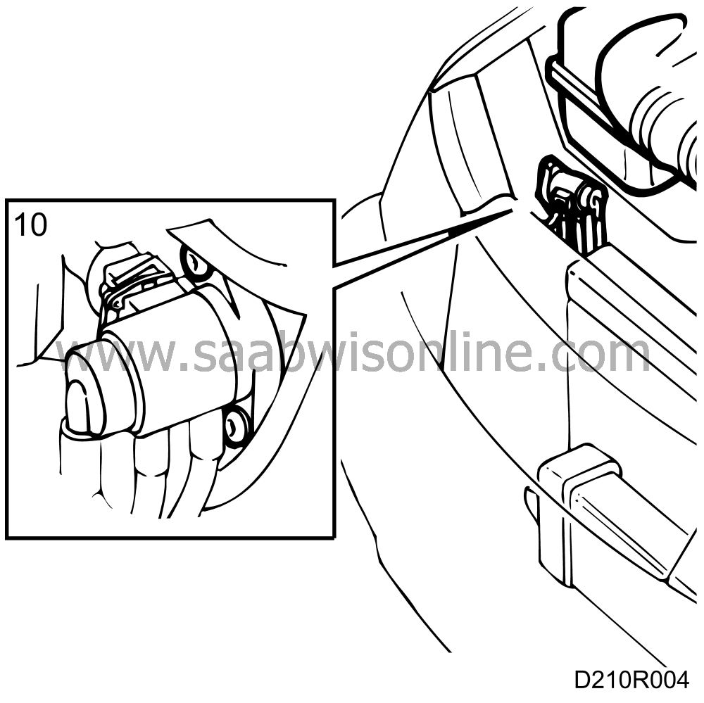
Remove the boost pressure control (BPC) and place it on the engine (turbo).
|
|
| 12. |
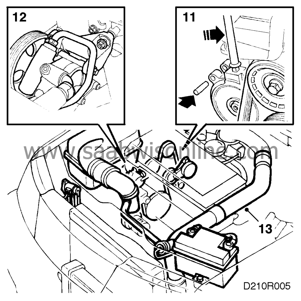
Remove the servo pump from the bracket and set it aside.
|
|
| 13. |
Remove the delivery pipe between the charge air cooler and the throttle body (turbo).
|
|
| 14. |
Remove the coolant hoses.
|
|
| 15. |
Remove the hose for secondary air injection (certain cars).
|
|
| 16. |
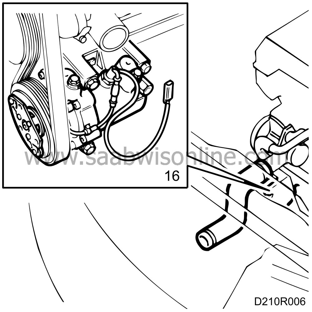
Unplug the A/C compressor's connector and remove the compressor's upper retaining bolts (A/C).
|
|
| 17. |
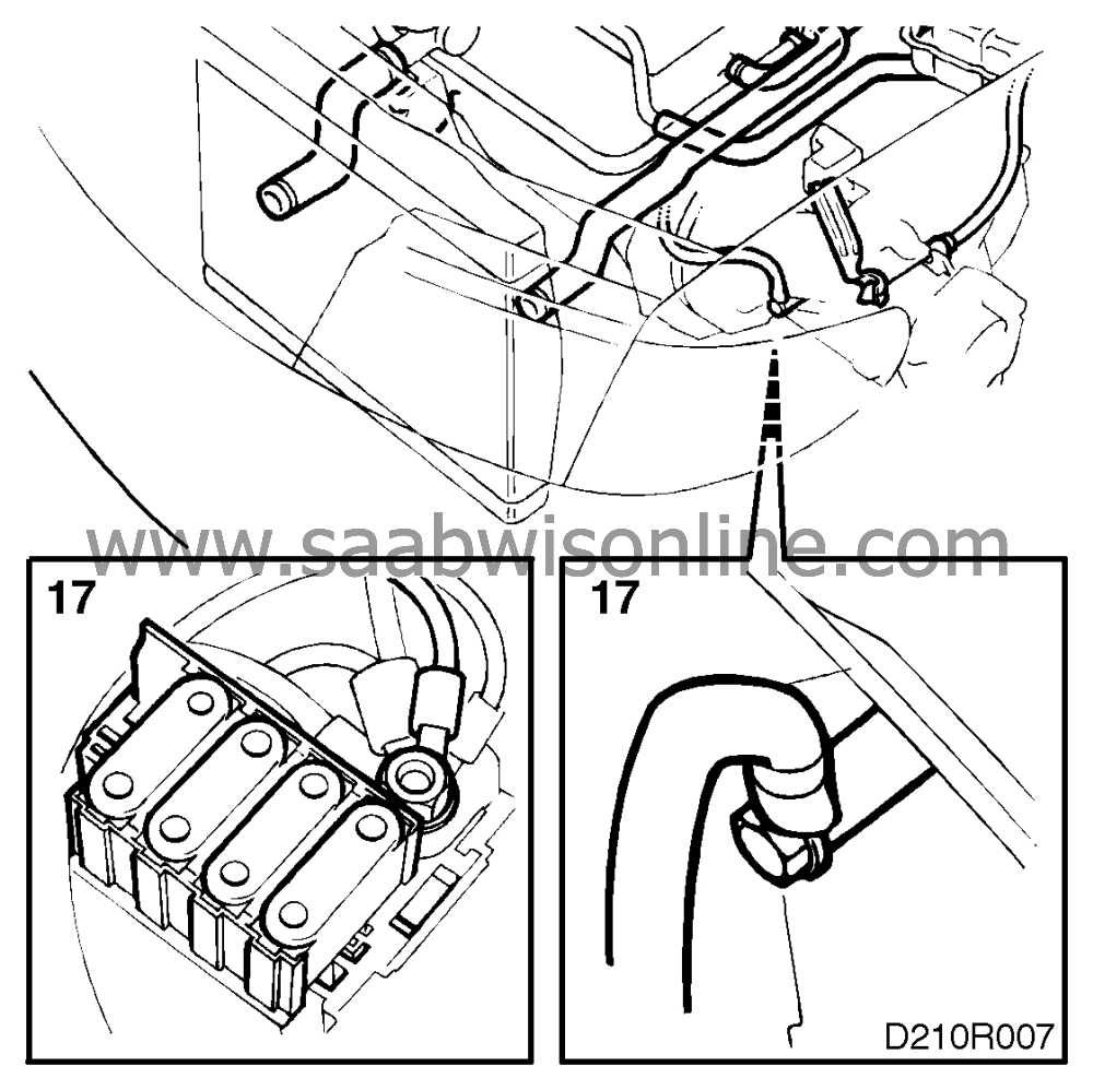
Disconnect the positive lead from the positive terminal block (on the engine) and disconnect the ground cable from the gearbox.
|
|
| 18. |
Remove the ignition cable and the electrical leads from the ignition coil (B206i B234i).
|
|
| 19. |
Unplug the gearbox connectors and place them on the engine.
|
|
| 20. |
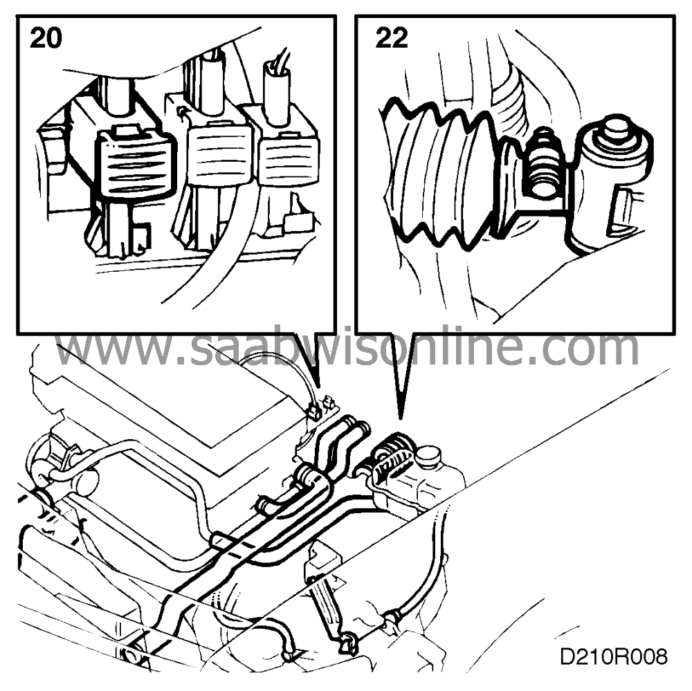
Disconnect the oxygen (Lambda) sensor lead and (in certain markets) the catalytic converter temperature warning lead.
|
|
| 21. |
Remove the breather hose from the gearbox and plug the hole (automatic transmission).
|
|
| 22. |
Remove the selector lever cable (automatic transmission) or separate the selector rod (manual gearbox/SENSONIC).
|
|
| 23. |
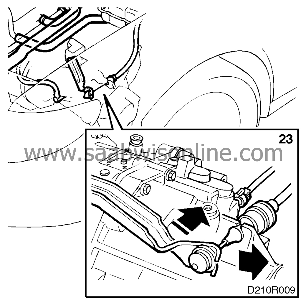
Disconnect the clutch cable (manual gearbox) or disconnect the clutch pipe and plug it (SENSONIC).
|
|
| 24. |
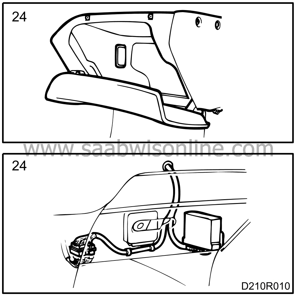
Remove the glove box (LHD) or the lower part of the panel on the right-hand side (RHD), fold back the carpet and unplug the control module for the central locking system. Remove the wiring for the engine.
|
|
| 25. |
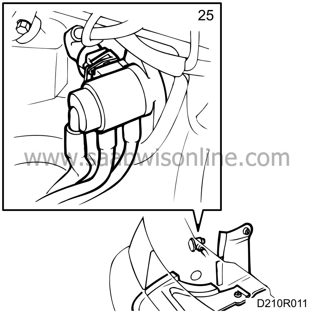
Pull the wiring through the grommet into the engine bay and place it on the engine. Do not forget the lead running to the boost pressure control valve (BPC) (turbo).
|
|
| 26. |
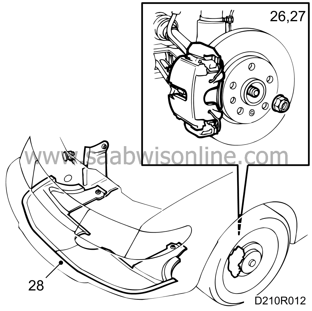
Slacken the hub nuts on both sides and raise the car.
|
|
| 27. |
Remove the covers in the wheel housings and the spoiler sections.
|
|
| 28. |
Remove both front wheels and the hub nuts. Detach the brake calipers and hang them on the suspension struts. Make sure that brake hoses, etc. are not damaged. Remove the nut for the end piece, steering swivel member on both sides.
|
|
| 29. |
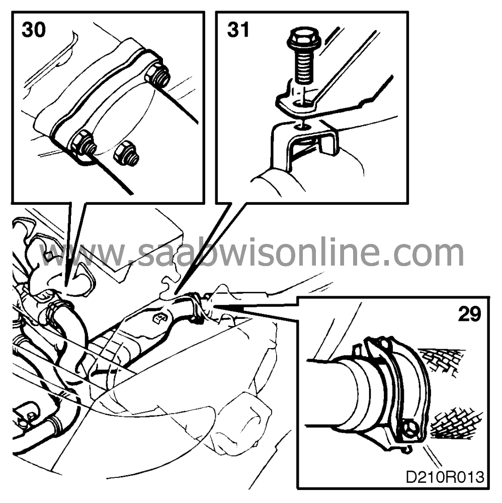
Undo the joint between the front pipe and the intermediate pipe.
|
|
| 30. |
Detach the front exhaust pipe from the rubber mountings and exhaust manifold or turbocharger.
|
|
| 31. |
Detach the catalytic converter from the mounting or rubber suspension and remove the exhaust pipe.
|
|
| 32. |
Place a receptacle under the gearbox, disconnect the gearbox oil hoses from the gearbox and plug the holes. Move the hoses aside (automatic transmission).
|
|
| 33. |
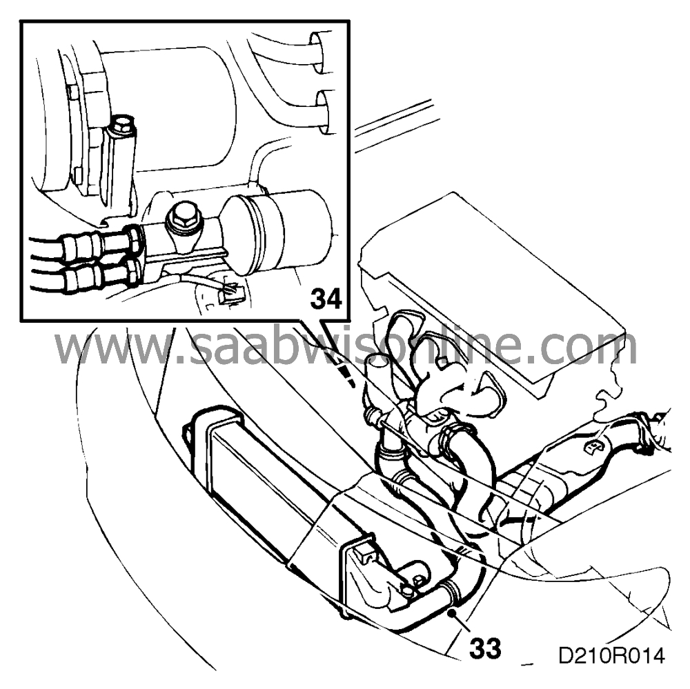
Remove the pipe between the turbocharger and the charge air cooler (turbo).
|
|
| 34. |
Disconnect the oil hoses from the oil cooler and plug them (turbo).
|
|
| 35. |
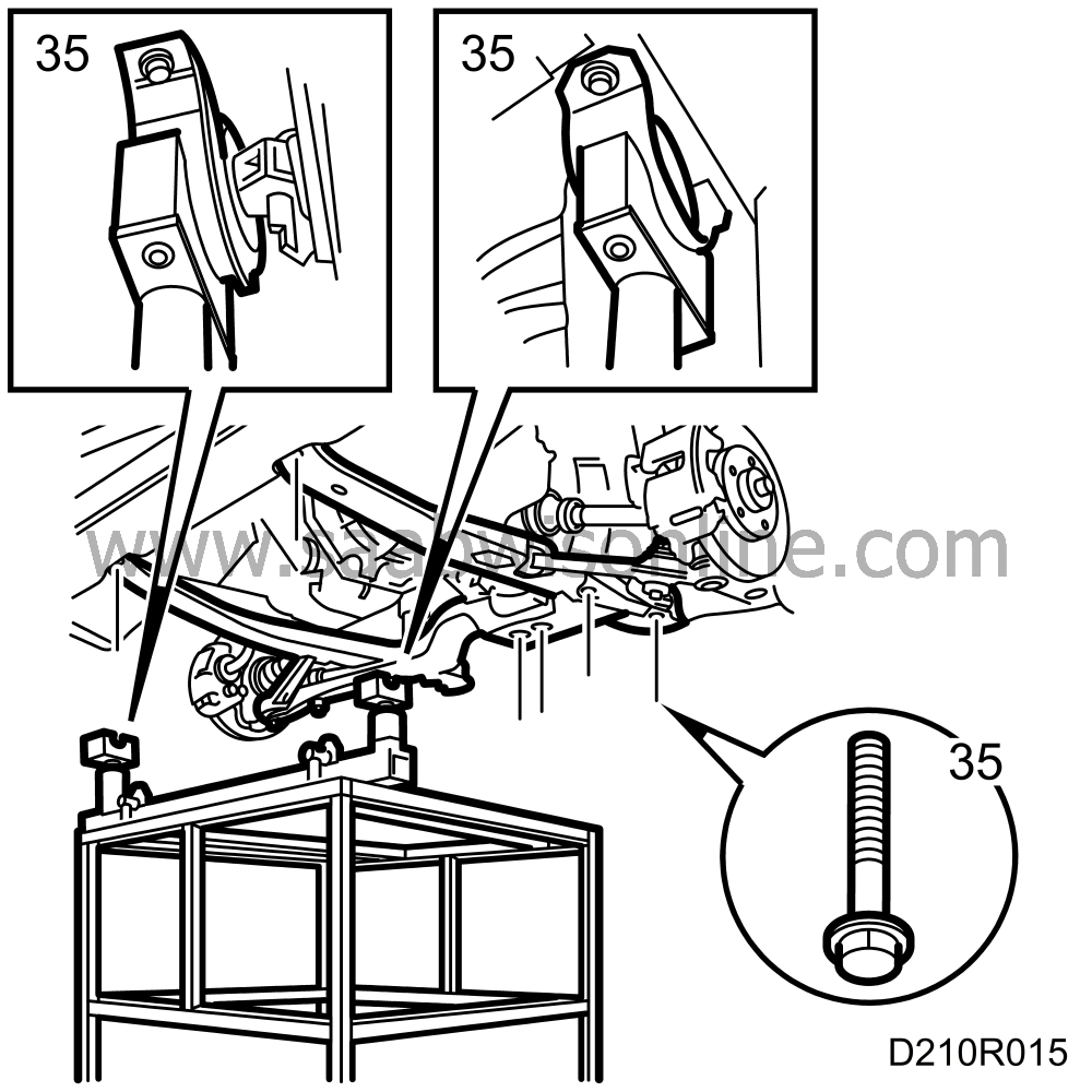
Run a lifting table under the car and position it so that its supports are directly below the front engine mountings and the gearbox. Remove the retaining bolts for the subframe and front engine mountings. Use tools 83 94 793 Lifting cart, 83 94 801 Parent fixture, 83 94 819 Front holder and 83 94 827 Rear holder
|
|
| 36. |
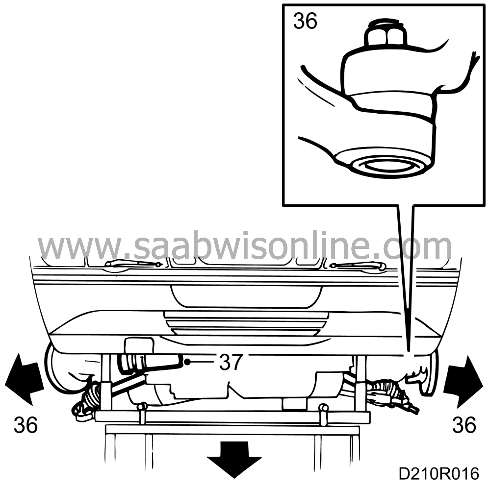
Lower the lifting table slightly and with it the power train and subframe. Remove the end pieces and drive shafts on both sides. Use puller 89 96 696.
|
|
| 37. |
Remove the A/C compressor and hang it from the towing eye with a strap.
|
|
| 38. |
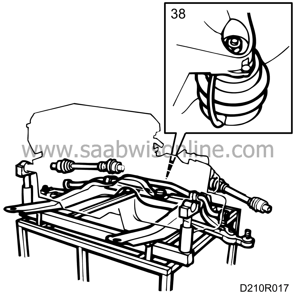
Lower the lifting table fully and remove the rear engine mounting from the gearbox and then remove the sub-frame.
|
|

 Warning
