Cylinder head, rear (1-3-5)
|
|
Cylinder head, rear (1-3-5)
|
 Warning
|
|
The camshafts must not be rotated because the valves could touch the pistons or each other and become damaged. The crankshaft may only be turned between 0° and 60° BTDC when the camshafts of both cylinder heads are locked with locking tools.
|
|
|
|
|
|
|
1.
|
Drape the wings with protective covers, drain the radiator of coolant and disconnect the negative cable from the battery.
|
|
2.
|
Raise the car and remove the two bolts securing the front exhaust pipe to the exhaust manifold.
|
|
3.
|
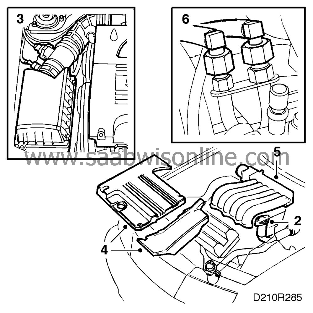
Lower the car and remove the air cleaner and the mass air flow sensor.
|
|
4.
|
Remove the engine covers.
|
|
5.
|
Remove the intake manifold and lift it up. Plug the holes with paper. Then disconnect:
|
|
|
•
|
the hose from the fuel pressure regulator
|
|
|
•
|
the secondary air injection vacuum hose (where fitted)
|
|
|
•
|
the IAC valve connector
|
|
|
•
|
the TCS throttle body connector
|
|
|
•
|
the coolant hoses to the throttle body
|
|
|
•
|
the hose to the evaporative (EVAP) emission canister air purging valve
Lift away the intake manifold.
|
|
6.
|
Disconnect the fuel lines and plug the connectors.
|
|
7.
|
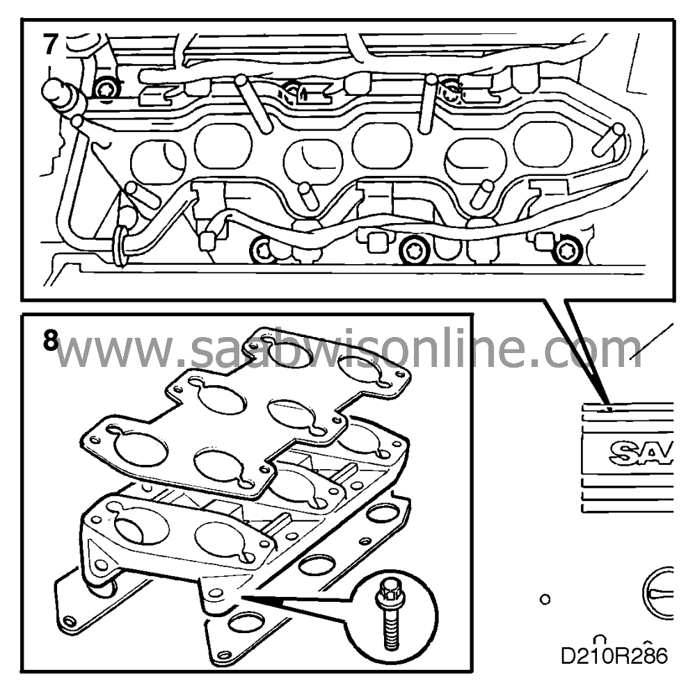
Remove the bolts securing the centre intake manifold complete with fuel rail and place it to one side.
|
|
8.
|
Remove the gaskets to gain access to all the retaining bolts securing the lower section of the intake manifold. Remove the lower section and plug with paper.
|
|
9.
|
Unplug the electrical connectors, the coolant hose and remove the coolant bridge.

|
|
10.
|
Disconnect HT leads 1-3-5 and remove the spark plugs.
|
|
11.
|
Remove the oxygen sensor's connector from its holder and remove the closed-circuit crankcase ventilation housing. Plug the holes with paper.
|
|
12.
|
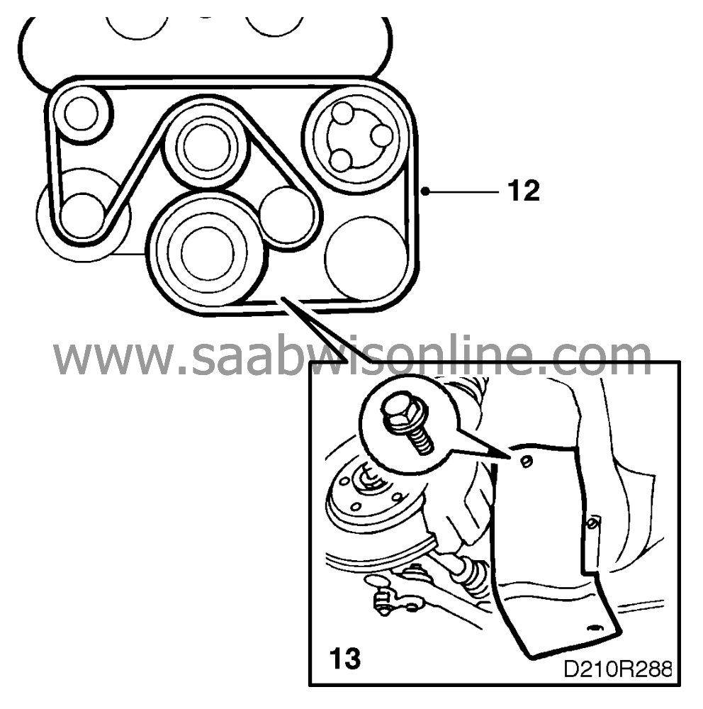
Slightly loosen the bolts securing the crankshaft pulley. Remove the multigroove drive belt, the belt tensioner, the power steering pump pulley, the coolant pump pulley and the cover.
|
|
13.
|
Remove the right-hand front wheel and the cover in the wheel housing. Remove the crankshaft pulley (undo the six bolts but do
not
remove the centre bolt).
|
|
14.
|
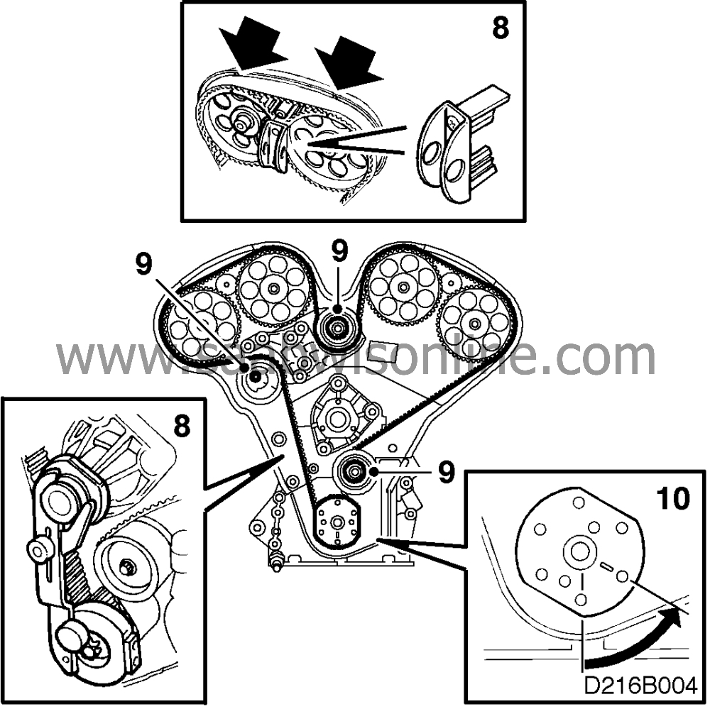
Zero the engine. The markings on the camshaft sprockets and timing cover should be in alignment as also should the marking on the crankshaft. Use tool KM-800-20. Fit locking tools KM-800-1 and KM-800-2 for the camshaft sprockets and locking tool KM-800-10 for the crankshaft.
|
|
15.
|
Before removing the toothed belt,
mark its direction of rotation
. To facilitate refitting, the belt can be marked at both the camshaft marking and at the crankshaft marking.
|
|
16.
|
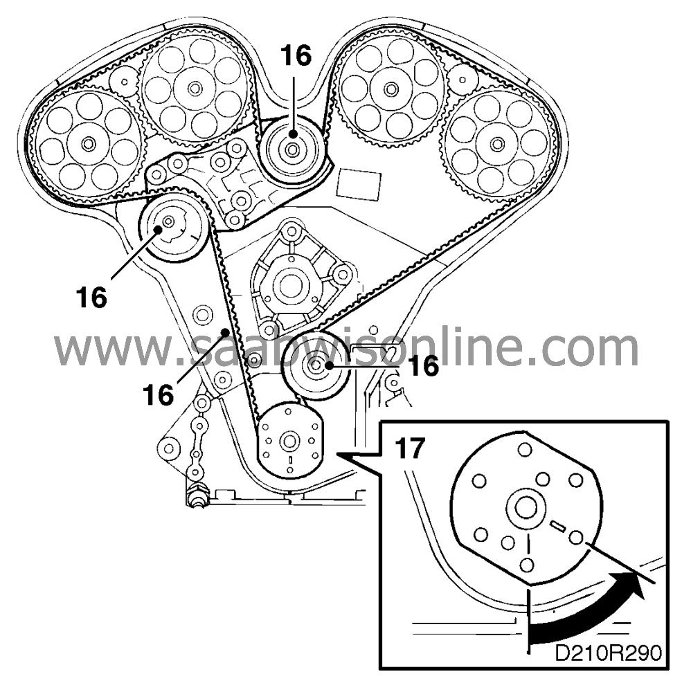
Release the belt tension and remove the toothed belt. Undo the bolts for the adjusting rollers.
|
|
17.
|
Turn the crankshaft back to 60 degrees BTDC.
|
|
18.
|
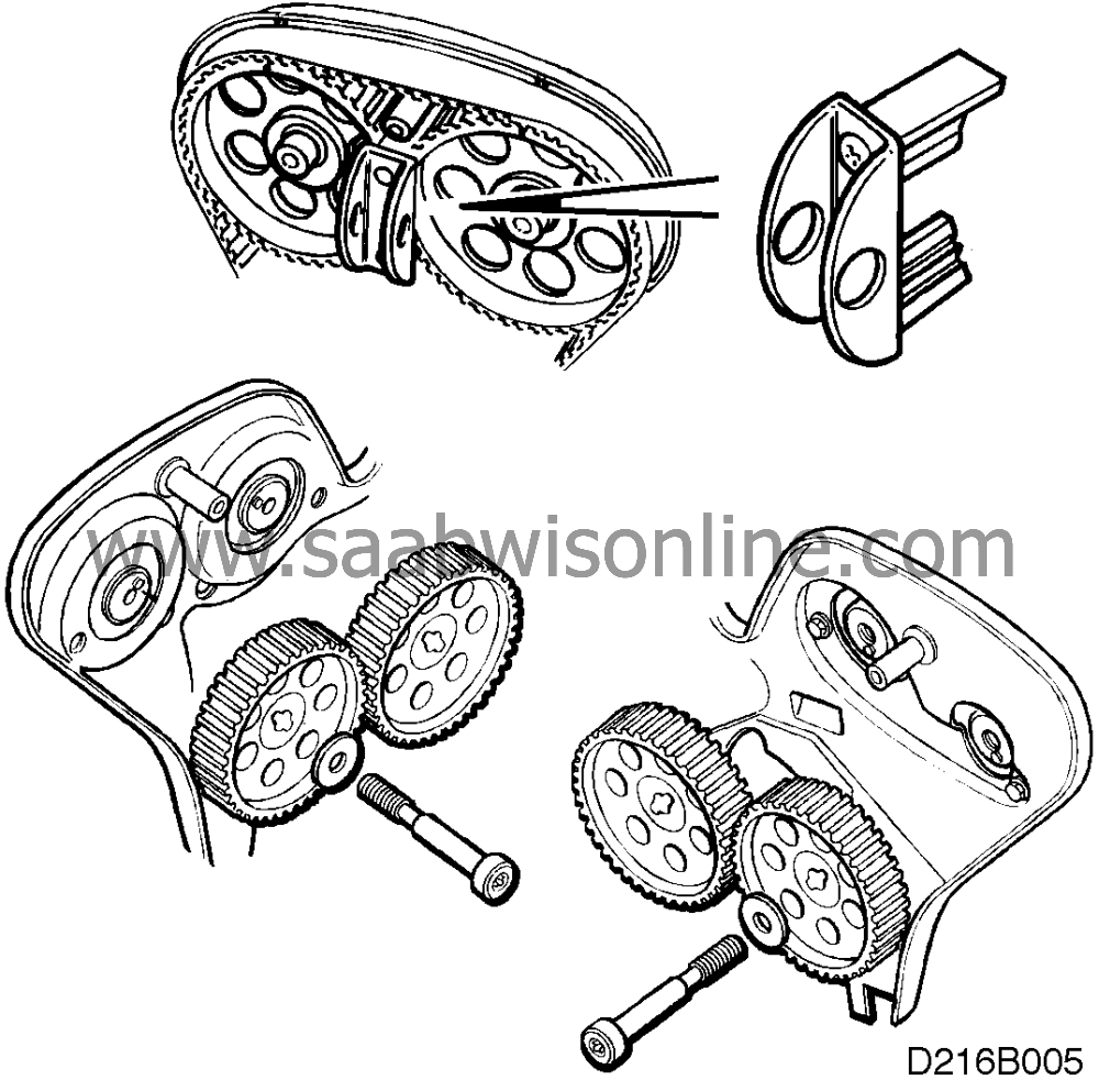
Remove the camshaft sprocket bolts and remove the tool and sprockets.
|
|
19.
|
Undo the belt tensioner bracket bolts and lift out the belt tensioner.

|
|
20.
|
Remove the coolant pump. Be careful with the O-ring.
|
Important
|
|
There is quite a lot of coolant left in the engine. Always have a receptacle under the engine when you work on the radiator system.
|
|
|
|
|
21.
|
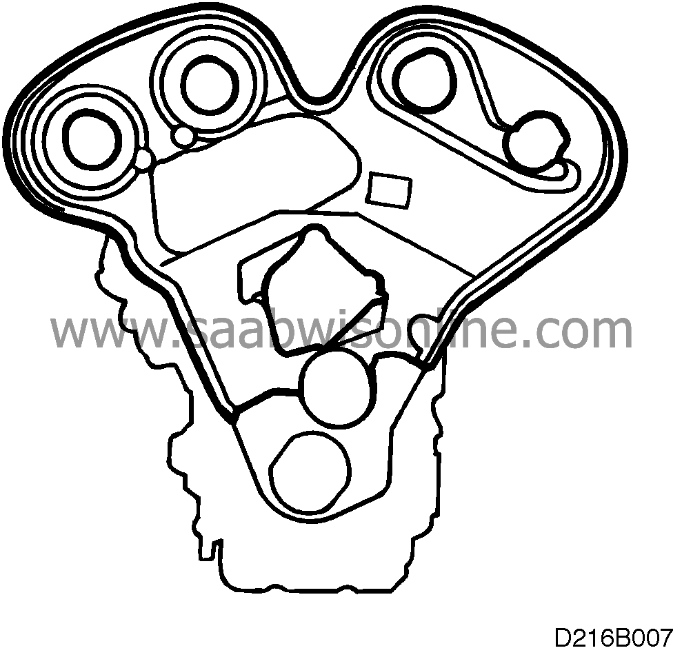
Remove the inner timing cover.
|
|
22.
|
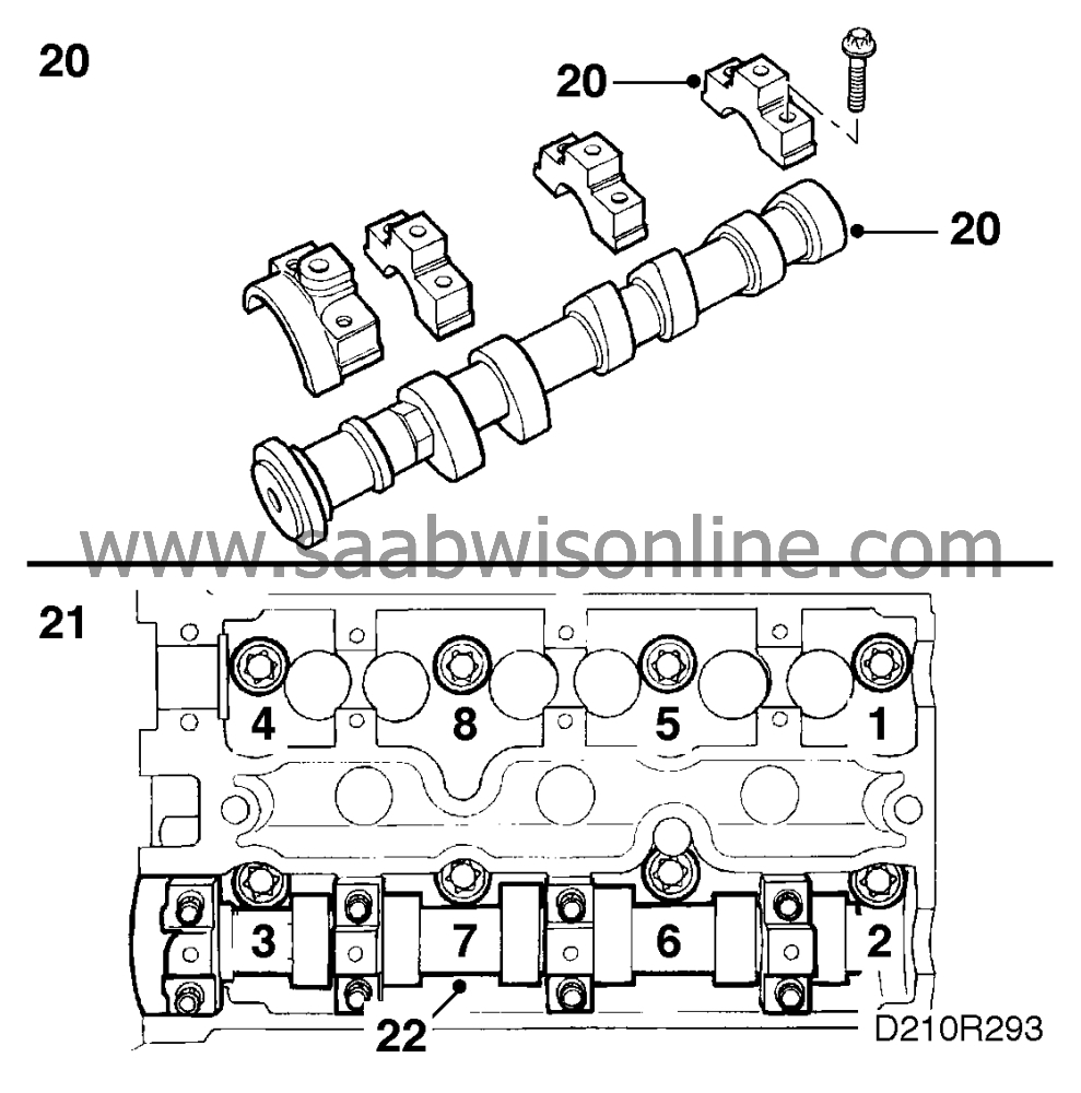
Remove the bearing caps on the exhaust camshaft. it is important to finish removal at the bearing cap where the valve tappets are under load. Pay attention to the marking on the bearing caps.
 Warning
|
|
Undo the bolts in stages, 1/2 to 1 turn at a time. Exercise care as the threads could easily be damaged.
|
|
|
|
|
|
Remove the camshaft seal and lift out the camshaft.
|
Note
|
|
The intake camshaft need not be removed when removing the cylinder head.
|
|
|
23.
|
Undo the cylinder head bolts in the order shown. First slacken them a 1/4 turn and then 1/2 a turn. Lift off the cylinder head. Be careful when putting it down as the intake camshaft is still in place and the valve stems could be bent accidentally.
|
|
24.
|
Remove the intake camshaft, exhaust manifold and tappets.
|
|
1.
|
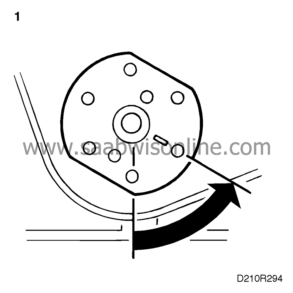
Make sure that the crankshaft is positioned at 60° BTDC.
|
|
2.
|
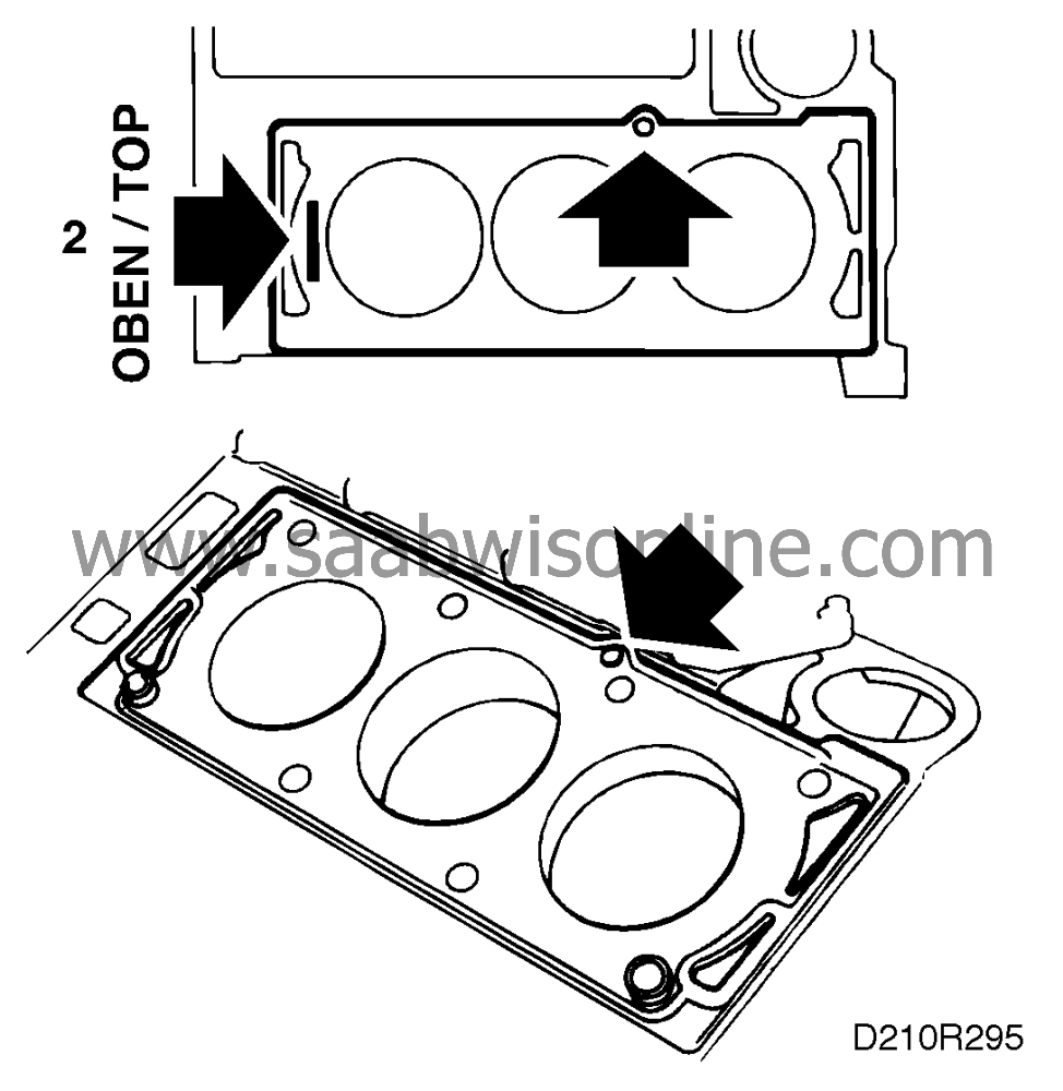
Clean all contact surfaces and fit the gasket. Note the guides for the gasket and that it is marked OBEN/TOP.
|
|
3.
|
Fit the exhaust manifold and the valve depressors.
|
|
4.
|
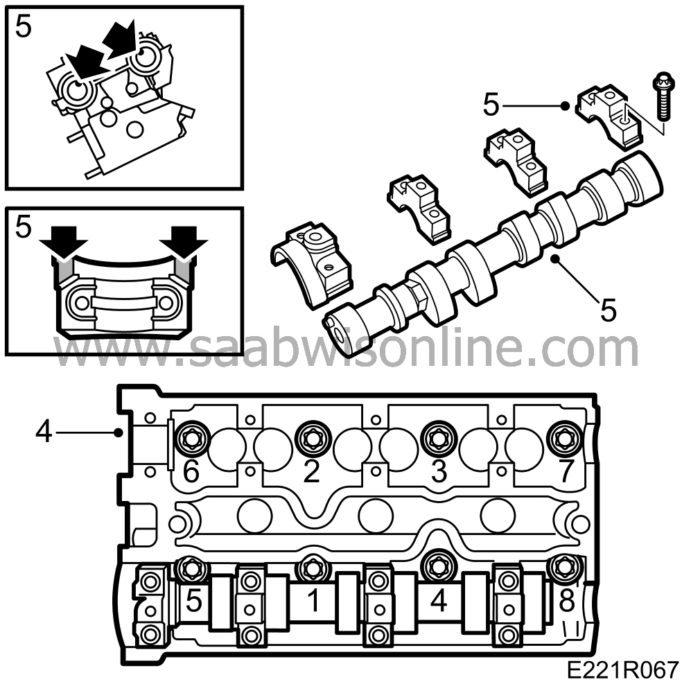
Place the cylinder head in position. Use new bolts. Tighten in the order shown.
Tightening torques
Stage 1: 25 Nm (18.5 lbf ft)
Stage 2: Tighten to 90°
Stage 3: Tighten to 90°
Stage 4: Tighten to 90°
|
|
5.
|
Place the camshafts in position and lubricate them
generously
with oil. Make sure that the locating pins are in position as shown.
Pay attention to the markings on the bearing caps and in the cylinder head. Smear flange sealant, part No. 93 21 795, sparingly on the surfaces of the front bearing caps that are in contact with the cylinder head.
Fit the bearing caps and tighten the bolts in the order shown. Tighten them in stages, 1/2 to 1 turn at a time.
Turning torque 8 Nm (6 lbf ft).
|
|
6.
|
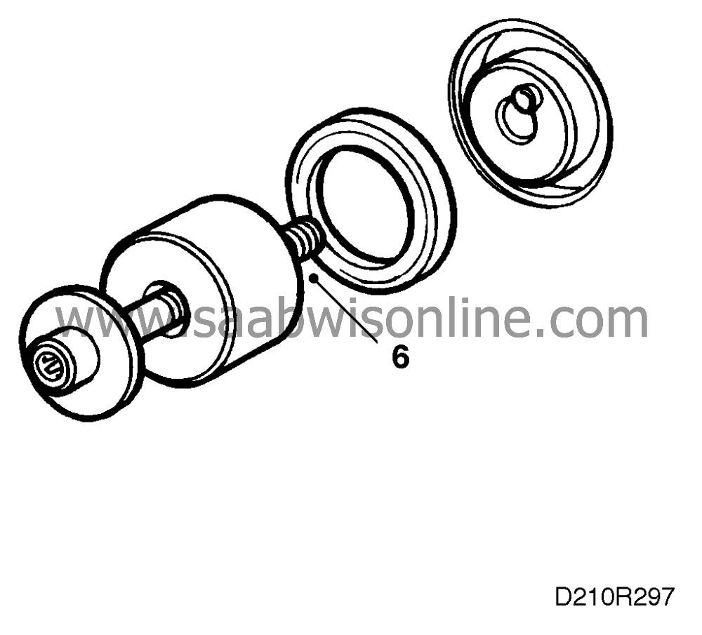
Lubricate the sealing lips and fit the gasket (using tool 83 94 959) and camshaft bolt and washer.
|
|
7.
|
Position the new inner timing cover. Apply thread locking compound 74 96 268 to the bolts and tighten them.
|
|
8.
|
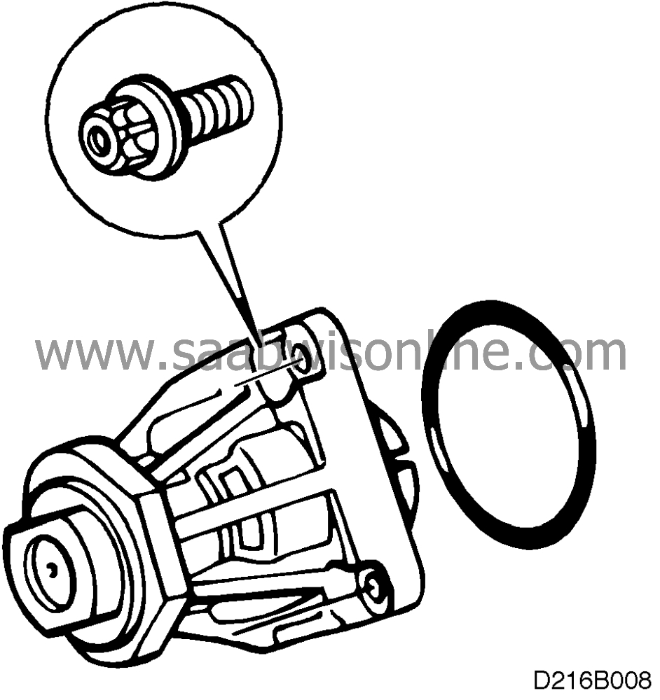
Clean the coolant pump's sealing surfaces and fit a new O-ring.
|
|
9.
|
Apply acid-free vaseline to the sealing surfaces and the O-ring and fit the coolant pump.
|
|
10.
|
Fit the camshaft sprockets. Check their positions against the markings in the timing cover. Lock them with tools KM-800-1 and KM-800-2 and tighten the bolts.
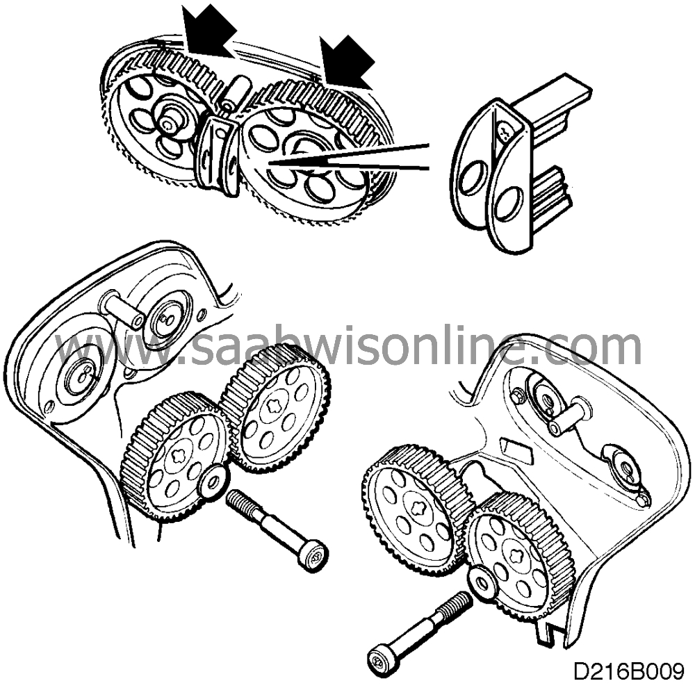
Tightening torque 50 Nm (37 lbf ft) + 60.
|
|
11.
|
Fit the new belt tensioner bracket.
Turning torque 40 Nm (30 lbf ft).
|
|
12.
|
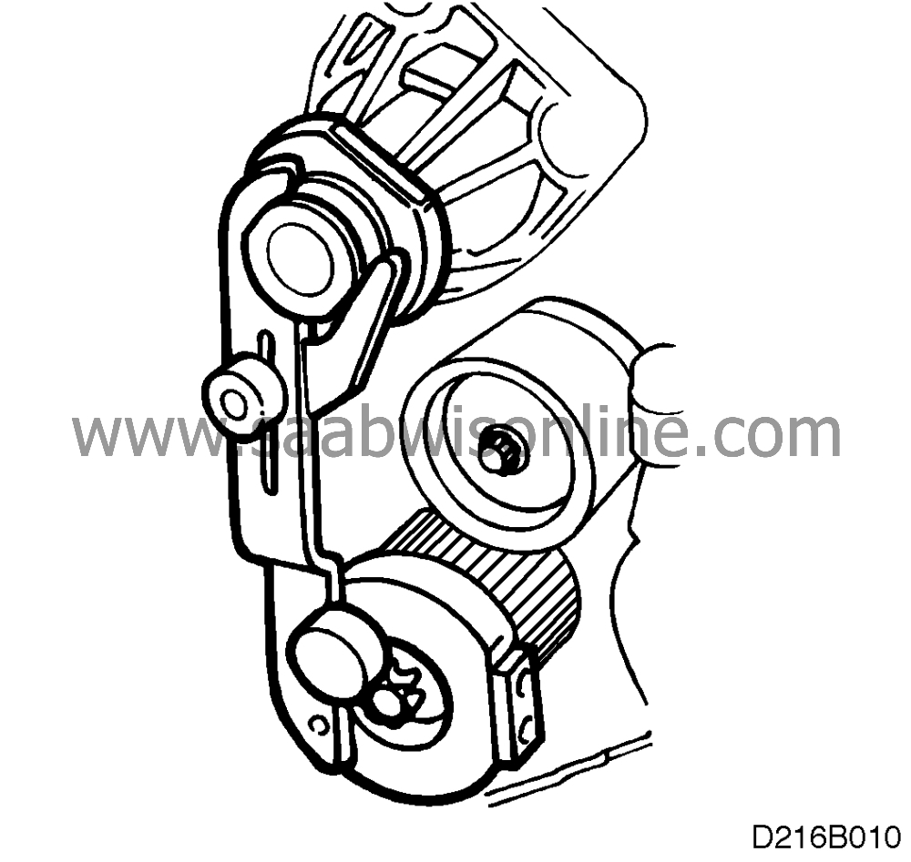
Turn the crankshaft to just before top dead centre and fit locking tool KM-800-10 on the crankshaft. Carefully turn the crankshaft in the engine's direction of rotation until the arm rests against the coolant pump's flange and then remove the tool.
|
|
13.
|
Fit the toothed belt with the arrows pointing in the direction of rotation so that the markings on the belt match the markings on the crankshaft's toothed belt pulley and the camshaft sprockets. Use KM-800-30 to keep the belt in place and adjust the tensioning roller loosely by hand to prevent the belt from jumping off. Adjust anticlockwise.
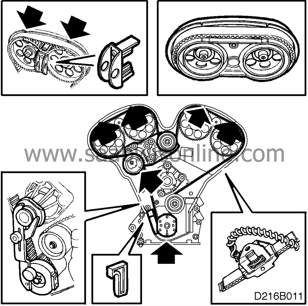
Fit locking tool KM-800-10, place a length of toothed belt in position and use tool 83 93 985 to measure the belt tension.
Loosely tighten the centre bolts of the adjusting rollers. Adjust the lower adjusting roller anticlockwise to a belt tension of 275-300 Nm. Tighten the adjusting roller bolt.
Turning torque 40 Nm (30 lbf ft).
|
Important
|
|
Adjustment of belt tension is only a preparatory measure and must not be used as a check when the belt is finally adjusted.
|
|
|
|
|
14.
|
Adjust the tensioning pulley with an allen wrench until the two marks are aligned. Tighten.
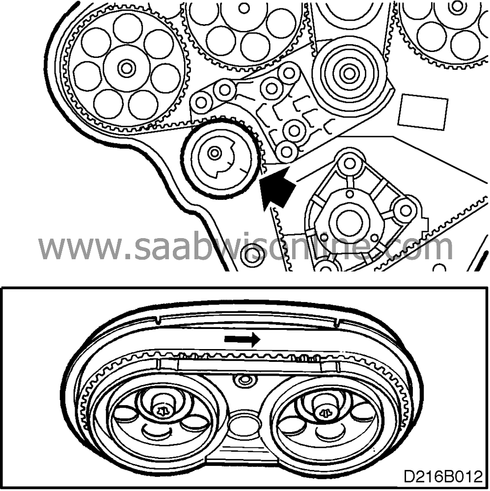
Tightening torque 20 Nm (15 lbf ft).
Remove the locking tool for camshaft sprockets 1 and 2 and fit KM-800-20. The adjust the upper adjusting roller anticlockwise until camshaft sprocket No. 2 moves 1-2 mm clockwise
Turning torque 40 Nm (30 lbf ft).
Remove the upper locking tool.
|
|
15.
|
Turn the crankshaft two revolutions until just before the zero mark and place the locking tool on it. Carefully turn the crankshaft in the direction of engine rotation until the arm rests against the coolant pump's flange and then tighten the arm. Fit tool KM-800-20 on the camshaft sprockets and check that the markings on them are aligned with the markings in the tool and that the edge of the belt is aligned with the edges of the sprockets.
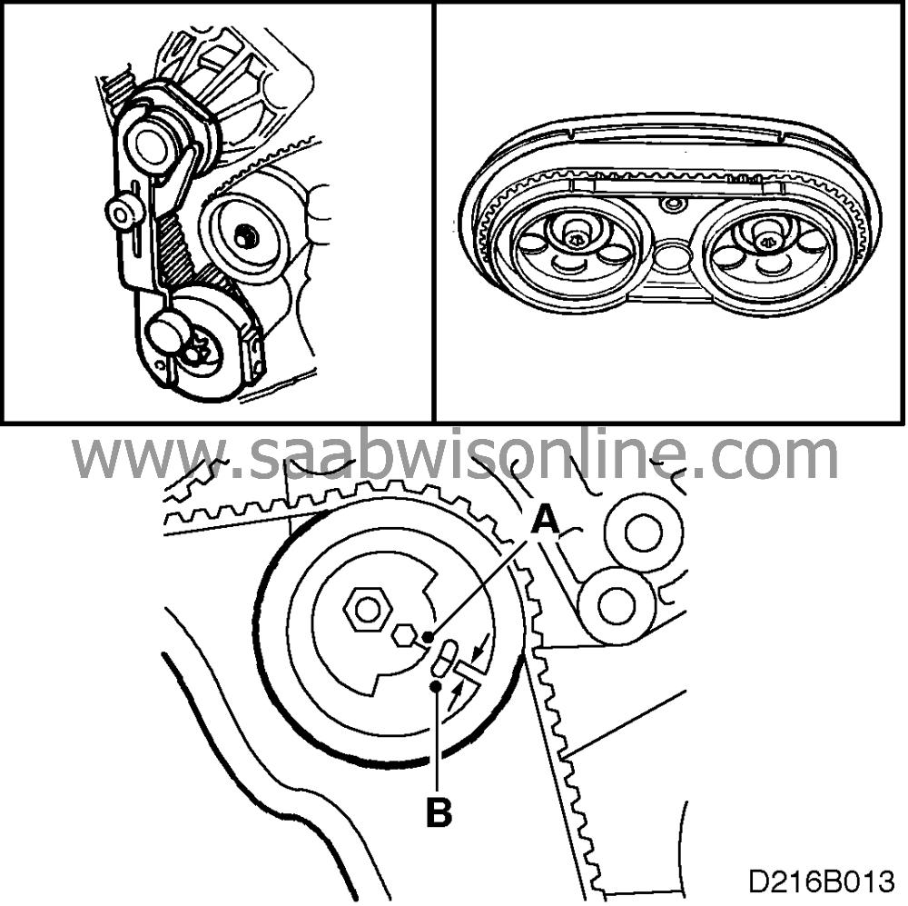
|
Important
|
|
Check that the A marking is about 2 mm above the B marking, see illustration. If the distance is less than this, readjustment will be necessary.
|
|
|
|
|
16.
|
Mount the closed-circuit crankcase ventilation housing and fit the oxygen sensor's connector in its holder. Check that the O-rings are in place in the valve cover and wipe dry. Lubricate with a soap solution and apply silicone, part No. 87 81 841, in the corners by the camshaft bearing caps. Fit the valve cover.
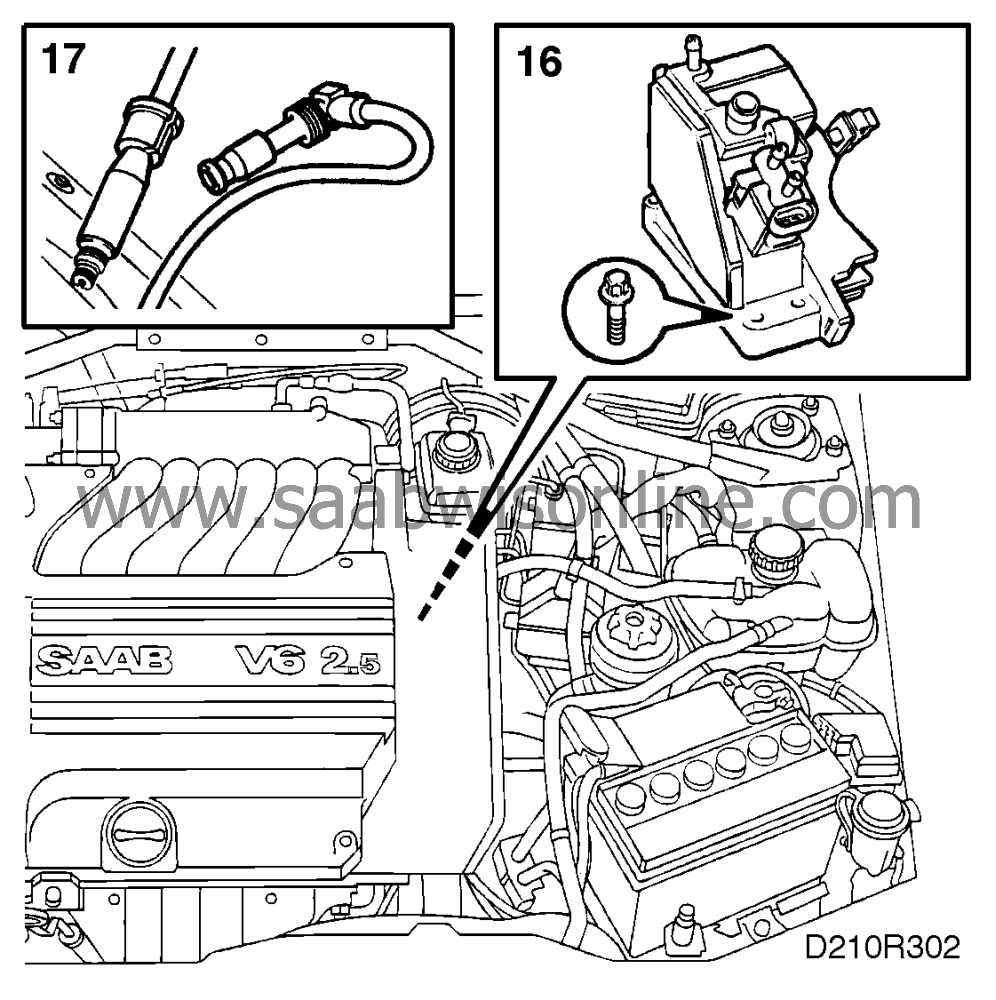
|
|
17.
|
Fit the spark plugs and connect HT leads 1-3-5.
Tightening torque: 25 Nm (18.5 lbf ft).
|
|
18.
|
Fit the crankshaft pulley with the notch pointing towards the lug on the engine (diagonally upwards-forwards)
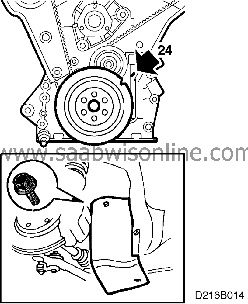
Tightening torque 20 Nm (15 lbf ft).
|
|
19.
|
Fit the cover and right-hand front wheel.
Tightening torques
110 Nm (81 lbf ft)
Lower the car to the floor.
|
|
20.
|
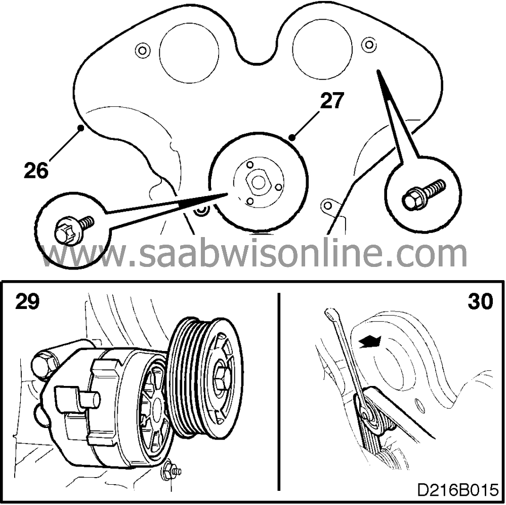
Fit the outer timing cover.
|
|
21.
|
Refit the coolant pump pulley (the engine will have to be pressed to the left in the car, use the engine bracket as a counterstay). Apply locking fluid 74 96 268 to the bolts and tighten the pulley.
Tightening torque 10 Nm (7.5 lbf ft).
|
|
22.
|
Fit the power steering pump pulley.
Turning torque 8 Nm (6 lbf ft).
|
|
23.
|
Fit the belt tensioner.
Turning torque 40 Nm (30 lbf ft).
|
|
24.
|
Relieve the load from the belt tensioner by turning the belt tensioner pulley locking bolt forwards in the car using a 15 mm wrench. Fit the belt on the coolant pump pulley and check the other pulleys. Carefully release the belt tensioner.
|
|
25.
|
Tighten the bolts securing the pulleys.
|
|
26.
|
Fit the coolant bridge with 74 96 284 on the bolts. Refit the coolant hose and electrical connectors.

Turning torque 30 Nm (22 lbf ft).
|
|
27.
|
Use a new gasket and fit the lower section of the intake manifold. Lock the bolts with 74 96 268.

Turning torque 20 Nm (15 lbf ft).
|
|
28.
|
Fit the middle intake manifold using a new gasket and the fuel rail. Remove the protective tape. Lock the bolts with 74 96 268.
Tightening torque 20 Nm (15 lbf ft).
|
|
29.
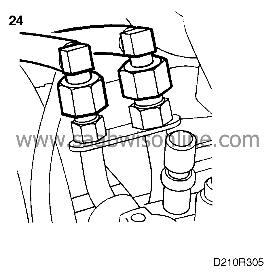
|
Connect the fuel lines.
|
|
30.
|
Fit the intake manifold. First fit:

|
|
|
•
|
the hose to the evaporative (EVAP) emission canister air purging valve
|
|
|
•
|
the coolant hoses to the throttle body
|
|
|
•
|
the TCS throttle body connector
|
|
|
•
|
the IAC valve connector
|
|
|
•
|
the secondary air injection vacuum hose (where fitted).
|
|
|
•
|
the hose to the fuel pressure regulator in front of the butterfly.
Tighten all bolts at the mating surface. Begin with the bolts in the middle and continue alternately towards the ends.
Tightening torque 20 Nm (15 lbf ft).
|
|
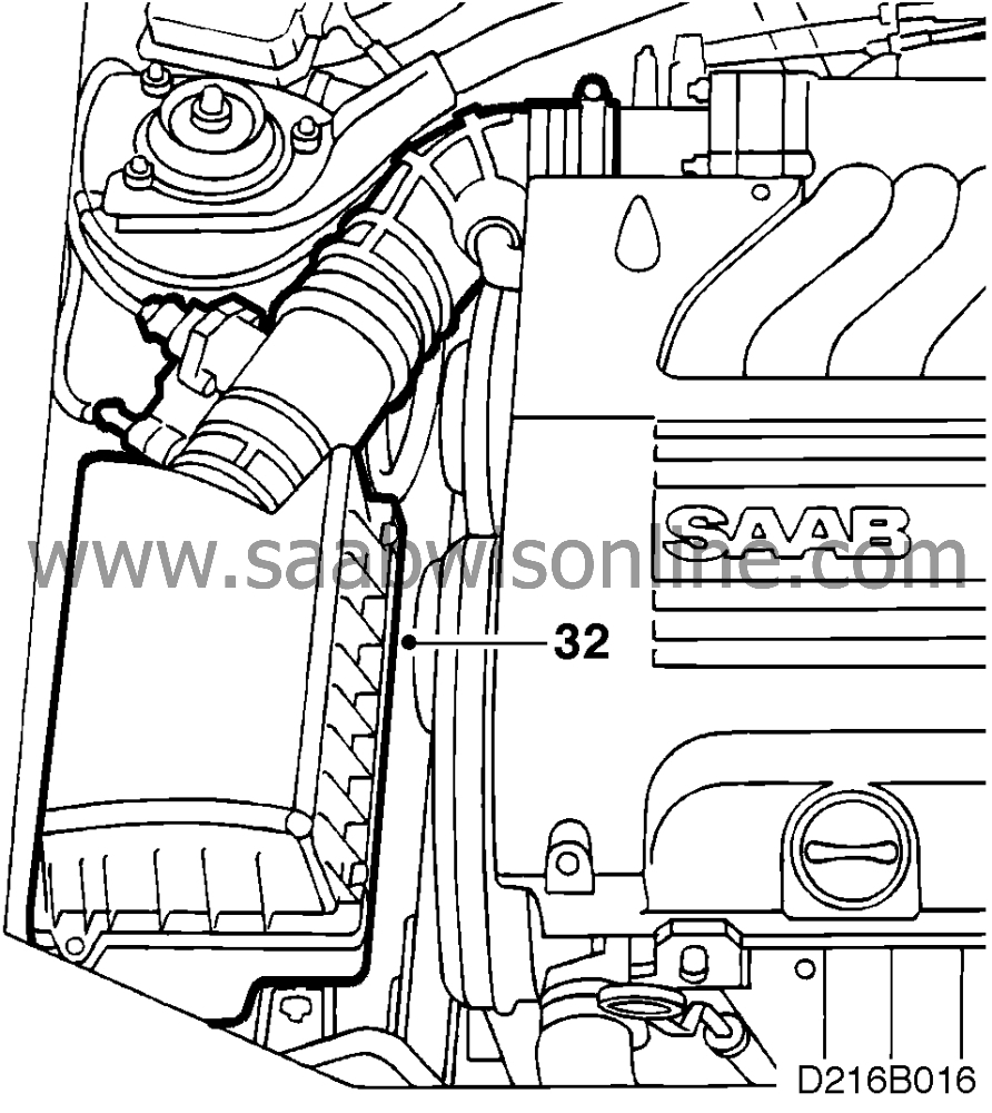
31.
|
Refit the air cleaner complete with hoses.
|
|
32.
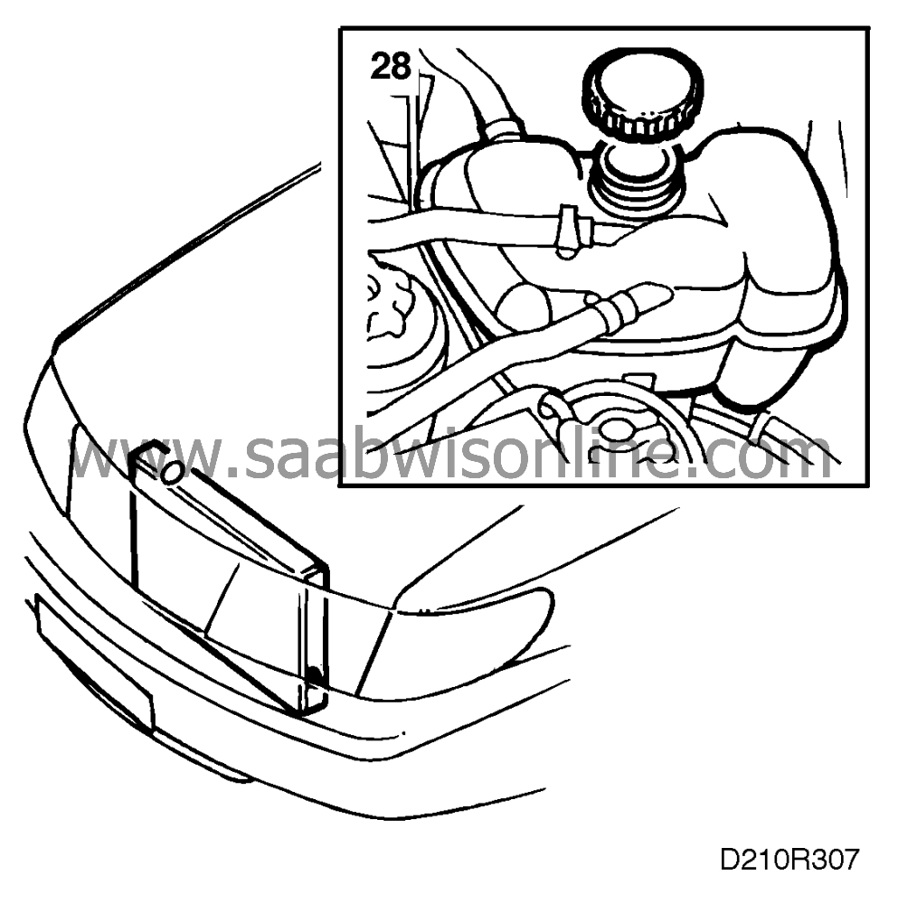
|
Reconnect the negative cable to the battery. Remove the covers protecting the wings.
|
|
33.
|
Check that the radiator's drain plug is tightened, fill up with coolant and check that the system does not leak. Refit the pressure pipe between the charge air cooler and the throttle body and refit the bypass hose (turbo).
|
|
34.
|
Bleed the system as follows:
Fill the system up to the MAX level, fit the pressure cap, start the engine and warm it up, preferably at varying rpm, until the radiator fan starts.
Remove the pressure lid and fill up to MAX again.
Refit the pressure lid and let the engine run at varying speeds until the radiator fan has started a further three times.
Switch off the engine and top up to the MAX level, if necessary.
|
|
35.
|
Drive the car on the road and check all functions.
|


 Warning


