Test values, control moduleconnections
| Test values, control module connections |
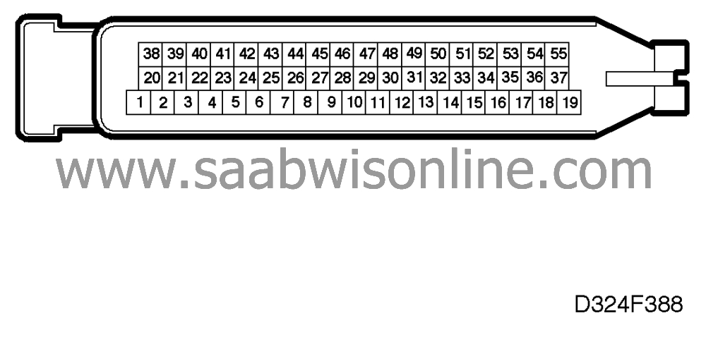
| Some important points to remember: |
| • |
Unless otherwise specified, all
voltage measurements should be made
with all components connected and with the ignition switch in the Drive
position.
|
|
| • |
Readings must be taken with a Breakout Box (BOB) connected between the
control module and the control module connector.
|
|
| • |
Some readings are to be taken with the engine running at idling
speed.
|
|
| • |
Several voltage levels must be regarded as guiding values. Your common
sense should tell you whether a reading is correct or not.
|
|
| • |
If any test reading is obviously wrong, use the wiring diagram to trace
the leads, connectors or components which you consider ought to be
checked more thoroughly.
> = greater than; < = less than; » = approximately equal to; ∼ = alternating current |
|
|
Pin
|
Colour
|
Component/Function
|
Input/Output
|
Test
condition
|
Test
reading
|
Across
|
|
1
|
GN/WH
|
Ignition coil, cyl. 1+4
|
Output
|
Ignition ON
2000 rpm |
Batt+
» 0.2 V |
1 - 14
37 - 1 |
|
2
|
BK
|
Power ground
|
Input
|
Idling
|
< 0.1 V
|
2 - 14
|
|
3
|
WH
|
Fuel pump relay
|
Output
|
Ignition ON
Starter motor cranking/idling Idling |
Batt+
0 Volt |
3 - 14
|
|
4
|
RD/BK
|
IAC valve
|
Output
|
Idling, engine hot
|
»
5-7 V
» 4-6 ms 100 Hz |
37 - 4
|
|
5
|
GN/YE
|
EVAP canister purge valve
|
Output
|
Idling, engine hot
|
»
0.3-0.5 V
15 Hz |
37 - 5
5 - 14 |
|
6
|
Not used
|
|||||
|
7
|
BU/BN
|
Mass air flow sensor
|
Input
|
Idling
2500 rpm Full throttle |
»
0.8 V
» 1.2 V » 3.5 V |
7 - 30
|
|
8
|
YE
|
Camshaft position sensor
|
Input
|
Ignition On, engine turning over
Idling |
0/5 V
» 4.5 V » 7 Hz |
8 - 14
|
|
9
|
PK/BK
|
Wheel speed, FR
|
Input
|
Ignition ON
FR wheel rotating |
0/10 V
|
9 - 14
|
|
10
|
BK
|
Reference ground, oxygen sensor
|
Input
|
Idling
|
< 0.1 V
|
10 - 14
|
|
11
|
GN
|
Knock sensor 1
|
Input
|
4000 rpm
|
»
20 mV∼
|
11 - 14
|
|
12
|
BN/GY
|
Throttle position sensor (power
supply)
|
Output
|
Ignition ON
|
5 V
|
12 - 14
|
|
13
|
GY/WH
|
Diagnostic lead (L)
|
Input/
Output
|
Ignition ON
|
»
5 V
|
13 - 14
|
|
14
|
BK
|
Power ground
|
Input
|
Idling
|
< 0.1 V
|
14 - Batt. neg.
|
|
15
|
OG/BK
|
Injector, cyl. 5
|
Output
|
Idling, engine hot
|
»
0.4 V
» 3 ms » 7 Hz |
37 - 15
|
|
16
|
GN/BN
|
Injector, cyl. 2
|
Output
|
Idling, engine hot
|
»
0.4 V
» 3 ms » 7 Hz |
37 - 16
|
|
17
|
BN/WH
|
Injector, cyl. 1
|
Output
|
Idling, engine hot
|
»
0.4 V
» 3 ms » 7 Hz |
37 - 17
|
|
18
|
PK/WH
|
Batt. voltage +30 (memory)
|
Input
|
Battery OK
|
Batt+
|
18 - 14
|
|
19
|
BK
|
Signal ground
|
Input
|
Idling
|
< 0.1 V
|
19 - 14
|
|
20
|
BU/OG
|
Ignition coil, cyl. 2 + 5
|
Output
|
Ignition ON
2000 rpm |
Batt+
» 0.2 V |
20 - 14
37 - 20 |
|
21
|
YE/GY
|
Ignition coil, cyl. 3 + 6
|
Output
|
Ignition ON
2000 rpm |
Batt+
» 0.2 V |
21 - 14
37 - 21 |
|
22
|
YE/GN
|
CHECK ENGINE (MIL)
|
Output
|
Ignition ON
MIL on Idling MIL out |
Batt+
0 Volt |
37 - 22
|
|
23
|
Not used
|
|||||
|
24
|
BK
|
Power ground
|
Input
|
Idling
|
< 0.1 V
|
24 - 14
|
|
25
|
RD/WH
|
AC relay
|
Output
|
Idling, AC ON
Idling, AC OFF |
Batt+
0 Volt |
37 - 25
|
|
26
|
OG
|
Relay, secondary air injection pump
|
Output
|
Idling, < 60 s after starting
|
Batt+
|
37 - 26
|
|
27
|
YE/GY
|
Batt. voltage +15
|
Input
|
Ignition ON
|
Batt+
|
27 - 14
|
|
28
|
GN
|
Oxygen sensor 1
|
Input
|
Idling, engine hot
|
0-1 V
|
28 - 10
|
|
29
|
GN
|
Knock sensor 2
|
Input
|
4000 rpm
|
»
20 mV∼
|
29 - 14
|
|
30
|
BK
|
Sensor ground
|
Output
|
Idling
|
< 0.1 V
|
30 - 14
|
|
31
|
|
Not used
|
|
|
|
|
|
32
|
|
Not used
|
|
|
|
|
|
33
|
BK/GN
|
Injector, cyl. 6
|
Output
|
Idling, engine hot
|
»
0.4 V
» 3 ms » 7 Hz |
37 - 33
|
|
34
|
GY/OG
|
Injector, cyl. 4
|
Output
|
Idling, engine hot
|
»
0.4 V
» 3 ms » 7 Hz |
37 - 34
|
|
35
|
BK/RD
|
Injector, cyl. 3
|
Output
|
Idling, engine hot
|
»
0.4 V
» 3 ms » 7 Hz |
37 - 35
|
|
36
|
|
Not used
|
|
|
|
|
|
37
|
GN/RD
|
Supply voltage
|
Input
|
Ignition ON
|
Batt+
|
37 - 14
|
|
38
|
VT/WH
|
TCS active
|
Input
|
TCS activated
|
»
6 V
|
38 - 14
|
|
39
|
|
Not used
|
|
|
|
|
|
40
|
GN/GY
|
AC ON/OFF
|
Input
|
Ignition ON
AC ON Ignition ON AC OFF |
Batt+
0 Volt |
40 - 14
|
|
41
|
Not used
|
|||||
|
42
|
BK/WH
|
D/R input
|
Input
|
Ignition ON
R-D-3-2-1 |
Batt+
|
42 - 14
|
|
43
|
GN/RD
|
Output, engine rpm
|
Output
|
Idling
2500 rpm |
»
6.5 V
» 40 Hz » 6.5 V » 125 Hz |
43 - 14
|
|
44
|
GY/GN
|
Intake air temperature sensor
|
Input
|
Ignition ON
air temperature about 25°C
|
»
3.4 V
|
44 - 30
|
|
45
|
RD
|
Coolant temperature sensor
|
Input
|
Ignition ON engine temp. about
90°C
|
»
0.9 V
|
45 - 30
|
|
46
|
BU/GY
|
Main relay
|
Output
|
Ignition ON
Ignition OFF |
0V
Batt+ |
46 - 14
|
|
47
|
GN
|
Oxygen sensor 2
|
Input
|
Idling, engine hot
|
0-1 V
|
47 - 14
|
|
48
|
YE
|
Crankshaft position sensor
|
Input
|
Starter motor cranking
Idling 2500 rpm |
»
2-5 V∼
» 7-10 V∼ » 20 V∼ |
48 - 49
|
|
49
|
BK
|
Crankshaft position sensor
|
Input
|
Starter motor cranking
Idling 2500 rpm |
»
2-5 V∼
» 7-10 V∼ » 20 V∼ |
49 - 48
|
|
50
|
Not used
|
|||||
|
51
|
OG/ WH
|
Shift signal
(torque reduction)
|
Input
|
See diagnostic trouble codes
P1300/P1301
|
|
|
|
52
|
|
Not used
|
|
|
|
|
|
53
|
GY/WH
|
Throttle position sensor
|
Input
|
Ignition ON, idling position
Ignition ON full throttle position |
»
0.5 V
» 4.5 V |
53 - 30
|
|
54
|
GN/OG
|
Throttle position signal to TCS and
AF22
|
Output
|
Ignition ON
Idling 2500 rpm Full throttle |
»
0.25-1 V
100 Hz » 1.2 V 100 Hz » 2.0 V 100 Hz » 12 V 100 Hz |
54 - 14
|
|
55
|
GY/BK
|
Diagnostic lead (K)
|
Input/
Output
|
Ignition ON, ISAT connected
|
»
10 V
|
55 - 14
|
This project is supported by memberships and donations. If you use this site, please consider Joining SCNA and/or making a donation.
Our Friends
