
Measured values, ECM connections
| Measured values, ECM connections |
| Points to remember: |
| • |
The measurements must be
performed using a Breakout Box (BOB) connected between the ECM and the ECM's
connector.
|
|
| • |
Several voltage levels must be regarded as guide values. Use common sense in
assessing whether a measured value is correct or incorrect.
|
|
| • |
If any measured value is incorrect, use the electrical diagram to establish wheich
leads, connectors or components should be checked more closely.
|
|
| • |
All the measured values apply to a warmed-up engine.
|
|
| • |
Unless otherwise stated, the ignition must be switched on
|
|
| • |
Indicated measured values relate to calibrated FLUKE 88/97
|
|
> = greater than ; < = less than ; » = approximately equal to; ∼ = AC voltage
Pins without further comments are not connected. (LP: LOGIC PROBE P=select pulse; p=visible pulses).
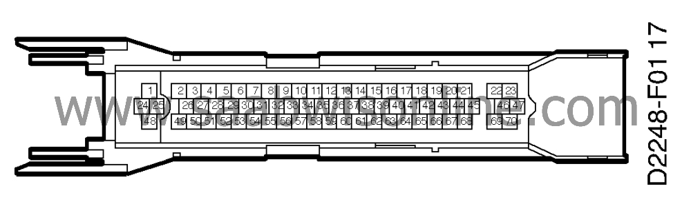
|
pins 1-
2
|
Colour
|
Component
Function
|
In/Out
|
Measuring
conditions
|
Between
|
Measured
value
|
|
1
|
PK/WH
|
+30
|
in
|
Idling speed
|
Batt+ to 1
|
<0.5 V
|
|
2
|
GN/BK
|
Boost pressure control valve
|
out
|
900±50 rpm
|
1 - 2
|
1.3 V
|
|
2 - 25
|
90 Hz 17.5 %% (-) 1.9 ms (-) (LP HI
LO)
|
|||||
|
1000-1500 rpm
|
1 - 2
|
»
0 V
|
||||
|
2 - 25
|
90 Hz 2.0 %% (-) 0.2 ms (-) (LP
LO)
|
|||||
|
3
|
GN/WH
|
Injector 1
|
out
|
900±50 rpm
|
1 - 3
|
0.2 V
|
|
3 - 25
|
7.5 Hz 2.5 ms (-) (
LOp)
|
|||||
|
4
|
BU/WH
|
Injector 2
|
out
|
900±50 rpm
|
1 - 4
|
0.2 V
|
|
4 - 25
|
7.5 Hz 2.5 ms (-) (
LOp)
|
|||||
|
5
|
VT/WH
|
Injector 3
|
out
|
900±50 rpm
|
1 - 5
|
0.2 V
|
|
5 - 25
|
7.5 Hz 2.5 ms (-) (
I
LOp)
|
|||||
|
6
|
GY/WH
|
Injector 4
|
out
|
900±50 rpm
|
1 - 6
|
0.2 V
|
|
6 - 25
|
7.5 Hz 2.5 ms (-) (
HI LOp)
|
|||||
|
7
|
||||||
|
8
|
||||||
|
9
|
OG/BK
|
Trigger 1
|
out
|
900±50 rpm
|
1 - 9
|
1.2 V
|
|
9 - 25
|
7.5 Hz 8.3 %% (-) 11 ms (-) (
LOp)
|
|||||
|
10
|
GN/YE
|
Trigger 2
|
out
|
900±50 rpm
|
1- 10
|
1.2 V
|
|
10 - 25
|
7.5 Hz 8.3 %% (-) 11 ms (-) 11 (
LOp)
|
|||||
|
11
|
BU/RD
|
Trigger 3
|
out
|
900±50 rpm
|
1 - 11
|
1.2 V
|
|
11 - 25
|
7.5 Hz 8.3 %% (-) 11 ms (-) 11 (
LOp)
|
|||||
|
12
|
GY/RD
|
Trigger 4
|
out
|
900±50 rpm
|
1 - 12
|
1.2 V
|
|
12 - 25
|
7.5 Hz 8.3 %% (-) 11 ms (-) 11 (
LOp)
|
|||||
|
13
|
Torque limitation
|
in
|
13 - 25
|
Batt+
|
||
|
Gear-changing
|
13 - 25
|
0 V
|
||||
|
14
|
DRIVE
|
in
|
P, N
|
14 - 25
|
0 V
|
|
|
R, D, 1, 2, 3
|
14 - 25
|
Batt+
|
||||
|
15
|
VT
|
Brake light switch
|
in
|
brake pedal not
depressed
|
15 - 25
|
0 V
|
|
brake pedal depressed
|
15 - 25
|
Batt+
|
||||
|
16
|
||||||
|
17
|
YE/BN
|
Combustion cyl. 1 +
2
|
in
|
900±50 rpm
|
17 - 25
|
1.5 V 15-30 Hz (
HIp)
|
|
18
|
BN/RD
|
Combustion cyl. 3 +
4
|
in
|
900±50 rpm
|
18 - 25
|
1.5 V 15-30 Hz (
HIp)
|
|
19
|
||||||
|
20
|
PK
|
Pressure signal
|
out
|
|
20 - 67
|
1.0 V *)
|
|
21
|
YE/GY
|
Purge valve
Diagnosis
|
in
|
ISAT activates purge valve in Trionic
(EVAP)
|
21 - 25
|
6-7 V 8 Hz 50 %% (-) 60 ms (-) (HIp
LOp)
|
|
22
|
BU/BN
|
Pressure sensor
|
in
|
|
22 - 67
|
100 kPa= 1.9 V see also technical
data
|
|
23
|
GN
|
Oxygen sensor
|
in
|
900±50 rpm and warmed-up
engine
|
23 - 47
|
0.1-0.9 V
|
|
24
|
BK
|
Main ground
|
in
|
900±50 rpm
|
24 - Batt-
|
<0.1 V
|
|
25
|
BK
|
Main ground
|
in
|
900±50 rpm
|
25 - Batt-
|
<0.1 V
|
|
26
|
BU
|
Boost pressure control valve
|
out
|
900±50 rpm
|
1 - 26
|
0 V
|
|
1000-1500 rpm
|
1 - 26
|
2.3 V
|
||||
|
1000-1500 rpm
|
1 - 26
|
90 Hz 17.5 %% (-) 1.9 ms (-) (LP P HI
LO)
|
||||
|
27
|
YE/GY
|
Evaporative emission canister purge
valve
|
out
|
ISAT activates purge valve in Trionic
(EVAP)
|
21 - 25
|
6-7 V 8 Hz 50 %% (-) 60 ms (-) (LP HI
LO)
|
|
28
|
|
|
|
|
|
|
|
29
|
|
|
|
|
|
|
|
30
|
|
|
|
|
|
|
|
31
|
BU/GY
|
MAIN RELAY
|
out
|
31 - 25
|
Batt+
|
|
|
ISAT activates IAC valve
|
32 - 25
|
0 V
|
||||
|
32
|
YE/GN
|
CHECK ENGINE
|
out
|
32 - 25
|
<0.5 V
|
|
|
After 3 seconds
|
32 - 25
|
Batt+
|
||||
|
33
|
GY/BK
|
Diagnosis
|
In/Out
|
ISAT not connected
|
33 - 25
|
»
6.5 V
|
|
ISAT connected
|
33 - 25
|
Batt+
|
||||
|
34
|
||||||
|
35
|
YE/BK
|
Engine load signal AC and all consumers switched
off
|
out
|
900±50 rpm
|
35 - 25
|
»
35 mV 30 Hz
»
25 µs (+)
|
|
2500 rpm
|
35 - 25
|
»
65 mV 83 Hz
»
40µs (+) (LP
P HI
)
|
||||
|
36
|
BU/GN
|
Cruise control
|
in
|
36 - 25
|
Batt+
|
|
|
Activate diagnostic mode CC, press
SET/RES
|
36 - 25
|
0 V
|
||||
|
37
|
||||||
|
38
|
||||||
|
39
|
PK/BK
|
Speed signal
|
in
|
Rotate front right wheel 1/2
rev/second
|
39 - 25
|
5 V **) 15 Hz 50 %% (HIp
LOp)
|
|
40
|
|
|
|
|
|
|
|
41
|
YE
|
Crankshaft position
sensor
|
in
|
900±50 rpm
|
41 - 67
|
7-10 V∼
»
870 Hz (LP HI
LO)
|
|
42
|
BN/WH
|
Throttle position sensor
|
out
|
|
42 - 67
|
5 V
|
|
43
|
GY
|
Pressure sensor
|
out
|
|
43 - 67
|
5 V
|
|
44
|
OG
|
Knocking signal
|
in
|
900±50 rpm
|
44 - 25
|
50-100 mV∼ (LP P LO)
|
|
45
|
GN/BN
|
Throttle position sensor
|
in
|
|
45 - 67
|
idling =0.5 V see also technical
data
|
|
46
|
WH/BK
|
Intake air temperature
sensor
|
in
|
|
46 - 67
|
40°C=1.5 V see also technical
data
|
|
47
|
BK
|
Oxygen sensor, reference
ground
|
in
|
900±50 rpm
|
25 - 47
|
<0.05 V
|
|
48
|
PK/WH
|
+30
|
|
900±50 rpm
|
Batt+ - 48
|
<0.5 V
|
|
49
|
BU/VT
|
Idle air control valve
|
out
|
900±50 rpm
|
1 - 49
|
3.5 - 5.5 V
|
|
AC and all power consumers switched
off
|
49 - 25
|
500 Hz 25-45 %% 0.5-0.9 ms (LP HI
LO)
|
||||
|
50
|
BK/WH
|
Oxygen sensor, preheating
|
out
|
900±50 rpm
|
50 - 25
|
»
0.3 V
|
|
remove fuse No. 38
|
50 - 25
|
0 V
|
||||
|
51
|
||||||
|
52
|
||||||
|
53
|
||||||
|
54
|
RD/WH
|
AC out
|
out
|
ISAT activates AC in
Trionic
|
54 - 25
|
Batt+/<0.5 V
|
|
55
|
BU/YE
|
SHIFT UP
|
out
|
|
55 - 25
|
<0.5 V
|
|
56
|
WH
|
FUEL PUMP RELAY
|
out
|
56 - 25
|
Batt+
|
|
|
|
ISAT activates oxygen sensor
preheating in Trionic
|
56 - 25
|
0 V
|
|||
|
57
|
GN/OG
|
Throttle position signal
|
out
|
900±50 rpm
|
57 - 25
|
»
1 V 100 Hz 9 %% (+) 0.9 ms (+)
(LP HI
LO)
|
|
58
|
GN/RD
|
Engine speed signal
|
out
|
900±50 rpm
|
58 - 25
|
»
0.5 V 30 Hz (LP HI
)
|
|
59
|
GN/GY
|
AC in
|
in
|
ISAT activates AC in ICE, ON
|
59 - 25
|
Batt+
|
|
ISAT activates AC in ICE,
OFF
|
59 - 25
|
0 V
|
||||
|
60
|
YE/GY
|
+15
|
in
|
Batt+ -60
|
<0.5 V
|
|
|
61
|
|
|
|
|
|
|
|
62
|
|
Production only
|
|
|
|
|
|
63
|
|
Production only
|
|
|
|
|
|
64
|
|
|
|
|
|
|
|
65
|
|
Production only
|
|
|
|
|
|
66
|
BK
|
Reference ground, coolant temperature
sensor
|
in
|
|
66 - 25
|
<0.05 V
|
|
67
|
BK
|
Sensor ground
|
out
|
|
67 - 25
|
<0.05 V
|
|
68
|
YE/WH
|
Engine coolant temperature
sensor
|
in
|
|
68 - 66
|
90°C = 0.41 V see also technical
data
|
|
69
|
|
|
|
|
|
|
|
70
|
|
|
|
|
|
|
*) slightly lower value may be obtained when measuring at high altitude'
**) with car stationary: 0 V or approx. Batt+'
This project is supported by memberships and donations. If you use this site, please consider Joining SCNA and/or making a donation.
Our Friends