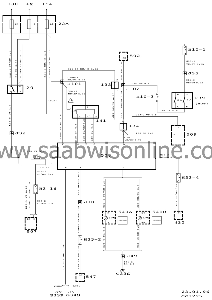
Wiring diagram, cruisecontrol
| Wiring diagram, cruise control |
| Locations of components |
|
22A
|
Fuse holder in the dashboard
|
|
29
|
Brake lights switch on the pedal assembly
|
|
30
|
Brake light bulbs, right-hand and left-hand rear light
clusters
|
|
47U
|
CRUISE indicator lamp in main instrument display
|
|
76
|
Switch, idling speed increase, in selector lever position sensor
239 on the transmission.
|
|
133
|
Clutch switch, Cruise Control, on the clutch pedal
|
|
134
|
Brake pedal switch, on the brake pedal
|
|
141
|
Cruise Control switch, on the lights switch, on the left-hand side
of the steering column
|
|
239
|
Selector lever position sensor, on the transmission
|
|
430
|
Trionic control module, in the cabin, below the right-hand A
pillar
|
|
500
|
ICE control module, on top of relay holder 22B, under the
dashboard adjacent to the steering wheel
|
|
502
|
TCM control module, on the bulkhead partition, behind the glove
box
|
|
507
|
TCS control module, under the right-hand front
seat
|
|
508
|
Cruise Control system control module, on a bracket in the false
bulkhead space, in the engine bay on the right-hand side
|
|
540
|
Main instrument display panel on the dashboard
|
|
540A
|
Main instrument display 1, without rev counter (tachometer), on
the dashboard
|
|
540B
|
Main instrument display 2, with rev counter (tachometer), on the
dashboard
|
|
547
|
ABS control module, on the brake unit in the engine bay
|
|
|
10-pin connectors
|
|
H10-1
|
On a bracket behind the battery in the engine bay
|
|
H10-3
|
On a bracket behind the battery in the engine bay
|
|
|
33-pin connectors
|
|
H33-1
|
Blue 33-pin connector on a bracket below the left-hand A
pillar
|
|
H33-2
|
Black 33-pin connector on a bracket below the left-hand A
pillar
|
|
H33-4
|
On a bracket on the bulkhead partition behind the glove box
|
|
G3
|
Grounding point in the luggage compartment on the left-hand
side
|
|
G33P
|
Power ground on a bracket below the left-hand A
pillar
|
|
G33S
|
Signal ground on a bracket below the left-hand A
pillar
|


