B1720
Symptom: The fuel gauge shows empty. The low fuel warning lamp lights up. Some of
the trip computer's functions are affected.
Fuel level transmitter signal faulty
Fault symptoms
The fuel gauge shows empty. The low fuel warning lamp lights up. Some of
the trip computer's functions are affected.
|
1.
|
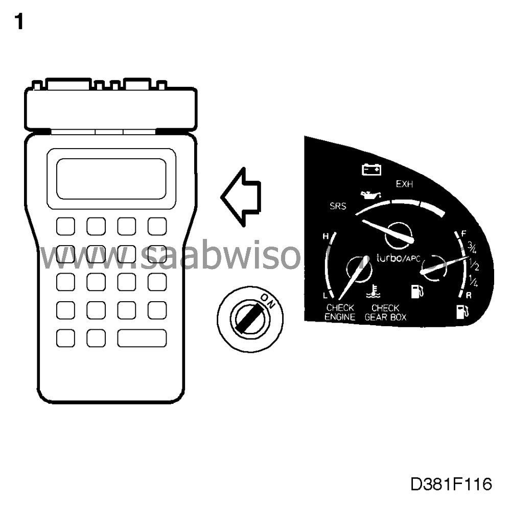
Connect the Scan Tool and
select "READ VALUES" followed by "TANK CONTENTS".
|
|
2.
|
If the fuel level transmitter signal is OK, the reading shown on the Scan
Tool's display should correspond to the contents of the fuel tank. If this is the case,
continue with point 7.
|
|
3.
|
If the display shows tank contents = 0, the fuel level transmitter signal
sent to the main instrument display panel is faulty. In this case, continue by checking the fuel
level transmitter, point 4.
|
|
4.
|
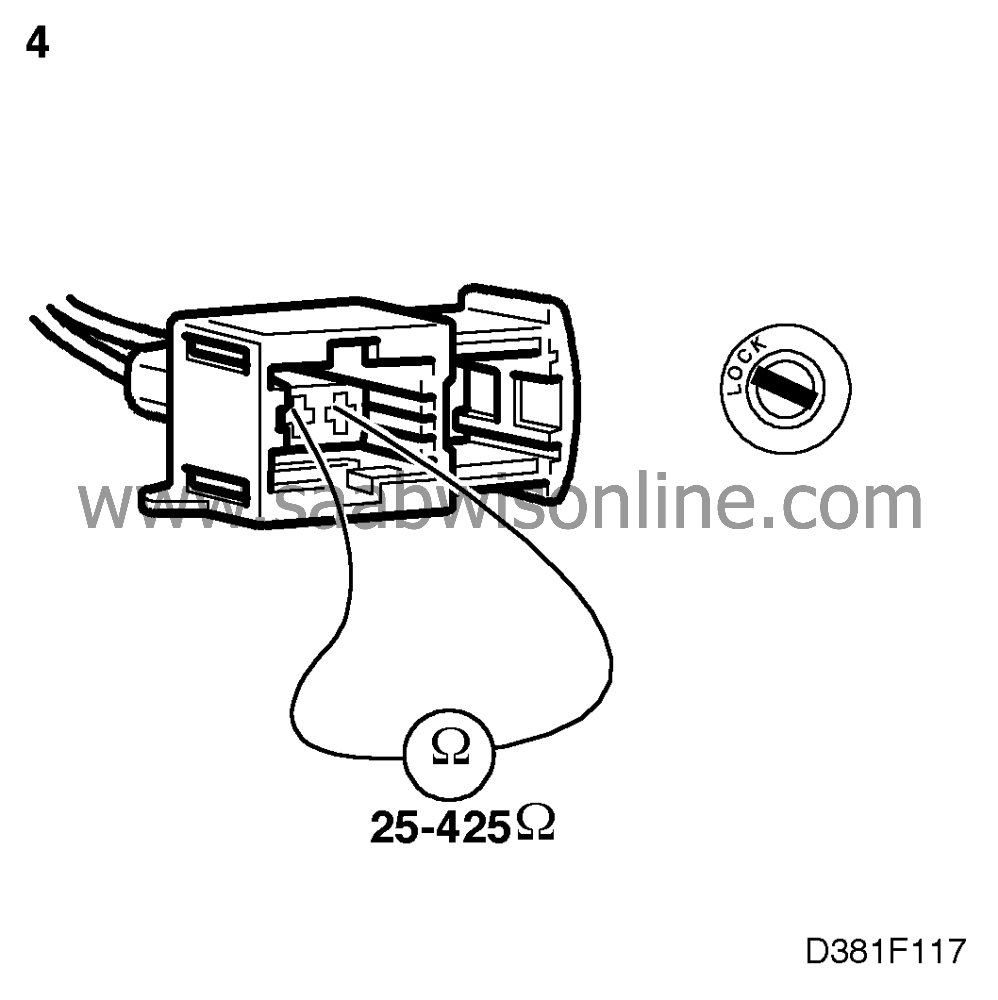
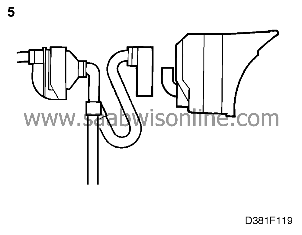
Unplug the fuel level transmitter's connector, which is located under a
cover under the rear seat, and take a resistance reading across the pins. The correct
resistance is between 50 and 390 ohms.
If the resistance is outside this range, the transmitter or its connecting lead is at fault.
Check and take the necessary action.
|
|
5.
|
If the resistance reading is OK, the fault is probably in the wiring between the fuel
level transmitter and the main instrument display panel.
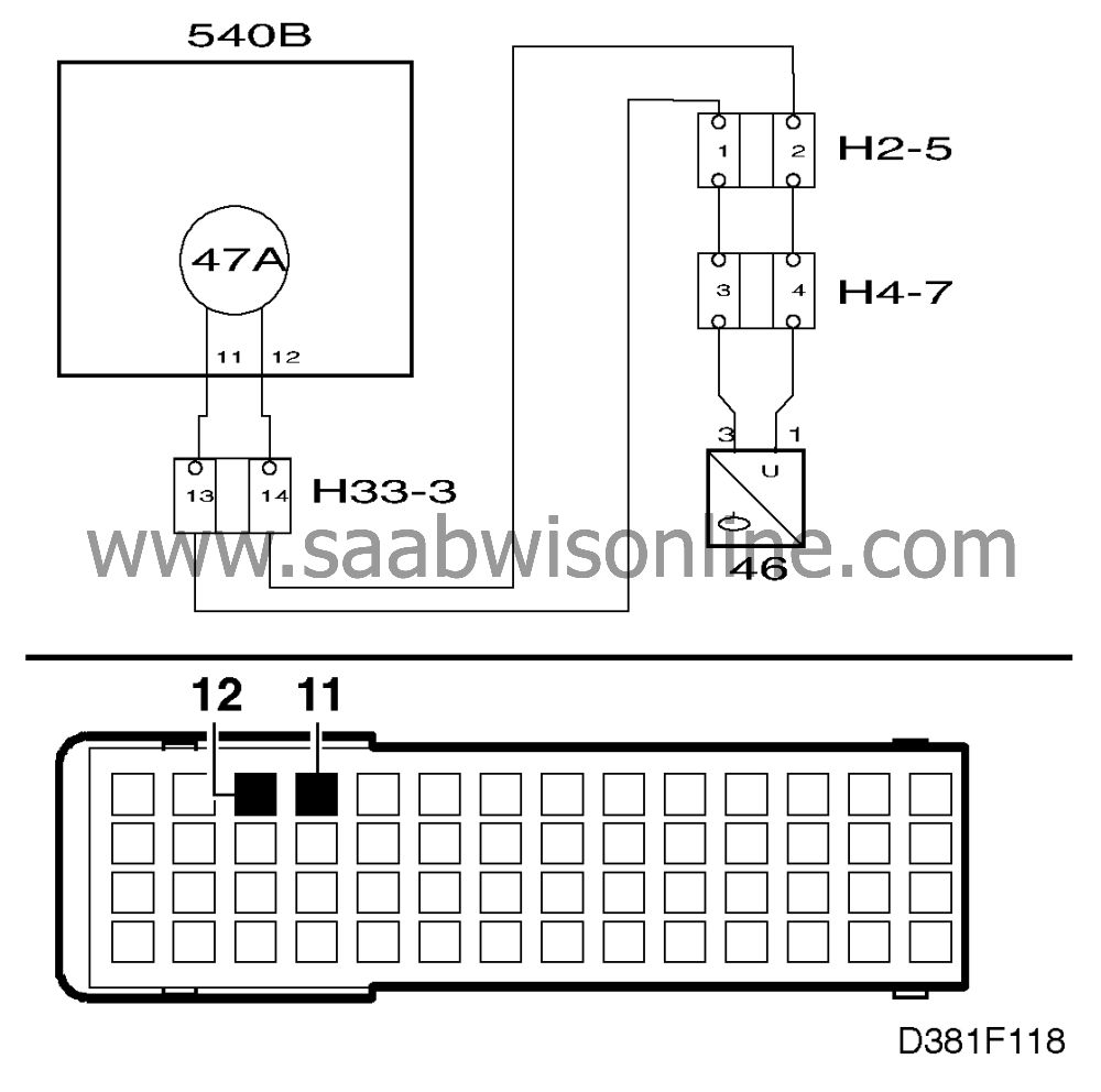
To check this, connect a BOB to the main instrument display panel's 56-pin
connector. The main instrument display panel should not be connected.
|
|
6.
|
Plug in the fuel level transmitter's connector again. Take a reading across
pins 11 and 12 on the BOB to check for continuity/shorting.

The correct resistance across the pins is between 50 and 390 ohms. If this is the case,
continue with point 7. If the reading obtained is outside this resistance range the wiring is
faulty. Investigate the cause and rectify.
|
|
7.
|
Disconnect the BOB and connect the main instrument display panel. Clear the
trouble code and see whether it recurs. If it does not recur, the fault could have been in one of
the connectors.
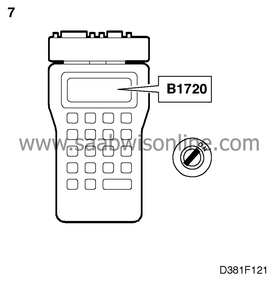
If the trouble code recurs, there may be an open circuit between the connector and the
processor in the main instrument display panel's control module. Continue fault
diagnosis as described on
 .
.
|


