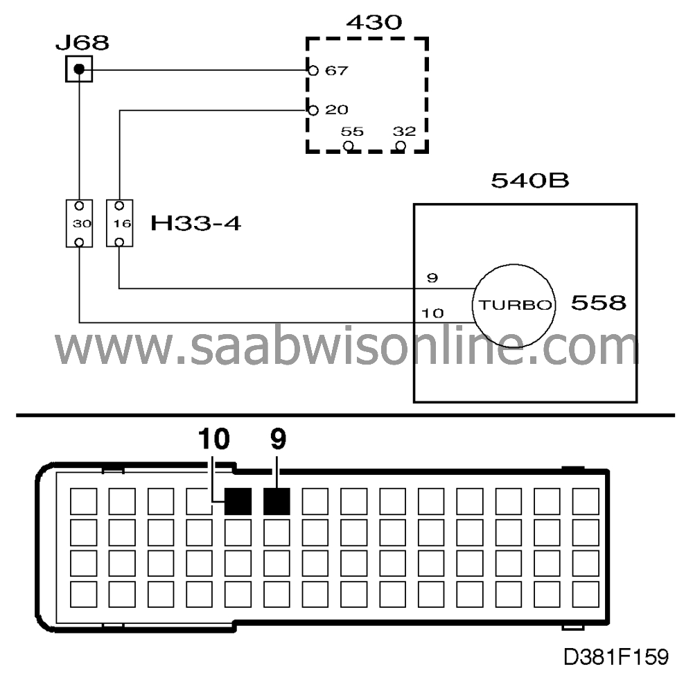
Turbo pressure gauge (turbo/APC),(MIU 2)
|
|
Turbo pressure gauge (turbo/APC),
(MIU 2)
|
The turbo pressure gauge needle stands still at zero or maximum.
|
1.
|
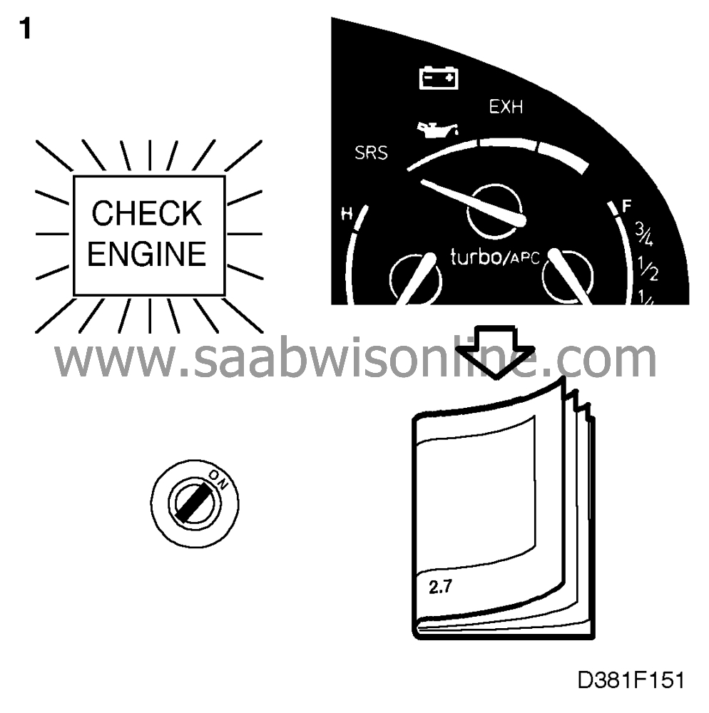
If the CHECK ENGINE lamp
(MIL) lights up or the turbo/APC gauge needle indicates maximum pressure, continue
fault diagnosis as described in Service Manual 2:7 "TRIONIC Engine Management System"
 . If this is not the case, continue with point 2.
|
|
2.
|
Connect the Scan Tool and select "READ VALUES" followed by "TURBO
PRESSURE".
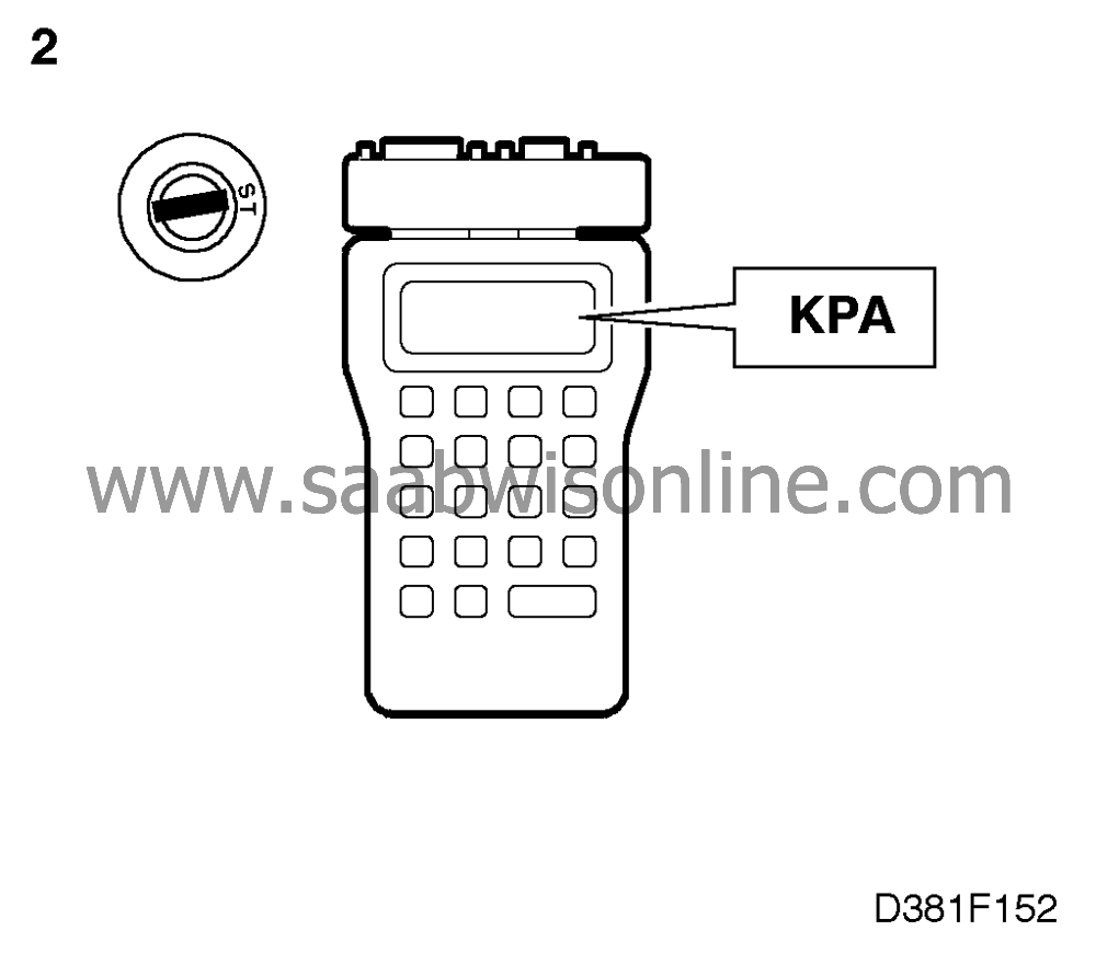
Start the engine.
|
|
3.
|
If the system is in proper working order, the turbo pressure on the Scan Tool
display should vary with different engine rpm and loads.

|
|
4.
|
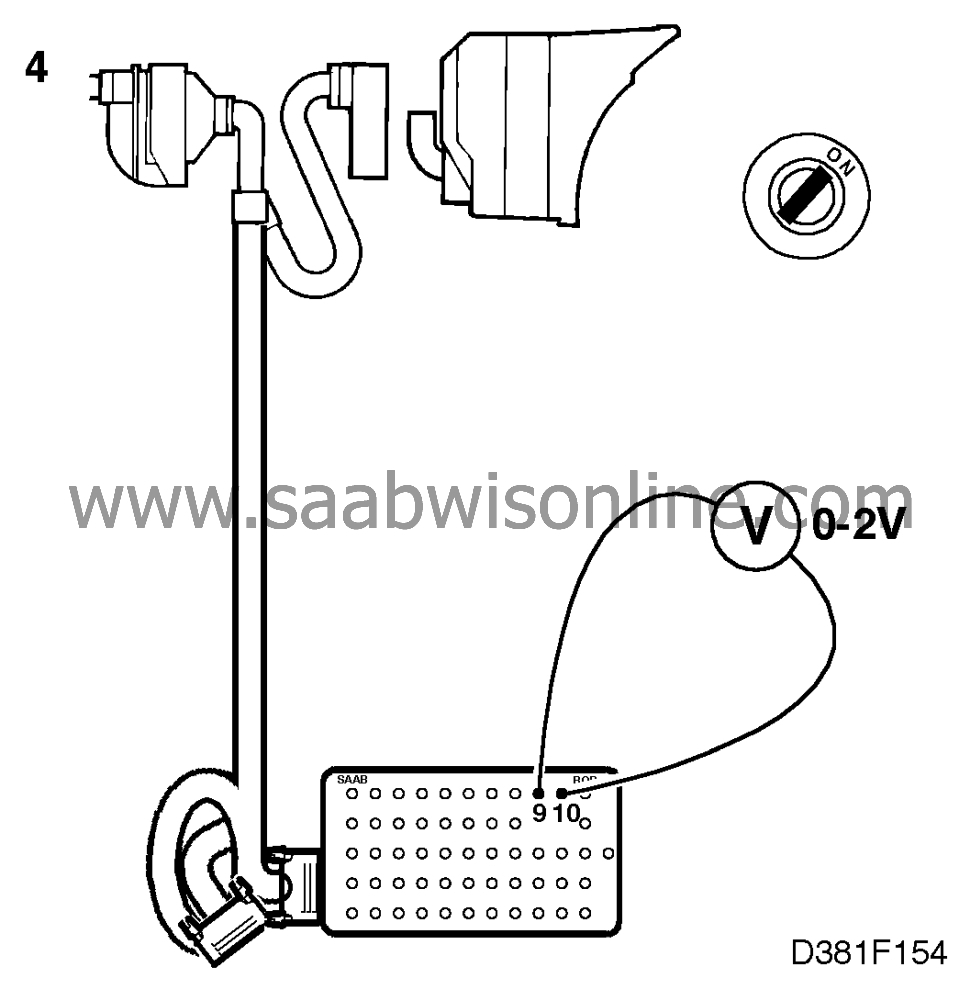
If a signal is present, continue with point 8. If no signal is present, check the input
signal to the main instrument display panel by connecting a BOB to the 56-pin connector
behind the main instrument display panel (which should not be connected). Connect a
voltmeter to pins 9 and 10. Start the engine and check whether a reading is obtained. If
correct, the reading should be between 0 and 2 V.
|
|
5.
|
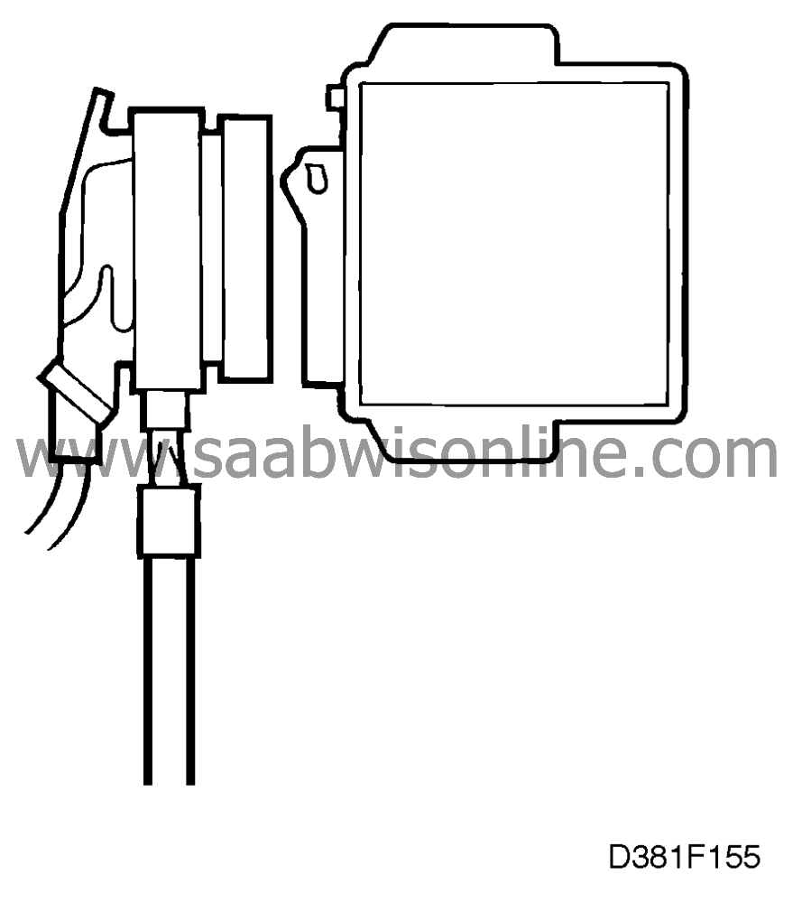
If no reading is obtained, check the wiring by connecting another BOB to the
TRIONIC control module's connector. The main instrument display panel and the
TRIONIC control module should not be connected.
|
|
6.
|
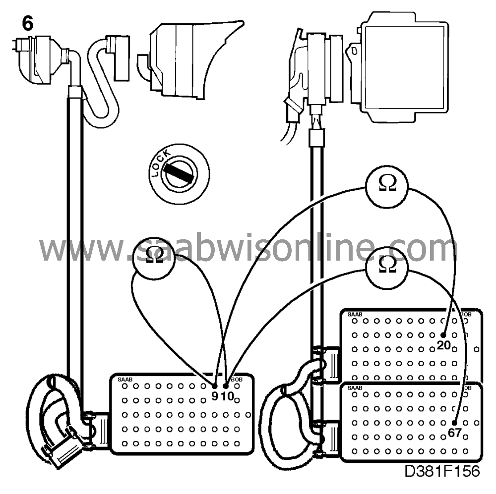
Check the wiring for an open circuit (< 1 Ohm) or short circuit (OL) by taking a
reading across pins 9 and 10 on the BOB connected to the main instrument display panel and
pins 20 and 67 on the other BOB. Take appropriate action in regard to any faults in the wiring.
|
|
7.
|
Connect the Scan Tool and select "TEST FUNCTIONS" followed by "TURBO
GAUGE TEST".
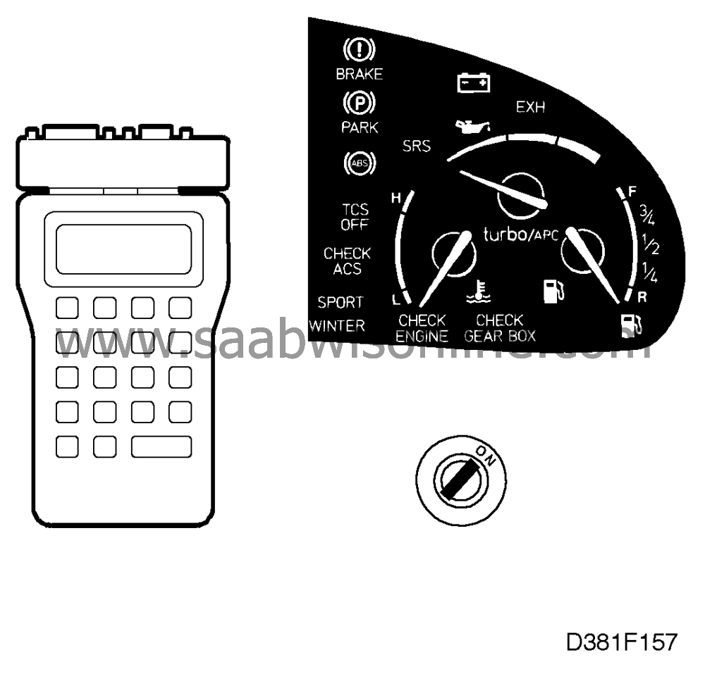
If in proper working order the needle of the turbo/APC gauge should move from left
to right across the scale and back again.
If the turbo/APC gauge does not work, it could be due to an open circuit in the
connection between the processor card and the intermediate part of the main instrument
display panel.
Remove the main instrument display panel's rear section complete with
processor card and check that all leads connected to the connector marked CN3 are securely
located.
If any lead has worked loose or is broken, continue on
 .
.
If the leads connected to the connector are all OK, the fault is probably in the
intermediate part with the indicating instruments. Continue on
 .
.
|
|
8.
|
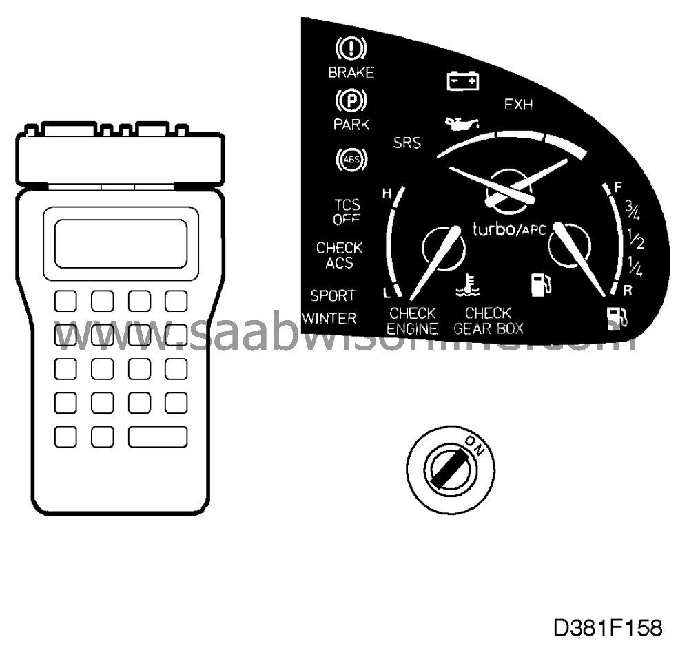
Connect the Scan Tool and select "TEST FUNCTIONS" followed by "TURBO
GAUGE TEST". If in proper working order the needle of the turbo/APC gauge should
move from left to right across the scale and back again. If the turbo/APC gauge works,
there is probably an open circuit between the connector and the processor on the processor
card in the main instrument display panel.
Continue on
 .
.
|


