Symbols used in the wiring diagrams
| Symbols used in the wiring diagrams |
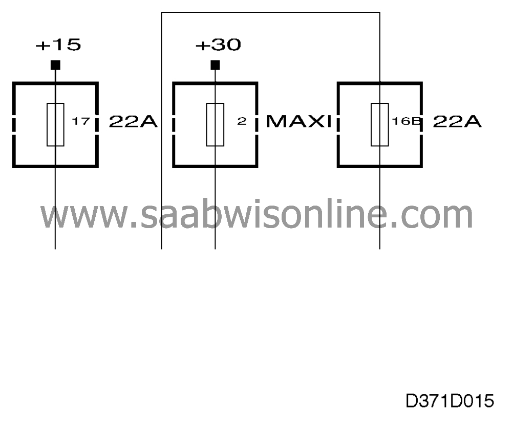
The power supply to each fuse is illustrated separately in the system group for the positive supply in which the main fuse box, ignition switch, etc. are covered.
Example:
The supply to a fuse comes from the +30 terminal block and can be seen up to the fuse in question in the section "Voltage +30"
| Grounding points |

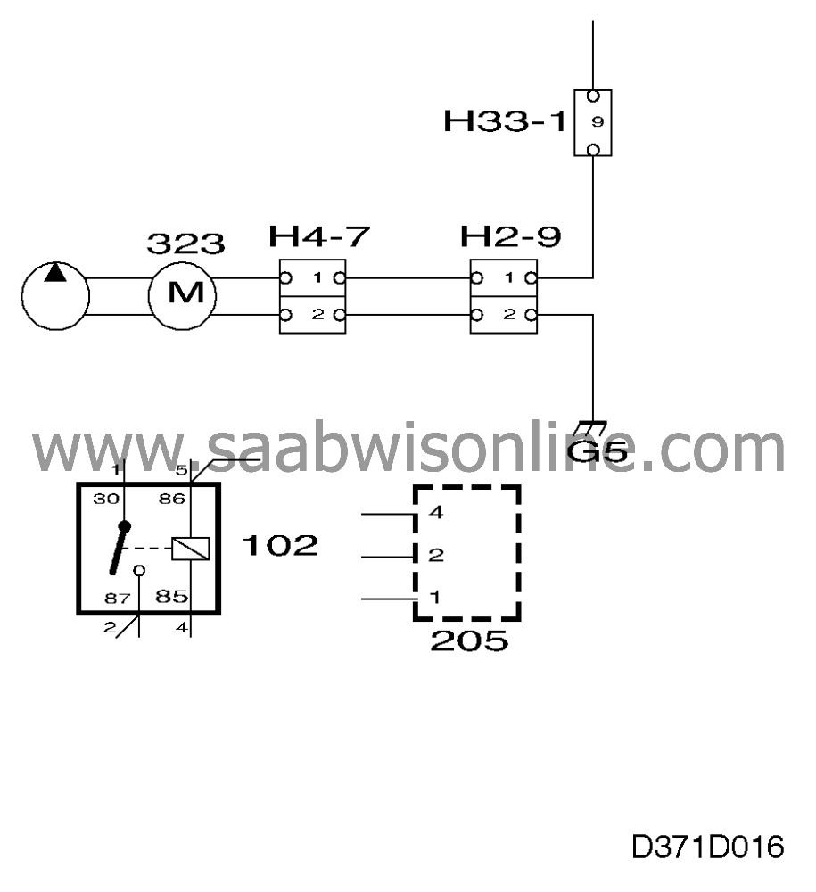
Most of the grounding points in the car have a component number comprising a letter and a number, e.g. G2 or G29. The location of the grounding points can be found in the section "Grounding points".
| Switches, relays and components |
Switches and relays are drawn in a neutral or inactive state respectively unless otherwise stated. The component is shown in full if the box around it is drawn with an unbroken line.
When the box around the component is drawn with a broken line, only part of the component is shown.
| Crimped connections |

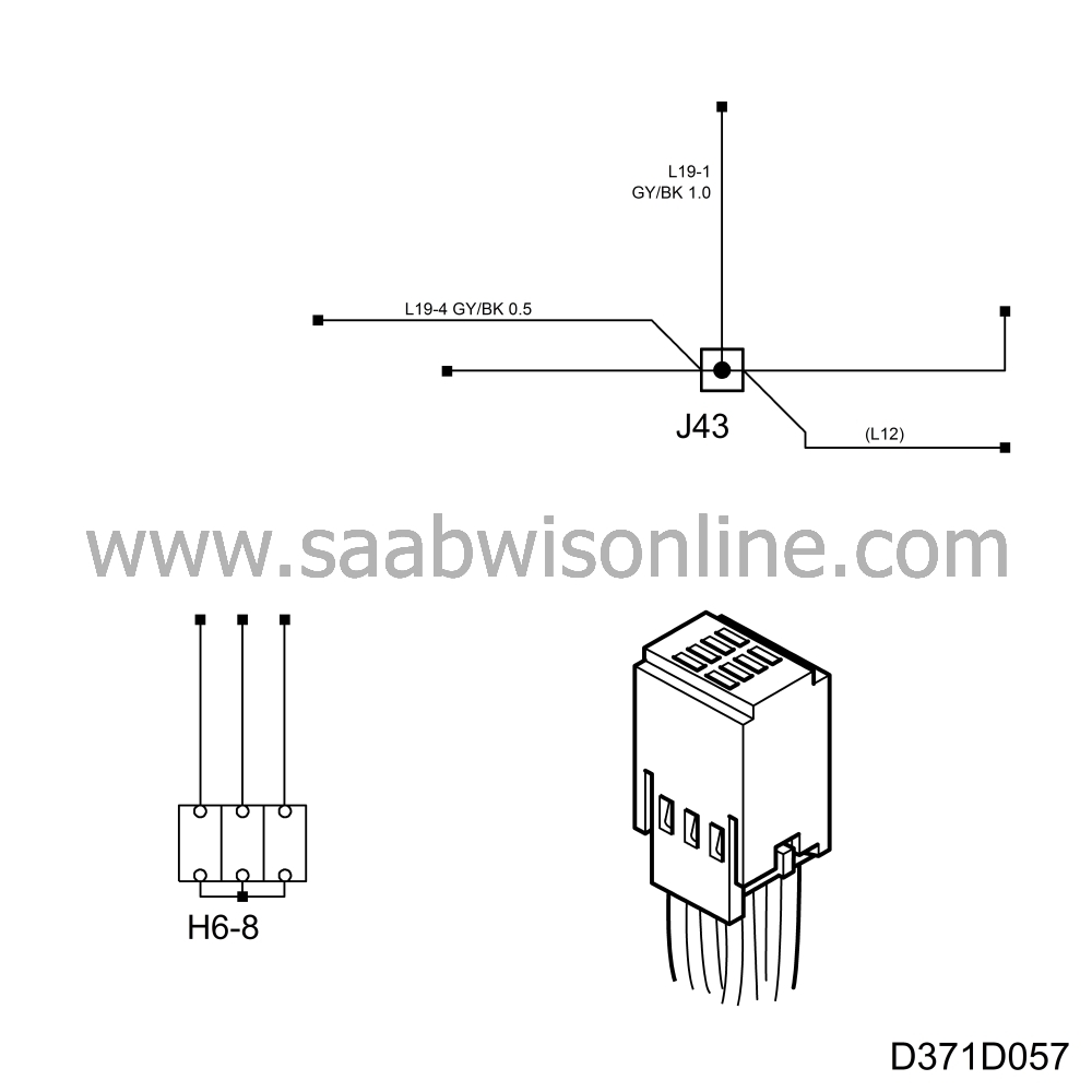
To reduce the number of connectors used in the car, several crimped connections are incorporated in the wiring. They occur as fixed wiring connections and also as connectors. The number of pins in a connector can vary depending on the market and car variant. The max. variant is always shown on the diagram. There is no pin numbering on the connectors.
The way in which they are drawn on the wiring diagrams can be seen adjacent.


