P0705
Symptom: CHECK GEARBOX indicator lamp on.The system's emergency operation program has been activated.
Gear selector position sensor, control module inputs faulty or absent. Shift-lock relay faulty
Fault symptoms
CHECK GEARBOX indicator lamp on.
The system's emergency operation program has been activated.
Conditions
Non-permitted combination of gear selector position sensor contact functions or shift-lock relay faulty.
Diagnostic help
|
•
|
The gear selector position sensor contacts can be read with the diagnostic tool. Select "READ ON/OFF". Select "GSP SENSOR". The diagnostic tool will display the status of all the contacts, ON or OFF.
|
|
•
|
The function of the gear selector position sensor can be read with the diagnostic tool. The contacts are decoded and the current gear position will be displayed. Select "READ FUNCTIONS". Select "SELECT.LEVER POS".
|
Check the wiring
Intermittent faults may occur as a result of temporary short circuits and breaks in the wiring. Jiggle the leads at several places and in different directions to reveal any faults in the wiring harness, including connectors. Observe the multimeter, test lamp or ISAT scan tool while carrying out this check.
Diagnostic procedure
1 Check the gear selector position sensor's outputs
|
-
|
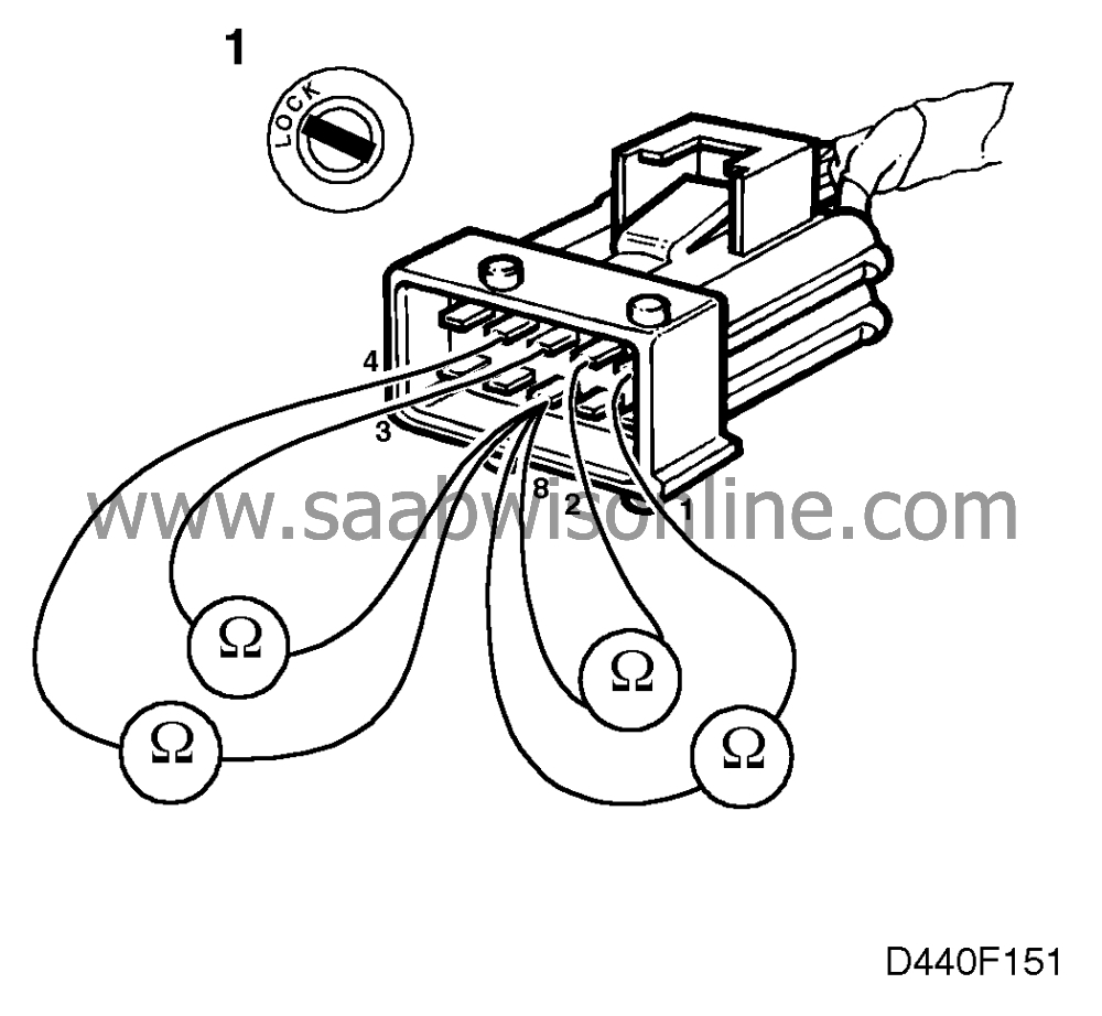
Unplug connector H10-1 (10-pin connector, located behind the battery).
|
|
-
|
Connect an ohmmeter between the relevant pin as indicated in the table (H10-1, male connector) and pin 8. Check the resistance in respect of all selector lever positions (P, R, N, D, 3, 2, 1), see table.
|
Resistance across connector pins
|
1- 8
|
2- 8
|
3- 8
|
4-8
|
P
|
<5 Ohm
|
OL
|
OL
|
<5 Ohm
|
R
|
<5 Ohm
|
<5 Ohm
|
OL
|
OL
|
N
|
OL
|
<5 Ohm
|
OL
|
<5 Ohm
|
D
|
OL
|
<5 Ohm
|
<5 Ohm
|
OL
|
3
|
<5 Ohm
|
<5 Ohm
|
<5 Ohm
|
<5 Ohm
|
2
|
<5 Ohm
|
OL
|
<5 Ohm
|
OL
|
1
|
OL
|
OL
|
<5 Ohm
|
<5 Ohm
|
Are correct resistance readings obtained?
Continue with step 3.
Continue with step 2.
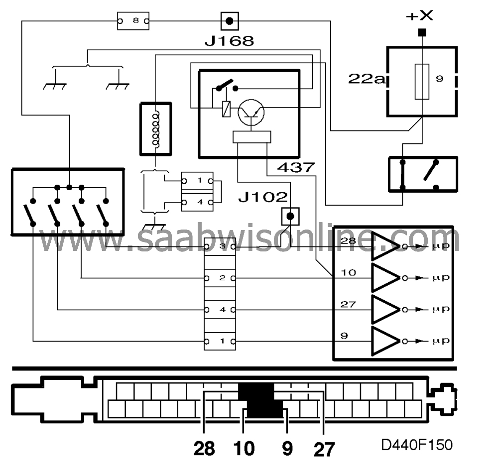
2 Check the adjustment of the gear selector position sensor
 Check the setting of the gear selector position sensor, see
 .
.
Is the gear selector position sensor correctly adjusted?
Check connector H10-1 for pin slide-out and corrosion. Check the leads connected to the transmission for shorting/continuity due to damaged insulation. If no cause of the fault can be found, change the gear selector position sensor. Proceed to point 6.
Adjust the gear selector position sensor, see
and continue with step 6.
3 Check the wiring connected to the transmission control module
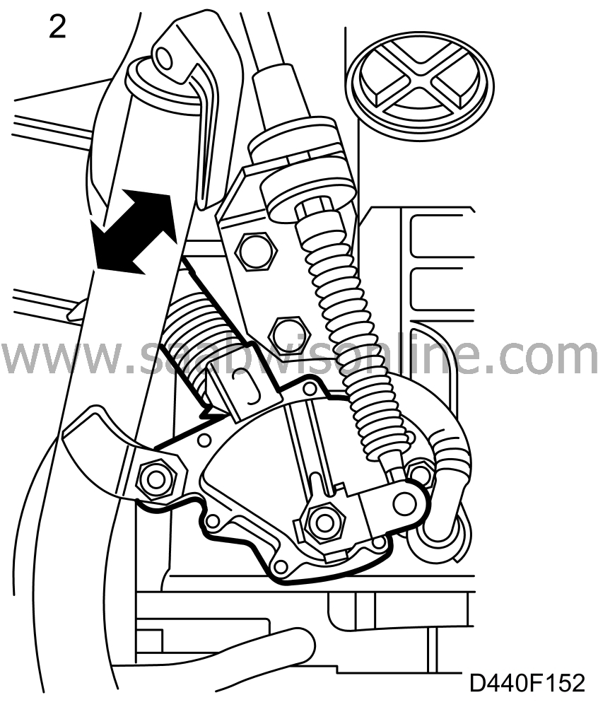
Check the wiring harness by reading the input for the gear selector position sensor with the diagnostic tool in connector H10-1 (female) with the connector pins open and connected to B+ respectively.
|
-
|
Turn the ignition to the ON position.
|
|
-
|
Select "SELECTOR POS. SENSOR"
|
|
-
|
Read "CONTACT A", "CONTACT B", "CONTACT C" and "CONTACT PA" with the selector lever in position P.
|
The diagnostic tool should show OFF when open and ON when the respective connector pin is coupled to B+.
Are the readings correct?
Continue with step 6.
Continue with point 4.
4 Check the wiring harness
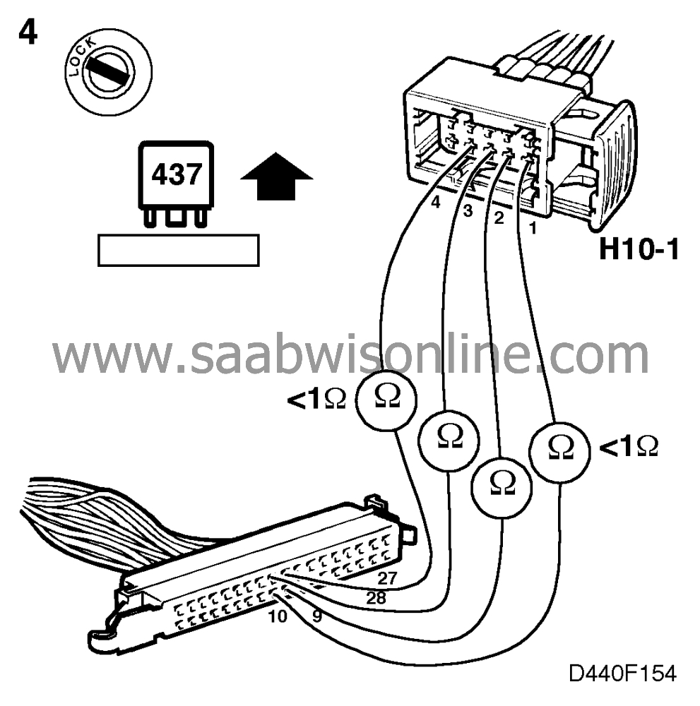
Unplug the shift-lock relay (in the main fuse box), dashboard) and check the continuity of the wiring between connector H10-1 and the transmission control module.
Is the wiring harness OK?
Plug in the shift-lock relay and continue with point 5.
Rectify the fault and proceed to point 6.
5 Check the wiring harness (contd.)
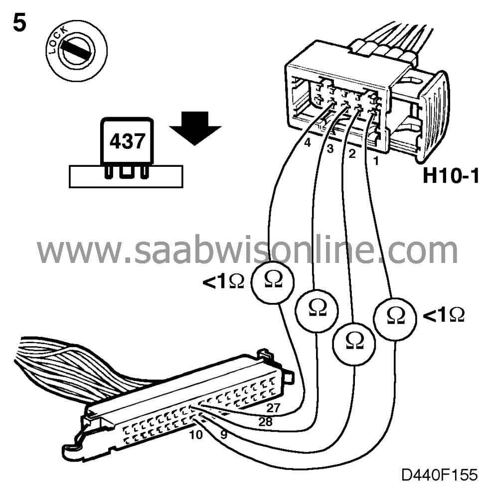
Check the continuity of the wiring harness between connector H10-1 and the transmission control module.
Is the wiring harness OK?
Continue with step 6.
Change the relay and continue with point 6.
6 Final check
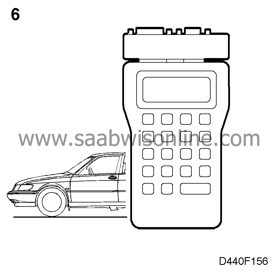
Clear the diagnostic trouble code, drive the car on test at varying engine loads and speeds for 5 minutes and check whether the diagnostic trouble code recurs.
Does the diagnostic trouble code recur?
Continue with
The remedial action taken was correct.
