Checking the shift-lock function
| Checking the shift-lock function |
| Fault symptom |
Selector lever cannot be moved from position P.
| Measures |
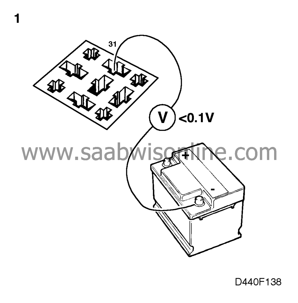
| 1. |
Remove the shift-lock relay
which is fitted in the distribution
centre under the facis in the passenger compartment.
Check the relay's ground connection and remedy any faults. Connect a voltmeter as follows |
|
| • |
relay socket, pin 31 - BATT- < 0.1
V
|
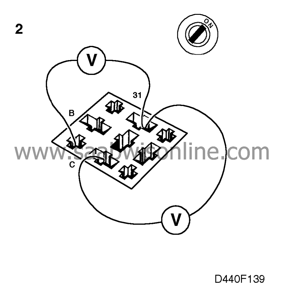
| 2. |
Check the relay's inputs from the gear position sensor and remedy
any faults. Connect a voltmeter to the relay socket as follows
with the ignition switched on:
|
|
| • |
pin B - pin 31
|
| • |
pin C - pin 31 and operate the selector lever.
Nominal voltages are in accordance with the following table.
Diagnostic trouble code P0705 is often recorded when there is a fault in connections B and C. CHECK GEARBOX is lit and the system's emergency program is activated. |
| 3. |
Check the relay's input from the brake light switch and remedy
any faults. Connect a voltmeter to the relay socket as follows with the ignition switched on:

|
|
| • |
pin R - pin 31
and depress the brake pedal. A non-depressed brake pedal should result in battery positive voltage. A depressed brake pedal should result in < 0.5 V. If the measurement result is wrong, check - fuse 9 and power supply to the fuse. - brake light switch. It might have to be adjusted or a new one fitted. - the wiring. Note that if fuse 9 is removed the starting motor interlock function is prevented from operating, which means that the selector lever can be operated. |
| 4. |
Check the functioning of the lifting magnet.
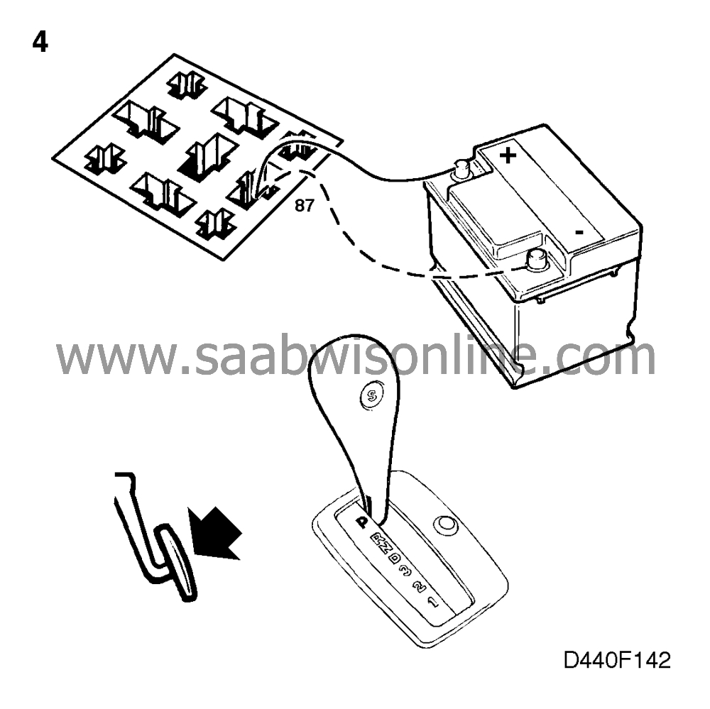
Connect alternately BATT+ and BATT- or ground to the relay socket, pin 87. BATT+ should result in activation of the lifting magnet and BATT- or ground in the lifting magnet falling. If the measuring works and points 1-3 have been carried out, fit a new shift-lock relay. If the measuring does not work, go to point 5. |
|
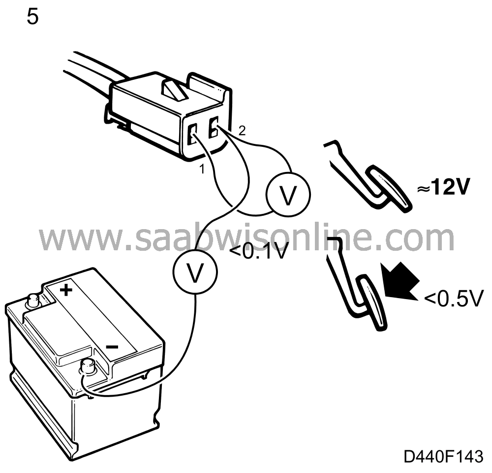
| 5. |
Check the lifting magnet and its wiring and remedy any faults.
The lifting magnet is located in the selector lever housing.
Disconnect the lifting magnet's connector. Connect a voltmeter to the
female connector as follows:
|
|
| • |
pin 2 - BATT- < 0.1 V
|
| • |
pin 1 - pin 2 ∼ BATT+ with non-depressed brake pedal < 0.5 V with
depressed brake pedal.
If the measurement results are correct, fit a new lifting magnet. If the measurement results are wrong, fit a new shift-lock relay. |
| 6. |
If it still does not function after points 1-5 have been carried out, carry on with
mechanical fault-tracing of the lifting magnet.
|
|
This project is supported by memberships and donations. If you use this site, please consider Joining SCNA and/or making a donation.
Our Friends
