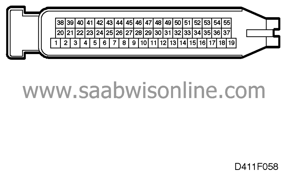
Test readings, control module connections
| Test readings, control module connections |
| Scope |
Test readings and instructions for measuring signals and levels on the Sensonic system are given in the following pages.
| Some important points to remember: |
| • |
Readings must be taken with a Breakout Box (BOB) connected between the control module and the control module connector.
|
|
| • |
Several voltage levels must be regarded as guiding values. Your common sense should tell you whether a reading is correct or not.
|
|
| • |
If any test reading is obviously wrong, use the wiring diagram to trace the leads, connectors or components which you consider should be checked more thoroughly.
|
|
| • |
Page references in the table refer to the page on which the principle of operation of the signal concerned is described, and also to the fault diagnosis schedule with a complete description of the diagnostic procedure to be followed.
|
|
| • |
All test readings are for a warm engine.
|
|
| • |
Unless otherwise stated, the ignition switch should be in the ON position.
|
|
| • |
The specified test readings are in respect of calibrated FLUKE 88/97.
|
|
> = Greater than, < = Less than, » approximately equal to, ∼ = alternating current. (LP=Logic Probe, P = select pulse; p = visible pulses)
|
pin
|
Component/Function
|
Input/Output
|
Test conditions
|
Test reading
|
Across
|
|
1
|
Not connected
|
|
|
|
|
|
2
|
Not connected
|
|
|
|
|
|
3
|
CHECK ACS warning lamp
|
Output
|
Ignition ON
Activate with the Scan tool diagnostics instrument ACS LAMP ON ACS LAMP OFF or When ignition ON synchronous with lamp on |
B+ 0 V B+ for 3 s |
18 - 3
|
|
4
|
Not connected
|
|
|
|
|
|
5
|
+50 to starting relay
|
Output
|
Starter motor cranking
Otherwise |
B+
0 V |
5 - 19
|
|
6
|
Signal from control module to clutch actuator unit which activates the actuator motor driver stage
|
Output
|
Ignition ON
Activate with the Scan tool diagnostics instrument Clutch actuator unit ON Clutch actuator unit OFF |
6 V 0 V |
6 - 17
|
|
7
|
Not connected
|
|
|
|
|
|
8
|
Brake pedal switch
|
Input
|
Ignition ON
1st gear Brake pedal depressed or Activate with the Scan tool diagnostics instrument Cruise Control ON Cruise Control OFF |
B+ 0 V B+ 0 V |
8 - 19
|
|
9
|
Cruise Control, disengagement
|
Output
|
Ignition ON
1st gear Neutral or Activate with the Scan tool diagnostics instrument Cruise Control ON Cruise Control OFF |
B+ 0 V B+ 0 V |
9 - 19
|
|
10
|
Gear selector position sensor, Power supply
|
Output
|
Ignition ON
|
5.0 V
|
10 - 35
|
|
11
|
Not connected
|
|
|
|
|
|
12
|
Throttle position, position signal from Trionic
|
Input
|
Engine ON
Idling 2500 rpm |
»
1 V
100 Hz 9%% (+) 0.9 ms (+) LP HI LO » 2 V 100 Hz 15%% (+) 1.5 ms (+) LP HI LO |
12 - 19
|
|
13
|
Engine rpm, signal from Trionic
|
Input
|
Engine ON
Idling 2500 rpm |
0.4 V 30 Hz 1.5 ms (+) LP HIp LO 1.2 V 85 Hz 1.5 ms (+) LP HI LO |
13 - 19
|
|
14
|
Gear selector movement sensor, power supply
|
Output
|
Ignition ON
|
B+
|
14 - 36
|
|
15
|
Engine load, signal from Trionic
|
Input
|
Engine ON
Front assembly RAISED Idling 2500 rpm |
30 Hz LP P LO 85 Hz LP P LO |
15 - 19
|
|
16
|
Ground, NTC sensor for clutch housing temperature
|
Input
|
Ignition ON
|
<0.1 V
|
16 - 19
|
|
17
|
Ground, reference to clutch actuator unit
|
Output
|
Ignition ON
|
<0.1 V
|
17 - 19
|
|
18
|
Battery voltage +15
|
Input
|
Ignition ON
|
<0.5 V
|
B+ - 18
|
|
19
|
Power ground
|
Input
|
Ignition ON
|
<0.1 V
|
19 - B-
|
|
20
|
Not connected
|
|
|
|
|
|
21
|
Cruise Control ON/OFF
|
Input
|
Ignition ON
Put Cruise Control in diagnostics mode Press SET/RES |
0 V |
21 - 19
|
|
22
|
Serial communication between Control Module and Clutch Actuator Unit
|
Input/Output
|
Ignition ON
|
»
1.9 V
LP HI LO |
22 - 19
|
|
23
|
Serial communication between Control Module and Clutch Actuator Unit
|
Input/Output
|
Ignition ON
|
»
3.1 V
LP HI LO |
23 - 19
|
|
24
|
Serial communication from control module to SID
|
Output
|
Ignition ON
Activate SID with the Scan tool diagnostics instrument -no fault -overheated clutch |
9-10 V LP HIp LOp 5-6 V LP HIp LOp |
24 - 19
|
|
25
|
Brake light switch
|
Input
|
Ignition ON
Brake activated Brake not activated |
B+ 0 V |
25 - 19
|
|
26
|
+50 in
|
Input
|
Starter motor cranking other positions
|
B+
0 V |
26 - 19
|
|
27
|
Gear selector position sensor Sensor voltage on lengthwise movement
|
Input
|
Ignition ON
-1- -2- -3- -4- -5- -R- |
0.3-2.0 V 3.5-4.7 V 0.3-2.0 V 3.5-4.7 V 0.3-2.0 V 3.5-4.7 V |
27 - 35
|
|
28
|
Gear selector position sensor Sensor voltage on crosswise movement
|
Input
|
Ignition ON
-1- -2- -3- -4- -5- -R- |
3.6-4.7 V 3.6-4.7 V 2.4-3.6 V 2.4-3.6 V 0.3-2.4 V 0.3-2.4 V |
28 - 35
|
|
29
|
Gear selector movement sensor, Sensor voltage
|
Input
|
Ignition ON
|
2.2 V-2.8 V
|
29 - 36
|
|
30
|
NTC sensor for clutch housing temperature
|
Input
|
Ignition ON
20C 50C 80C 100C |
3.4 V 2.1 V 1.2 V 0.7 V |
30 - 16
|
|
31
|
Wheel speed Signal from ABS LH rear wheel
|
Input
|
Ignition ON
Raise the car Rotate LH rear wheel 1/2 rev/sec |
»
5 V
15 Hz LP HIp LOp |
31 - 19
|
|
32
|
Signal from control module which activates the clutch actuator unit
|
Output
|
Ignition ON
|
3-5 V
|
32 - 17
|
|
33
|
Not connected
|
|
|
|
|
|
34
|
Ground Inductive sensor for gearbox input rpm
|
Input
|
Ignition ON
|
<0.1 V
|
34 - 19
|
|
35
|
Ground Gear selector position sensor
|
Input
|
Ignition ON
|
<0.1 V
|
35 - 19
|
|
36
|
Ground Gear selector movement sensor
|
Input
|
Ignition ON
|
<0.1 V
|
36 - 19
|
|
37
|
Battery voltage +30
|
Input
|
|
<0.5 V
|
B+ - 37
|
|
38
|
Diagnostics lead K
|
Input/Output
|
Scan tool diagnostics instrument connected diagnostics instrument not connected
|
B+ 0 V
|
38 - 19
|
|
39
|
Not connected
|
|
|
|
|
|
40
|
Not connected
|
|
|
|
|
|
41
|
Not connected
|
|
|
|
|
|
42
|
Not connected
|
|
|
|
|
|
43
|
Not connected
|
|
|
|
|
|
44
|
Not connected
|
|
|
|
|
|
45
|
Not connected
|
|
|
|
|
|
46
|
Not connected
|
|
|
|
|
|
47
|
Not connected
|
|
|
|
|
|
48
|
Inductive sensor for gearbox input rpm
|
Input
|
Raise the car
Engage 1st gear Rotate one of the front wheels 1/2 rev/sec |
0.5 V AC 50 Hz |
48 - 34
|
|
49
|
Not connected
|
|
|
|
|
|
50
|
Not connected
|
|
|
|
|
|
51
|
Not connected
|
|
|
|
|
|
52
|
Not connected
|
|
|
|
|
|
53
|
Not connected
|
|
|
|
|
|
54
|
Not connected
|
|
|
|
|
|
55
|
Not connected
|
|
|
|
|
This project is supported by memberships and donations. If you use this site, please consider Joining SCNA and/or making a donation.
Our Friends
