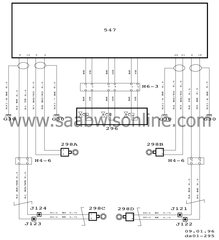
Wiring diagram, ABS2E (II)
| Wiring diagram, ABS 2E (II) |
| Component list |
|
22A
|
Fuse board in main fuse box,
dashboard
|
|
29
|
Brake light switch, on brake pedal
|
|
47Q
|
ABS (ANTI LOCK) warning lamp, in main instrument
display panel
|
|
110
|
Tachometer, in main instrument display
panel
|
|
297
|
Motor, hydraulic pump, on hydraulic brake
unit
|
|
342A
|
Fuse board in main fuse box, engine
bay
|
|
507
|
Control module, TCS, under RH front
seat
|
|
445
|
Data link connector, under dashboard by steering
wheel
|
|
508
|
Control module, Cruise Control, at far right in engine
bay below the windscreen.
|
|
540
|
Main instrument display panel, in
dashboard
|
|
547
|
ABS control module integrated in hydraulic brake
unit between the battery and the front main fuse box.
|
|
505
|
MOTRONIC control module M2.10.2, on right-hand
side behind the side trim below the A pillar
|
|
509
|
Saab Sensonic control module, on the bulkhead
partition behind the glove box
|
|
510
|
MOTRONIC control module M2.8.1, on right-hand
side behind the side trim below the A-pillar
|
|
430
|
TRIONIC control module, on right-hand side behind
the side trim below the A-pillar
|
|
H33-2
|
Black 33-pin connector, on the bracket below the
left-hand A-pillar
|
|
H33-4
|
33-pin connector, on the bulkhead partition behind
the glove box
|
|
G30
|
Grounding point, left-hand structural member behind
the battery
|
|
G33S
|
Signal ground connector bracket, below the left-
hand A pillar on the connector bracket
|
|
G33P
|
Power ground connector bracket, below the left-
hand A pillar on the connector bracket
|
|
J4
|
Crimped connection, about 50 mm from the
rheostat, towards the main instrument display panel (instrument wiring
harness)
|
|
J5
|
Crimped connection, about 190 mm from the main
fuse box in the engine bay, towards the battery (front wiring harness)
|
|
J32
|
Crimped connection, about 150 mm from the clutch
pedal and about 200 mm from the brake light switch (instrument wiring
harness)
|
|
J33
|
Crimped connection, about 200 mm from connector
H33-3 (instrument wiring harness)
|
|
J49
|
Crimped connection, about 300 mm from the
rheostat, towards the centre console (instrument wiring harness)
|
|
J56
|
Crimped connection, about 350 mm from the
rheostat, towards the centre console
|
|
J96
|
Crimped connection, about 420 mm from grounding
point G33P/S, towards the pedal assembly (instrument wiring harness)
|
|
J98
|
Crimped connection, about 130 mm from connector
H33-2 (instrument wiring harness)
|
|
J99
|
Crimped connection, about 250 mm from grounding
point G33P/S, towards the fuse holder (instrument wiring harness)
|
|
J103
|
Crimped connection, about 170 mm from the left-
hand loudspeaker connection (instrument wiring harness)
|
|
296
|
ABS valve block, on hydraulic brake
unit
|
|
298A
|
Wheel sensor, front left, on steering swivel
member
|
|
298B
|
Wheel sensor, front right, on steering swivel
member
|
|
298C
|
Wheel sensor, rear left, on LH rear wheel
hub
|
|
298D
|
Wheel sensor, rear right, on RH rear wheel
hub
|
|
547
|
ABS control module integrated in hydraulic brake
unit between the battery and the front main fuse box.
|
|
H4-6
|
4-pin connector on bracket below the left-hand A
pillar
|
|
H6-3
|
6-pin connector on the hydraulic brake
unit
|
|
J121
|
Crimped connection, about 500 mm from the point
where the rear wiring harness branches off, towards the fuel pump
|
|
J122
|
Crimped connection, about 450 mm from the point
where the rear wiring harness branches off, towards the fuel pump
|
|
J123
|
Crimped connection, about 400 mm from the point
where the rear wiring harness branches off, towards the fuel pump
|
|
J124
|
Crimped connection, about 350 mm from the point
where the rear wiring harness branches off, towards the fuel pump
|
|
G30
|
Grounding point, left-hand structural member behind the
battery
|


