Measuring procedure and data
| Measuring procedure and data |
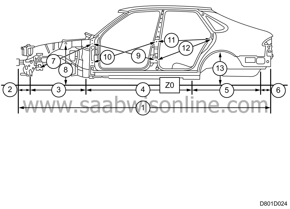
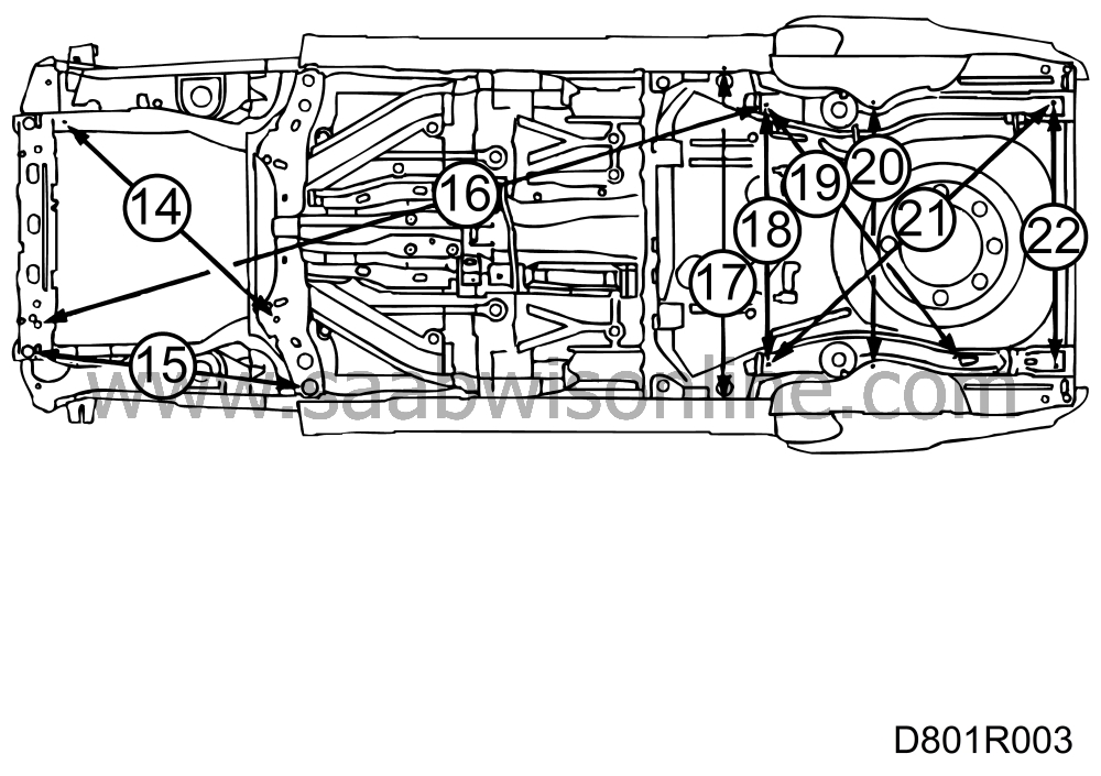
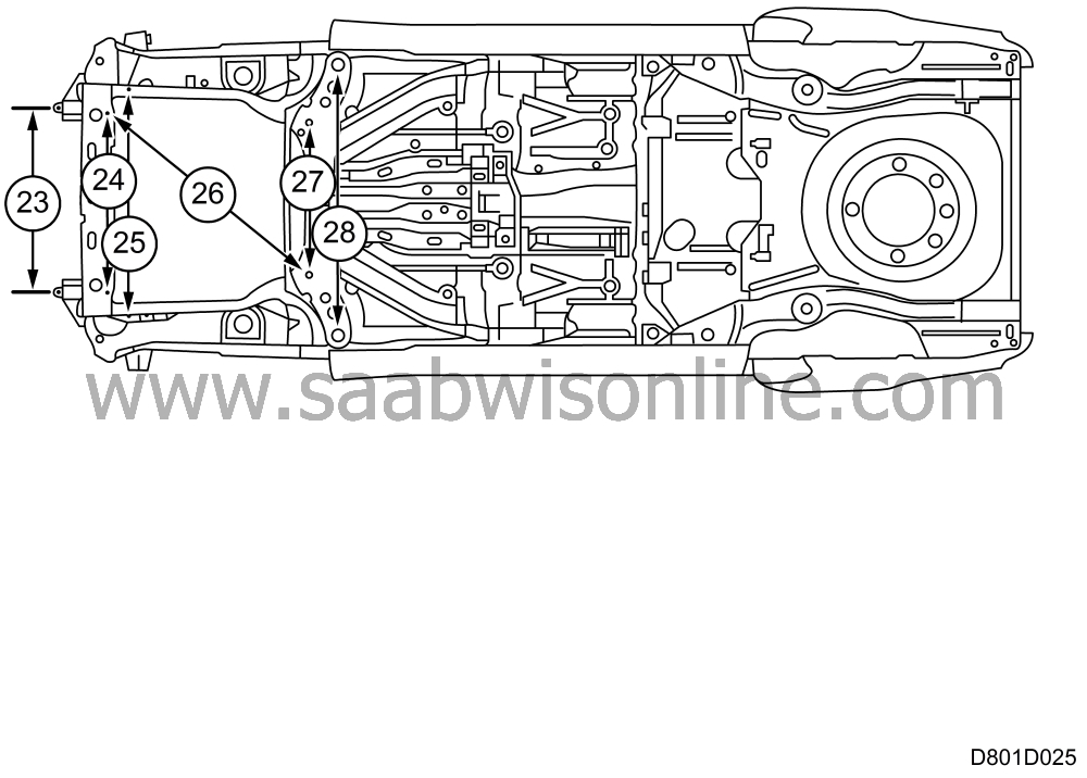
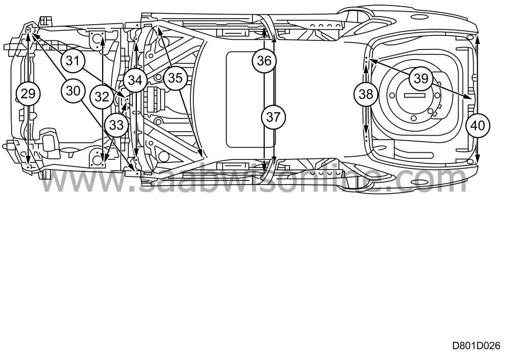
These measurements are suitable to use to decide if the car should be mounted on an alignment jig.
The directions of the measurements are given in the "Direction" column in the table below, as follows:
X = measure lengthwise, along the body
Y = measure sideways, across the body
Z = measure heightwise, up along the side of the body
The digit in the column "Measure" indicates the tolerance for:
1 = engineering measurements according to coordinates
2 = actual measurements, generally direct diagonal measurements
3 = tolerance for best fit
Each coordinate originates from a datum. Since datum line X0 cannot be used in practice, it is not shown.
Datum line Y0. This is the centre line of the body, dividing it into left and right halves. Transverse measurements are specified between two measuring points. To measure the dimension on one side only, mark out the Y0 line between the holes as shown on the drawing and then halve the dimension and tolerance.
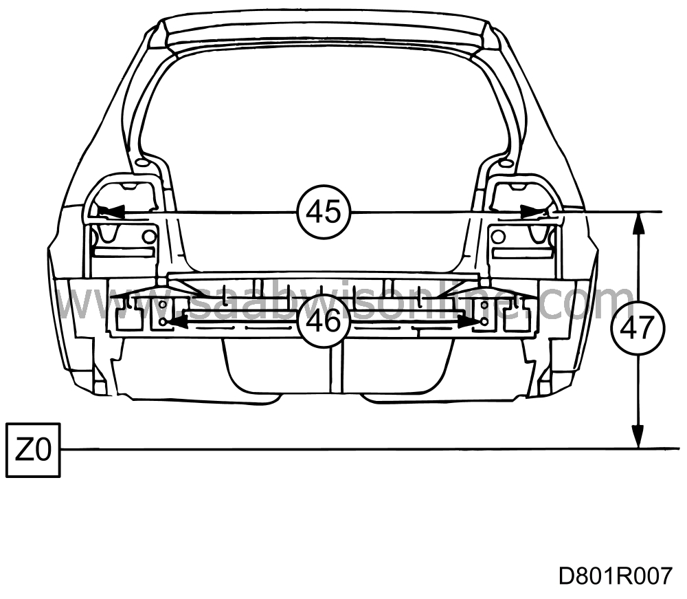
Datum line Z0. The line is situated below the body. See pos. 8, 13 and 47.
Other symbols
* = hole centre is the origin for measurements.
| Measuring procedure and data 5-D |
|
Item No.
|
|
Dimension, mm
|
Measuring points
|
Direction
|
|
1
|
|
4198.0 ± 6
|
Total length. Front bumper member(*) - bumper bracket on rear edge of rear bumper abutment
|
X1
|
|
2
|
|
198.0 ± 1
|
Front subframe bracket(*) - bumper bracket(*)
|
X1
|
|
3
|
|
885.5 ± 1
|
Front subframe bracket(*) - rear subframe bracket, mounting(*)
|
X1
|
|
4
|
|
1737.5 ± 1
|
Rear subframe bracket, mounting(*) - front guide hole frame member(*)
|
X1
|
|
5
|
|
1238.0 ± 1
|
Front guide hole frame member(*) - rear hole, frame member(*)
|
X1
|
|
6
|
|
117.3 ± 1
|
Rear hole, frame member(*) - bumper bracket on rear edge of rear bumper abutment
|
X1
|
|
7
|
|
984.6 ± 1
|
Punched hole in bumper bracket(*) - bolt hole in upper hinge(*)
|
X2
|
|
8
|
|
790.7 ± 1
|
Z0 - damper bracket in front wheel housing, inner hole(*)
|
Z1
|
|
9
|
|
1101.0 ± 1
|
Bolt hole in upper hinge, front edge door opening(*) - lower hinge, B-pillar(*)
|
Diag. 3
|
|
10
|
|
1136.0 ± 1
|
Lower hinge, front edge(*) - upper hinge, B-pillar(*)
|
Diag. 3
|
|
11
|
|
842.0 ± 1
|
Upper hinge, B-pillar(*) - lower bolt hole for lock pin(*)
|
Diag. 3
|
|
12
|
|
877.0 ± 1
|
Lower hinge, B-pillar(*) - lower bolt hole for lock pin(*)
|
Diag. 3
|
|
13
|
|
644.6 ± 1
|
Z0 - damper mounting in rear wheel housing (*)
|
Z1
|
|
Item No.
|
|
Dimension, mm
|
Measuring points
|
Direction
|
|
14
|
|
1136.0 ± 1
|
Rear subframe bracket(*) - Front hole, front engine mounting(*)
|
Diag. 1
|
|
15
|
|
1095,7 ± 1
|
Outer hole in cross member(*) - Guide hole in front cross member(*)
|
X1
|
|
16
|
|
2902.7 ± 1
|
Front subframe bracket(*) - Hole on inside of rear axle mounting(*)
|
Diag. 2
|
|
17
|
|
1276.0 ± 1
|
Distance between sill flanges
|
Y1
|
|
18
|
|
942.6 ± 1
|
Distance between holes on inside of rear axle mountings(*) RH-LH side
|
Y1
|
|
19
|
|
1403.4 ± 1
|
Front of oval hole in frame member - hole on inside of rear axle mounting(*)
|
Diag. 2
|
|
20
|
|
1058.0 ± 1
|
Distance between damper mountings(*) RH-LH side
|
Y1
|
|
21
|
|
1445.9 ± 1
|
Rear hole in frame member(*) - hole on inside of rear axle mounting(*)
|
Diag. 2
|
|
22
|
|
1010.0 ± 1
|
Distance between rear hole in frame member(*) RH-LH side
|
Y1
|
|
Item No.
|
|
Dimension, mm
|
Measuring points
|
Direction
|
|
23
|
|
914.0 ± 1
|
Distance between hole in damper mountings(*) RH-LH side
|
Y1
|
|
24
|
|
614.0 ± 1
|
Distance between hole in front subframe brackets(*) RH-LH side
|
Y1
|
|
25
|
|
919.0 ± 1
|
Distance between front hole in front engine mountings(*) RH-LH side
|
Y1
|
|
26
|
|
1100.8 ± 1
|
Front subframe bracket(*) - rear subframe bracket(*)
|
Diag. 1
|
|
27
|
|
754.0 ± 1
|
Distance between rear subframe brackets(*) RH-LH side
|
Y1
|
|
28
|
|
1200.0 ± 1
|
Distance between outer holes in cross member(*) RH-LH side
|
Y1
|
|
Item No.
|
|
Dimension, mm
|
Measuring points
|
Direction
|
|
29
|
|
1250.0 ± 1
|
Distance between front bolt hole in wing flanges(*) RH-LH side
|
Y2
|
|
30
|
|
1610,6 ± 1
|
Front bolt hole in wing flange(*) - rear hole in bonnet hinge(*)
|
Diag. 2
|
|
31
|
|
1101.2 ± 1
|
Distance between bolt hole in middle wiper spindle mounting(*) - front bolt hole in wing flange(*)
|
Diag. 2
|
|
32
|
|
1152.2 ± 1
|
Distance between rear holes in MacPherson strut mountings(*) on LH and RH sides
|
Y1
|
|
33
|
|
624.9 ± 1
|
Distance between bolt hole in middle wiper spindle mounting(*) - rear bolt hole in damper mounting(*)
|
Diag. 2
|
|
34
|
|
1086.4 ± 1
|
Distance between bolt holes in wiper spindle mountings on LH and RH sides(*)
|
Y1
|
|
35
|
|
1371.0 ± 2
|
Maximum distance between diagonally opposite top and bottom corners of windscreen aperture
|
Diag. 3
|
|
36
|
|
1332.0 ± 1
|
Distance between upper bolt holes, lower seatbelt mounting, B-pillars R-L side (*)
|
Y1
|
|
37
|
|
1131.0 ± 1
|
Distance between upper bolt holes, upper seatbelt mounting, in B-pillars R-L side(*)
|
Y1
|
|
38
|
|
652.0 ± 1
|
Distance between tailgate outer hinge holes(*)
|
Y1
|
|
39
|
|
1292.8 ± 1
|
Y0 guide holes(*) - outer hole hinge mounting(*)
|
Diag. 2
|
|
40
|
|
1195.0 ± 2
|
Distance between side panel corners in luggage compartment opening
|
Y3
|
|
Item No.
|
|
Dimension, mm
|
Measuring points
|
Direction
|
|
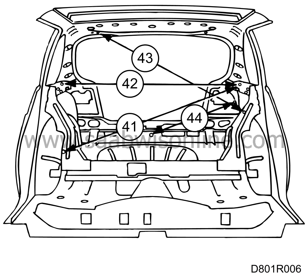
41
|
|
1294.5 ± 1
|
Bolt hole in reinforcement by rear wheel housing(*) - bolt hole in reinforcement on inside side panel(*)
|
Diag. 2
|
|
42
|
|
1263.0 ± 1
|
Distance between bolt holes in reinforcement member on inner side panel on LH and RH sides(*)
|
Y1
|
|
43
|
|
1515.5 ± 1
|
Outer hole hinge mounting(*) - guide hole in side panel by rear light frame(*)
|
Diag. 2
|
|
44
|
|
737.2 ± 1
|
Y0 guide hole - lower outer bolt hole in rear light frame(*)
|
Diag. 2
|
|
Item No.
|
|
Dimension, mm
|
Measuring points
|
Direction
|
|
45
|
|
1364.0 ± 1
|
Distance between lower outer bolt hole in rear light frame(*)
|
Y1
|
|
46
|
|
1000.0 ± 1
|
Distance between bumper brackets in rear bumper abutment(*)
|
Y1
|
|
47
|
|
750.5 ± 1
|
Z0 - lower outer bolt hole in rear light frame(*)
|
Z1
|
|
Item No.
|
|
Dimension, mm
|
Measuring points
|
Direction
|
|
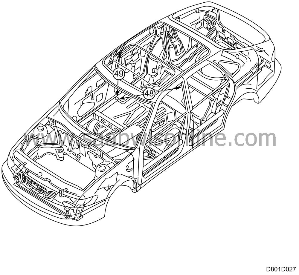
48
|
|
1517.0 ± 1
|
Upper bolt hole, lower seatbelt mounting in B-pillar lower end(*) - upper bolt hole, upper seatbelt mounting in B-pillar(*)
|
Diag. 2
|
|
49
|
|
894.0 ± 1
|
Upper bolt hole, lower seatbelt mounting in B-pillar lower end(*) - upper bolt hole, upper seatbelt mounting in B-pillar(*)
|
Z1
|
| Body dimensions 3-D |
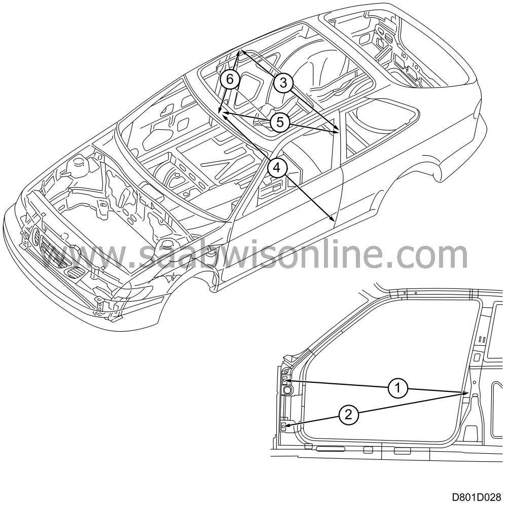
Specific dimensions that apply to the 3-door body.
|
Item No.
|
|
Dimension, mm
|
Measuring points
|
Direction
|
|
1
|
|
1232.0 ± 1
|
Bolt hole in upper hinge front edge door opening(*) - upper bolt hole striker plate mounting(*)
|
Diag. 3
|
|
2
|
|
1265.0 ± 1
|
Lower hinge front edge(*) - upper bolt hole in striker plate mounting(*)
|
Diag. 3
|
|
3
|
|
1127.0 ± 1
|
Distance between upper bolt holes, upper seatbelt mounting, in B-pillars R-L side(*)
|
Y1
|
|
4
|
|
1350.0 ± 1
|
Distance between upper bolt holes, lower seatbelt mounting in B-pillars R-L side(*)
|
Y1
|
|
5
|
|
1516.0 ± 1
|
Upper bolt hole, lower seatbelt mounting in B-pillar lower end(*) - upper bolt hole, upper seatbelt mounting in B-pillar(*)
|
Diag. 2
|
|
6
|
|
881.0 ± 1
|
Upper bolt hole, lower seatbelt mounting in B-pillar lower end - upper bolt hole, upper seatbelt mounting in B-pillar(*)
|
Z1
|
| Measuring procedure and data, convertible |
The unique dimensions for the Saab 900 Convertible are given below. For other dimensions, refer to the 3 and 5-door dimensions.
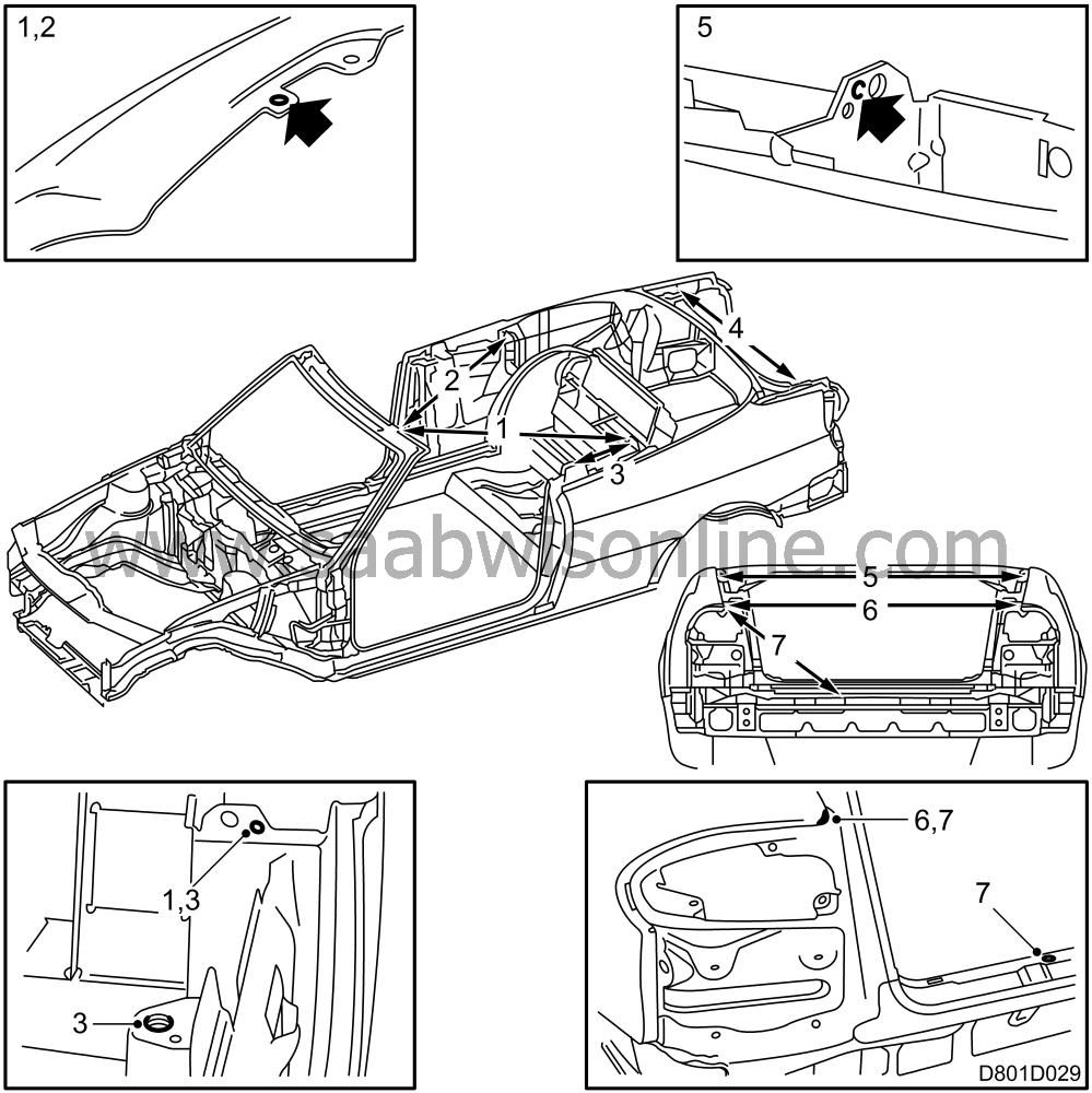
| Item No. | Dimension, mm | Measuring points | |
|
1
|
1249.0 ± 2
|
Left mounting hole for lock fitting in windscreen member (*) - guide hole by soft top mechanism mounting left side (*)
|
|
|
2
|
1622.0 ± 3
|
Left mounting hole for lock fitting in windscreen member (*) - guide hole by soft top mechanism mounting right side (*)
|
|
|
3
|
430.0 ± 2
|
Bolt hole belt guide front seat belt (*) -
rear edge
of soft top mechanism mounting plate, at top edge R-L side.
|
|
|
4
|
1169.0 ± 2
|
Middle hole mounting for tailgate hinges, R-L side. Measure on level surface above holes.
|
|
|
5
|
1227.0 ± 2
|
Rear upper corner side panels, R-L side
|
|
|
6
|
1100.0 ± 2
|
Rear upper corner by rear light, R-L side
|
|
|
7
|
521.0 ± 2
|
Rear corner side panel by rear light - square hole by boot lid lock bracket (*)
|
|
|
8
|
1236.0 ± 2
|
Bolt hole belt guide front seatbelt R-L side (*)
|
|


