B1343
| B1343 |
Solar sensor, open circuit
Conditions
Control module input pin 34, open circuit or shorted to Batt+Diagnostic procedure
If diagnostic trouble code B1515 has been generated it should be dealt with first. See .
.
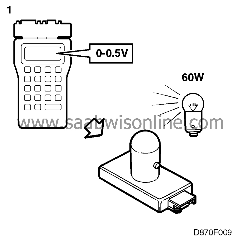
| 1. |
Connect the ISAT and obtain a "SOLAR SENSOR VALUE" readout. This value should vary between 0 and 0.155 V, depending on light intensity. Illuminate the solar sensor with a lamp (incandescent bulb) and check that the voltage increases. Since the solar sensor mainly measures infrared radiation (heat), a fluorescent lamp cannot be used for this test.
|
|
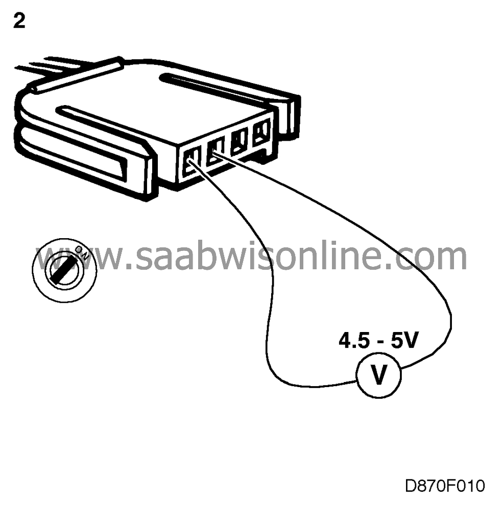
| 2. |
Unplug the solar sensor's connector and measure the voltage at the connector. It should be about 4.5 5 V. If not, proceed to point 4.
|
|
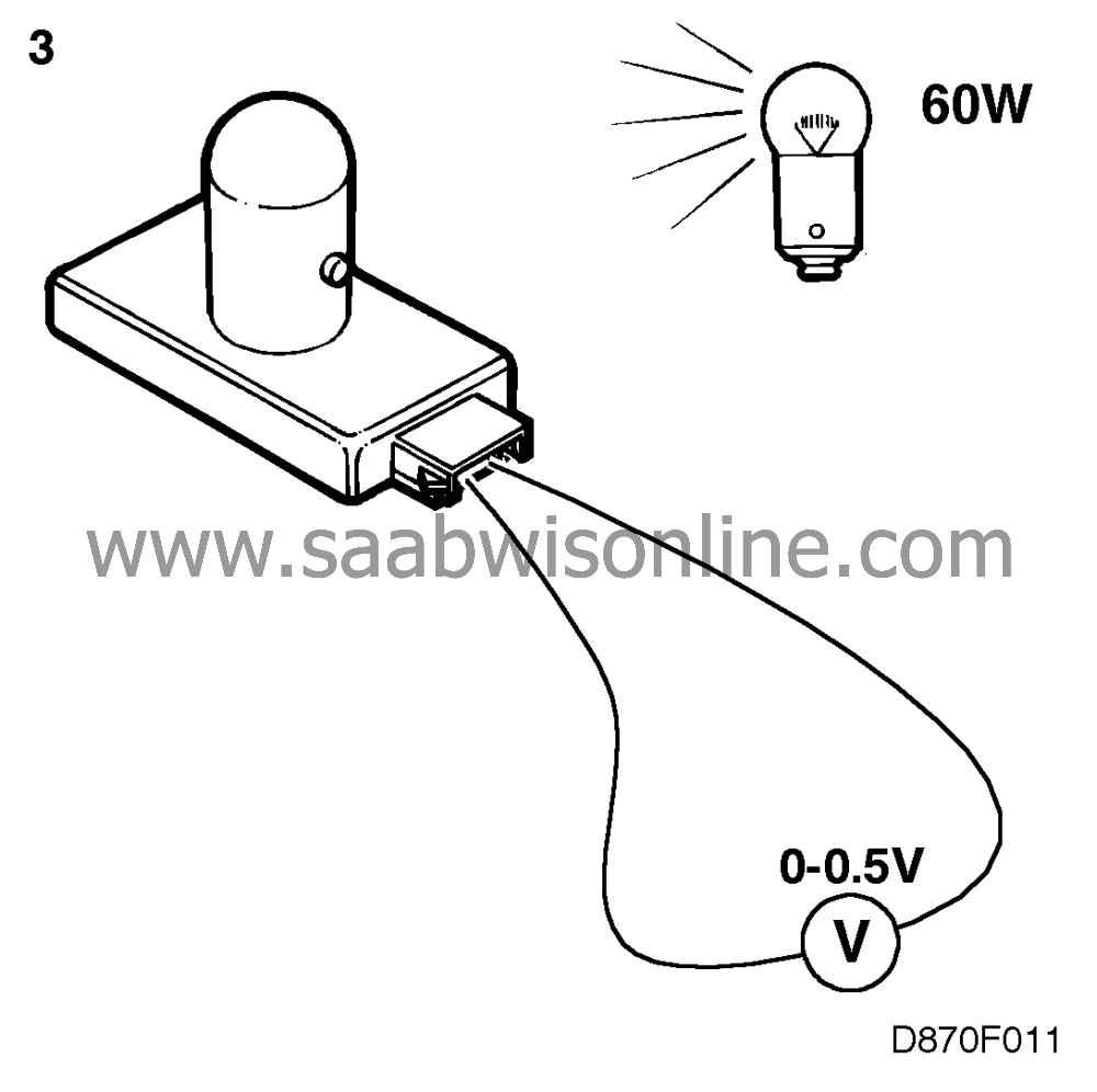
| 3. |
Illuminate the solar sensor with a lamp and at the same time measure the voltage across the sensor's connections. It should be 0 - 0.5 V. If no voltage reading can be obtained, fit a new solar sensor. Clear the diagnostic trouble code and check whether it is generated afresh.
|
|
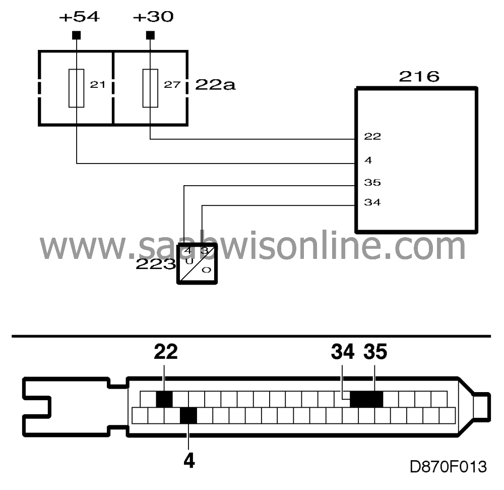
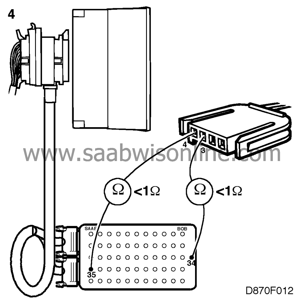
| 4. |
Unplug the ACC control module's connector. Plug a BOB into the connector and check the wiring for continuity as follows:
|
|
| • |
take a reading across pin 4 of the solar sensor's connector and pin 35 of the ACC control module.
|
| • |
take a reading across pin 3 of the solar sensor and pin 34 of the ACC control module.
Rectify any fault in the wiring. |
| 5. |
If the fault persists, proceed to section
|
|
This project is supported by memberships and donations. If you use this site, please consider Joining SCNA and/or making a donation.
Our Friends
