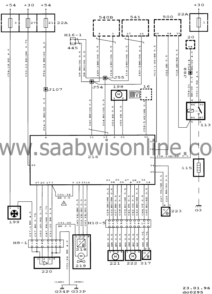
Wiring diagram, ACC
| Wiring diagram, ACC |
| Component locations |
|
22A
|
Fuse holder in the dashboard
|
|
16
|
Rheostat on dashboard to left (LHD) or right (RHD) of steering wheel
|
|
113
|
Electrically heated rear window relay, in dashboard. Plac. 22B:H (LHD) and plac. 22B:G (RHD)
|
|
198
|
Recirculation flap motor, on climate control unit behind glove box
|
|
199
|
Ventilation fan motor, on climate control unit in bulkhead space
|
|
216
|
ACC control module in centre of dashboard
|
|
217
|
Mixed-air temperature sensor, on climate control unit behind glove box
|
|
218
|
Indoor temperature sensor between switches for electric heating of front seats
|
|
220
|
Fan control unit, on climate control unit behind glove box
|
|
221
|
Air distribution motor, on climate control unit behind ACC control module
|
|
222
|
Air-blending flap motor, on climate control unit behind glove box
|
|
223
|
Solar sensor, centrally mounted on dashboard
|
|
500
|
ICE control module, adjacent to steering column above the relay holder
|
|
540
|
Main instrument display panel on dashboard
|
|
541
|
SID unit in centre of dashboard
|
|
H10-5
|
On the climate control unit
|
|
J54
|
Crimped connection, about 600 mm from the rheostat towards the main instrument display unit (instrument wiring harness)
|
|
J55
|
Crimped connection, about 550 mm from the rheostat towards the main instrument display unit (instrument wiring harness)
|
|
G34P
|
Grounding point, control module bracket (Power), below the right-hand A pillar
|


