Noise from A/C system
| SERVICE INFORMATION | |
| Bulletin Nbr: | 854-2081 |
| Date: ........... | May 1999 |
| Market: | not US, CA |
| Noise from A/C system |
| Cars affected |
Saab 900 M94 - M98
| Background |
This SI is intended to prevent unnecessary repairs while ensuring the correct cause of the fault is rectified.
Various types of noise may be heard from the A/C system. Some of these are normal and others can occur in the event of a malfunctioning expansion valve, antifrost thermostat or compressor.
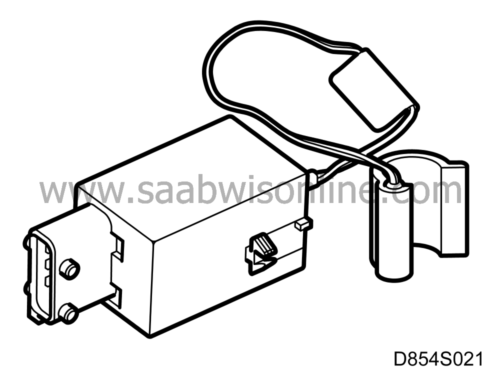
Antifrost thermostat malfunctions on cars within VIN intervals T2037750 - W2019950 (3D/5D) and T7010027 - W7008292 (CV) have caused a large number of compressor breakdowns. It is essential to make sure the antifrost thermostat on cars within the above VIN interval is fitted with a white plastic clip instead of a metal one. It is also necessary on these cars to replace the thermostatic switch on the compressor as its service life is limited by the number of times it is activated. This number will increase if there is a malfunction in the antifrost thermostat, which will cause the compressor to break down.
| Parts required |
50 45 976 Antifrost thermostat
43 83 824 Thermostatic switch Seiko-Seki up to and including VIN S2002729 (3D/5D) and S7013039 (CV)
46 32 014 Thermostatic switch Seiko-Seki from VIN S2002730 (3D/5D) and S7013040 (CV)
50 45 166 Expansion valve
| Symptoms, identifying different noises |
The following list can be used to aid the identification of different noises and their possible causes.
| 1. |
It is normal to hear a noise from the compressor’s electromagnetic clutch when it engages, provided there is correct play. See Service Information 854-1427 for Saab 9000.
|
|
| 2. |
A hissing sound coming from the evaporator like steam being released from the system is completely normal (but can be amplified if the expansion valve is malfunctioning).
|
|
| 3. |
Rattling is caused by A/C pipes touching the body, especially under the battery tray. See A.
|
|
| 4. |
A very high frequency howling sound occurring when the compressor starts or is engaged. The sound can be heard best at approx. 70 km/h in fifth gear (1800 - 2000 rpm) or when stationary after the engine has been running for a few minutes. The cause is the expansion valve. See B.
|
|
| 5. |
A repetitive humming sound that is not dependent on engine speed or vehicle speed is caused by the expansion valve. See B.
|
|
| 6. |
High frequency whistling caused by the expansion valve. See B.
|
|
| 7. |
A metallic sound heard from the compressor can be caused by internal damage. See C.
|
|
| Procedure |
For cars within VIN interval;
T2037750 - W2019950 (3D/5D) and
T7010027 - W7008292 (CV):
| - |
If the antifrost thermostat clip is metal, change to a new antifrost thermostat with plastic clip, see page 4.
|
|
| - |
Change the thermostatic switch on the compressor, see page 6.
|
|
A description of the expansion valve and compressor can be found in WIS.
| A. |
Make sure the A/C pipes are not touching the body, especially under the battery tray
|
|
| - |
Adjust the pipes so that they are free of the body.
|
| B. |
Change expansion valve, see WIS.
If the problem persists, continue with C. |
|
| C. |
Check the bearing play with the compressor clutch unladen. Remove the belt and check the runout and bearing play.
If there is play in the bearing, remove the clutch and see whether the shaft from the compressor rotor has darkened (run warm) and if refrigerant is leaking from the shaft. |
|
| - |
If there are neither signs of the shaft having darkened nor any leaks but only play in the bearing, the clutch must be changed.
|
| - |
If the shaft has darkened or if there are refrigerant leaks, the compressor must be changed. See WIS.
|
|||||||
| Warranty/Time Information |
Antifrost thermostat
Failed Object: 87062Fault/Reason code: 10
Location code: 09
Repair/Action code: 01
Time: 0.7 hours
| Warranty/Time Information |
Thermostatic switch
Failed Object: 87033Fault/Reason code: 74
Location code: 09
Repair/Action code: 01
Time:
4-cyl. 0.7 hrs.
6-cyl. 0.2 hrs.
| Warranty/Time Information |
A/C pipes
Failed Object: See respective A/C pipeFault/Reason code: 43
Location code: 09
Repair/Action code: 05
Time: 0.2 hrs.
| Warranty/Time Information |
Expansion valve
Failed Object: 87021Fault/Reason code: 45
Location code: 09
Repair/Action code: 01
Time:
4-cyl. 0.2 hrs.
6-cyl. 0.5 hrs.
Associated work
Failed Object 12803 0.3 hrs.
Failed Object 12804 1.0 hrs.
Failed Object 12872 0.2 hrs.
| Warranty/Time Information |
Compressor clutch
Failed Object: 87011Fault/Reason code: 40
Location code: 09
Repair/Action code: 01
Time:
4-cyl. 0.7 hrs.
6-cyl. 0.8 hrs.
| Warranty/Time Information |
Compressor
Failed Object: 87010Fault/Reason code: 40
Location code: 09
Repair/Action code: 01
Time:
4-cyl. I 0.4 hrs.
4-cyl T 0.7 hrs.
6-cyl. 0.6 hrs.
Associated work
Failed Object 12803 0.3 hrs.
Failed Object 12804 1.0 hrs.
Failed Object 12872 0.2 hrs.
| Antifrost thermostat |
To remove
For cars within the following VIN intervalT2037750 - W2019950 (3D/5D) and
T7010027 - W7008292 (CV).
| 1. |
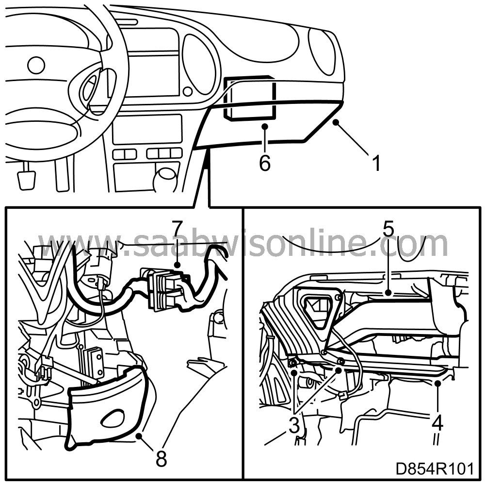
Remove the glove box.
|
|
| 2. |
Remove the centre console’s side panel.
|
|
| 3. |
Cars with passenger airbag: Remove the knee bar.
|
|
| 4. |
Remove the floor air duct.
|
|
| 5. |
Remove the air duct leading to the dashboard’s side vent.
|
|
| 6. |
Cars with automatic transmission:
|
|
| 6.a. |
Remove the transmission control module from its bracket on the bulkhead and leave it suspended from the cables.
|
| 6.b. |
Remove the bracket.
|
| 7. |
If necessary, unplug the wiring harness to the dashboard and put it to one side.
|
|
| 8. |
Fold back the carpet and remove the protective cover.
|
|
| 9. |
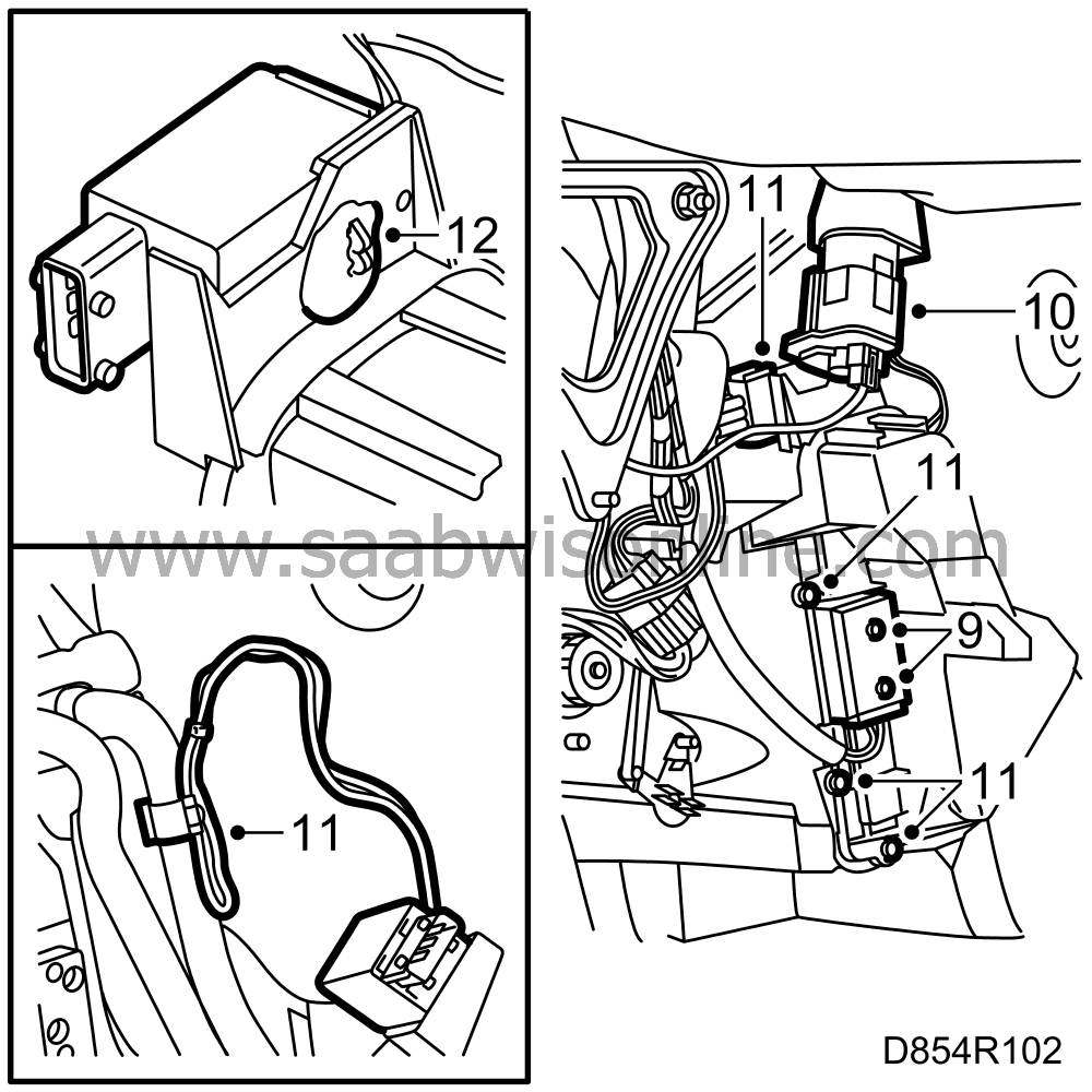
Remove the screws securing the fan control unit (cars with ACC).
|
|
| 10. |
If necessary, remove the recirculation motor.
|
|
| 11. |
Remove the end cover on the heating and ventilation unit. The clip can be broken off to make removal easier as the end cover is to be screwed on when refitted. Uncouple the antifrost thermostat electrical connection and remove the clip for the sensor on the low pressure pipe.
|
|
| 12. |
Use a screwdriver and break the adhesive securing the antifrost thermostat clip to the end cover. Remove the antifrost thermostat from the end cover.
|
|
To fit
| 1. |
Fit the new antifrost thermostat on the end cover. If necessary, apply butyl tape between the antifrost thermostat and the end cover to prevent it rattling.

|
|
| 2. |
Connect the antifrost thermostat sensor to the low pressure pipe with the plastic clip.
|
|
| 3. |
Plug in the connector and replace the end cover on the heating and ventilation unit. Put the ventilation fan on maximum speed and check that condensation is not leaking from the evaporator. Fit a new seal between the end cover and the heating and ventilation unit where necessary.
|
|
| 4. |
Refit the fan control unit and tighten the screws (cars with ACC).
|
|
| 5. |
Fit the recirculation motor.
|
|
| 6. |
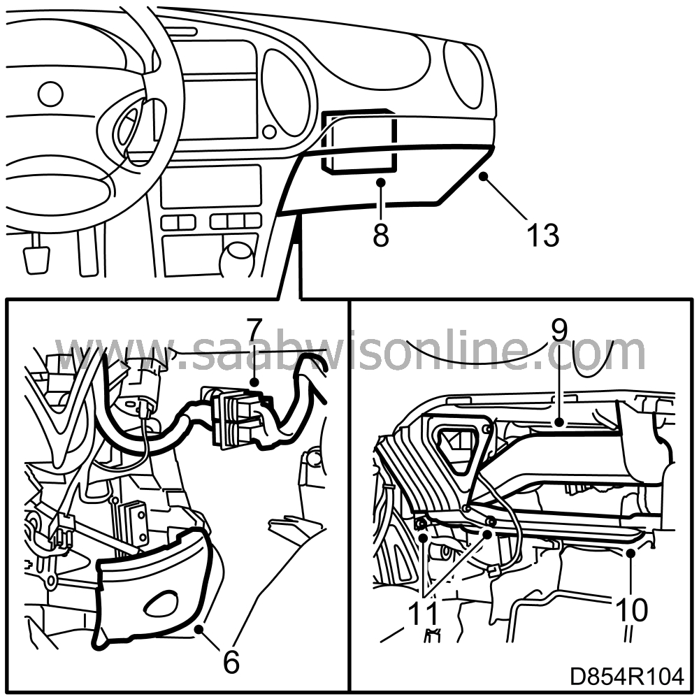
Refit the protective cover.
|
|
| 7. |
Plug in the wiring harness for the dashboard where applicable.
|
|
| 8. |
Cars with automatic transmission:
|
|
| 8.a. |
Screw the bracket for the transmission control module to the bulkhead.
|
| 8.b. |
Refit the control module.
|
| 9. |
Put the air duct for the dashboard’s side vent in place.
|
|
| 10. |
Put the floor duct in place.
|
|
| 11. |
Cars with passenger airbag: Refit the knee bar and tighten the screws.
|
|
| 12. |
Refit the centre console’s side panel.
|
|
| 13. |
Fit the glove box and tighten the screws.
|
|
| Thermostatic switch |
To remove
For cars within the following VIN interval:T2037750 - W2019950 (3D/5D) and
T7010027 - W7008292 (CV).
For cars with 6-cyl. engine go to step 3.
| Note | ||
|
It is not necessary to evacuate or discharge any refrigerant to perform this repair. |
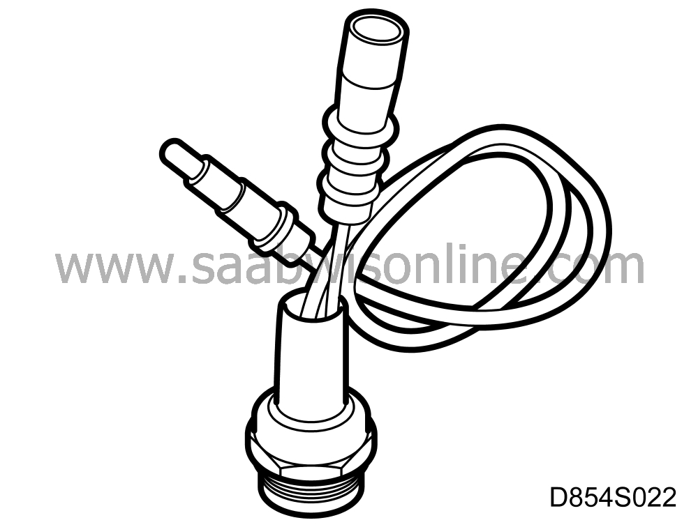
| 1. |
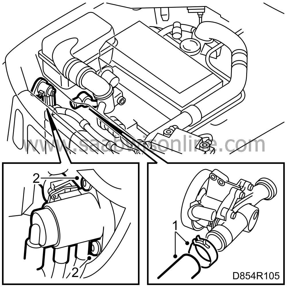
Drain the coolant and remove the lower radiator hose leading to the water pump (4-cyl.).
|
|
| 2. |
Undo the control valve if necessary (turbo).
|
|
| 3. |
Remove the cable tie and disconnect the thermostatic switch.
|
|
| 4. |
Cut off a 19 mm ring spanner to a length of approx. 120 mm.

|
|
| 5. |
Remove the thermostatic switch using the ring spanner.
|
|
To fit
| 1. |
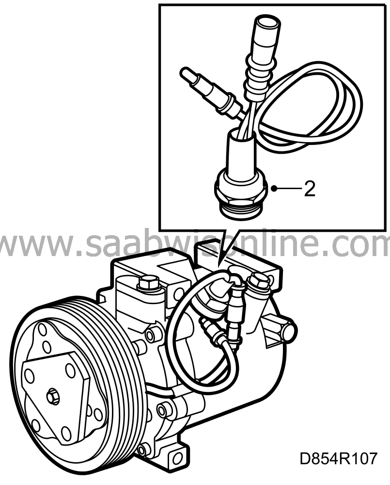
Transfer the plastic sleeve for the electrical connection to the new thermostatic switch.
|
|
| 2. |
Fit the new thermostatic switch.
|
|||||||
| 3. |
Connect the leads and secure them with a cable tie.
|
|
| 4. |
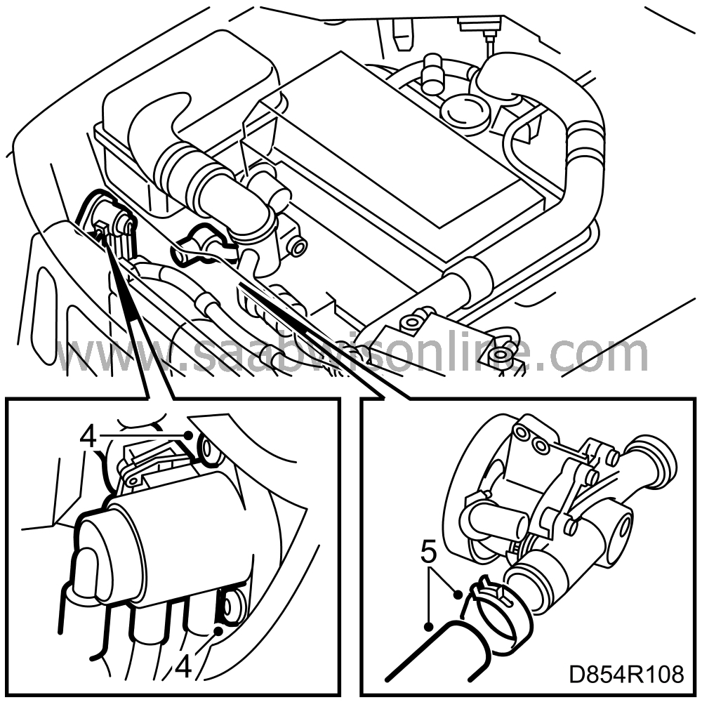
Fit the control valve (turbo).
|
|
| 5. |
Fit the lower radiator hose leading to the water pump (4-cyl.).
|
|
| 6. |
Fill with coolant (4-cyl.) and bleed the system.
|
|
| 7. |
Perform a pressure test on the cooling system.
|
|


