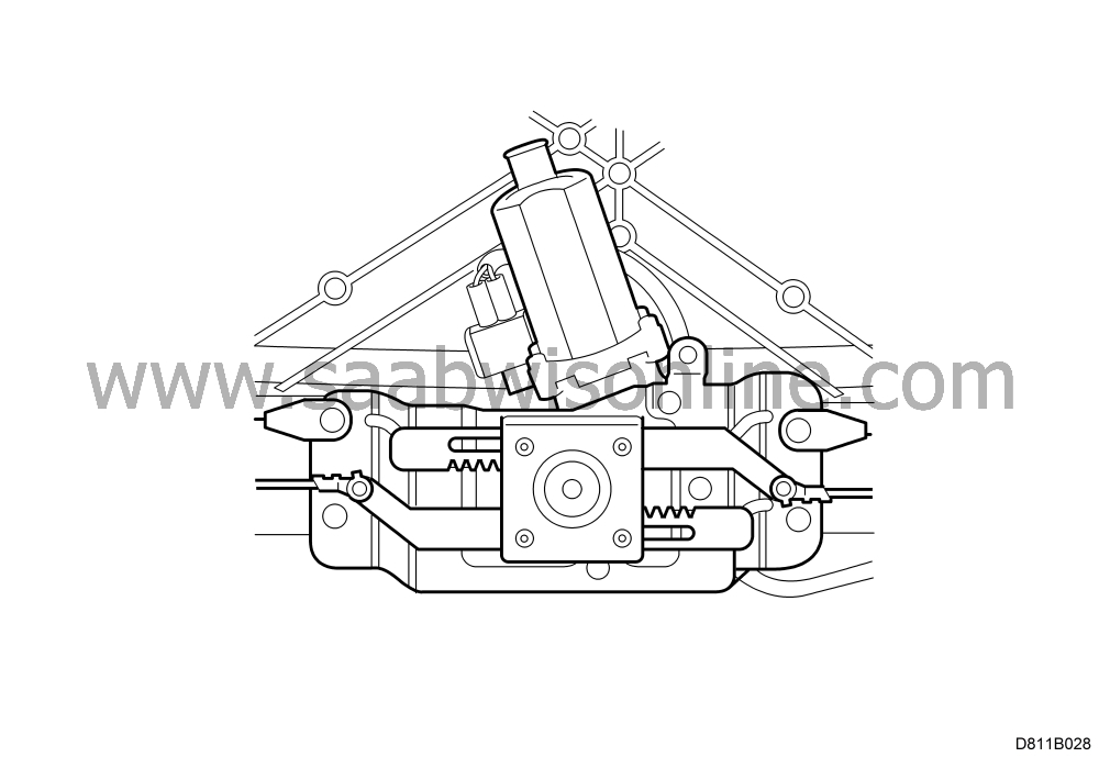
Replacement, fifth bow locking motor
|
MODIFICATION INSTRUCTION
|
|
Bulletin Nbr:
|
811-1961
|
|
Date:
...........
|
March 1998
|
|
Market:
|
ES, GR, IT, PT
|
|
|
Replacement, fifth bow locking motor
|
Cars in stock should be rectified before delivery.
Cars already delivered should be rectified next time they are brought in for regular servicing or repairs.
Saab 900 Cabriolet up to chassis number V7010305.
On certain cars, the fifth bow locking motor can seize when the top is folded up or down. This means that the top cannot be operated using the ROOF button.
To avoid this problem, the fifth bow locking motor should be replaced as described below.
74 97 878, spare part kit for replacement of locking motor.
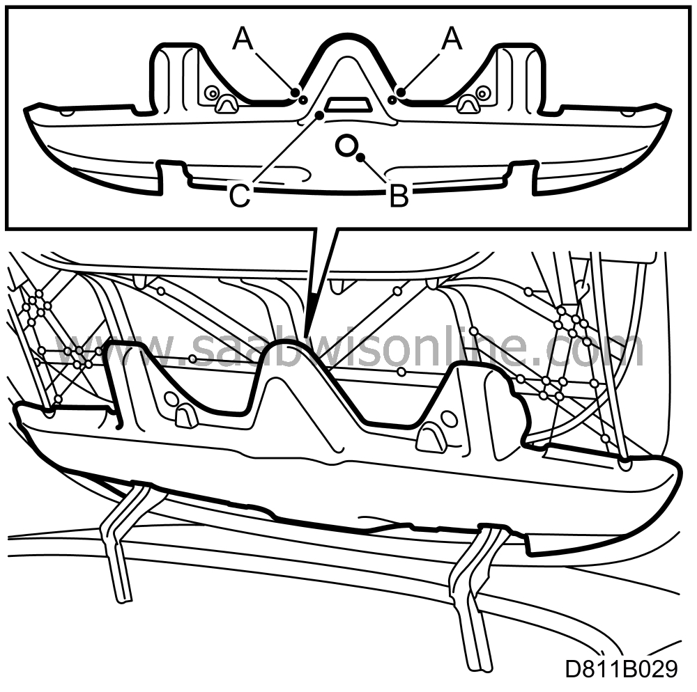
First check whether the top cover panel is fitted with two Torx bolts (A) and that a plastic plug (B) and tape (C) are fitted to the cover panel. If the bolts or plastic plug are not fitted, proceed as described below.
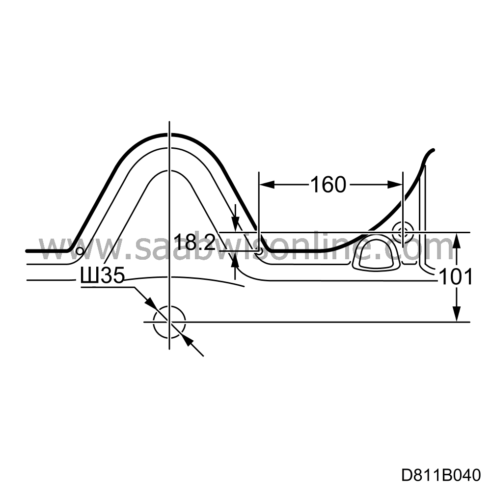
|
1.
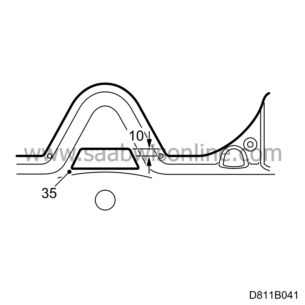
|
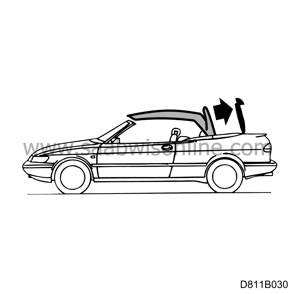
Operate the top so that the fifth bow and top cover are fully up.
|
|
2.
|
Connect ISAT and move the fifth bow locking motor to the half-open position (top cover twist catch in half-open position) using the ISAT commands:
“TSAS”
“ACTIVATE”
“LOCKING MOTOR 5th BOW”
“UP”
|
Important
|
|
This cannot be done unless you have previously changed the control module as described in SI 812-1566.
|
|
|
|
|
3.
|
Protect the rear screen and boot lid. Insert protection under the top cover as the motor can easily drop onto the boot lid.
|
|
4.
|
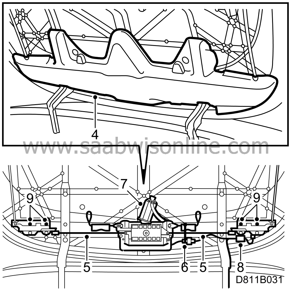
Remove the cover panel.
|
|
5.
|
Remove the locking bars.
|
|
6.
|
Cut the cable tie holding the wiring harness and separate the connector.
|
|
7.
|
Remove the four mounting screws on the locking motor and lift out the motor.
|
|
8.
|
Separate the microswitch connector on the left lock mechanism. Cut the cable tie.
|
|
9.
|
Remove the two lock mechanisms for the fifth bow and place them on a work bench.
|
Important
|
|
It is extremely important to replace the lock washers.
|
|
|
|
|
10.
|
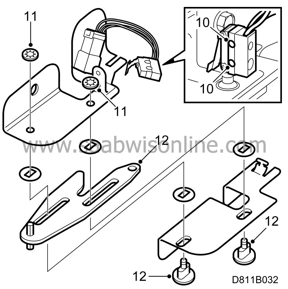
Undo the screws holding the microswitch and remove it.
|
|
11.
|
Undo the lock washers by bending up and cutting with pliers.
|
|
12.
|
Remove the pin and take out the locking tab. Be careful not to lose the plastic washers (4x).
|
|
13.
|
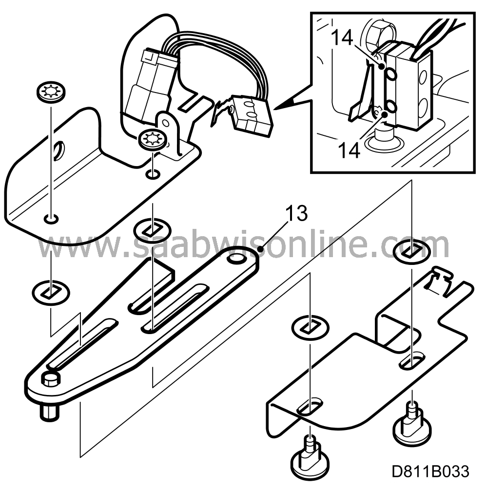
Fit the new locking tab. First insert the two plastic pins in the holder with two oval holes and place two plastic washers on these. Then add the locking tab followed by two plastic washers. Finally add the outer holder and fit the locking washers.
|
Note
|
|
The washers are not held firmly in position after fitting.
|
|
|
14.
|
Screw the microswitch to the holder on the left lock mechanism.
|
|
15.
|
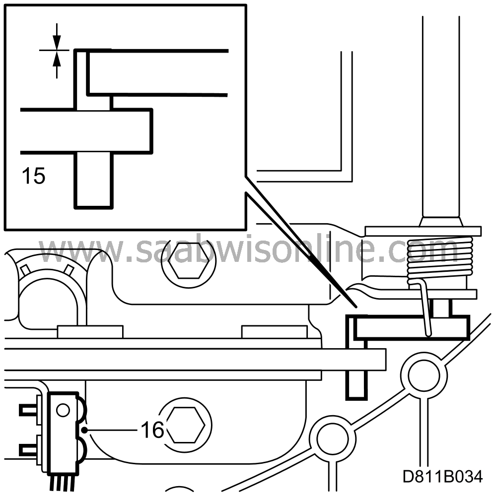
Fit the lock mechanism to the top cover. Ensure that the pin on the locking tab lies against the wire guides for the top cover plate.
|
|
16.
|
Reconnect the connector on the microswitch. Fit a new cable tie.
|
|
17.
|
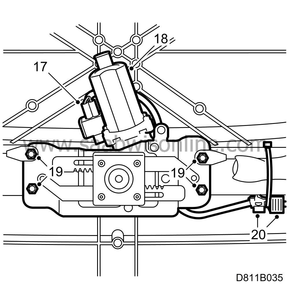
Connect the cable in the parts kit to the new motor.
|
|
18.
|
Place the motor on the top cover. Guide the cable behind the motor holder and out on the left side of the car.
|
|
19.
|
Fit the motor and screw the impact wires to the top bolts of the motor bracket.
|
Note
|
|
The wires should run parallel with the aluminium bar.
|
|
|
20.
|
Connect the motor wires to the car wiring harness and fit a new cable tie around the connector.
|
|
21.
|
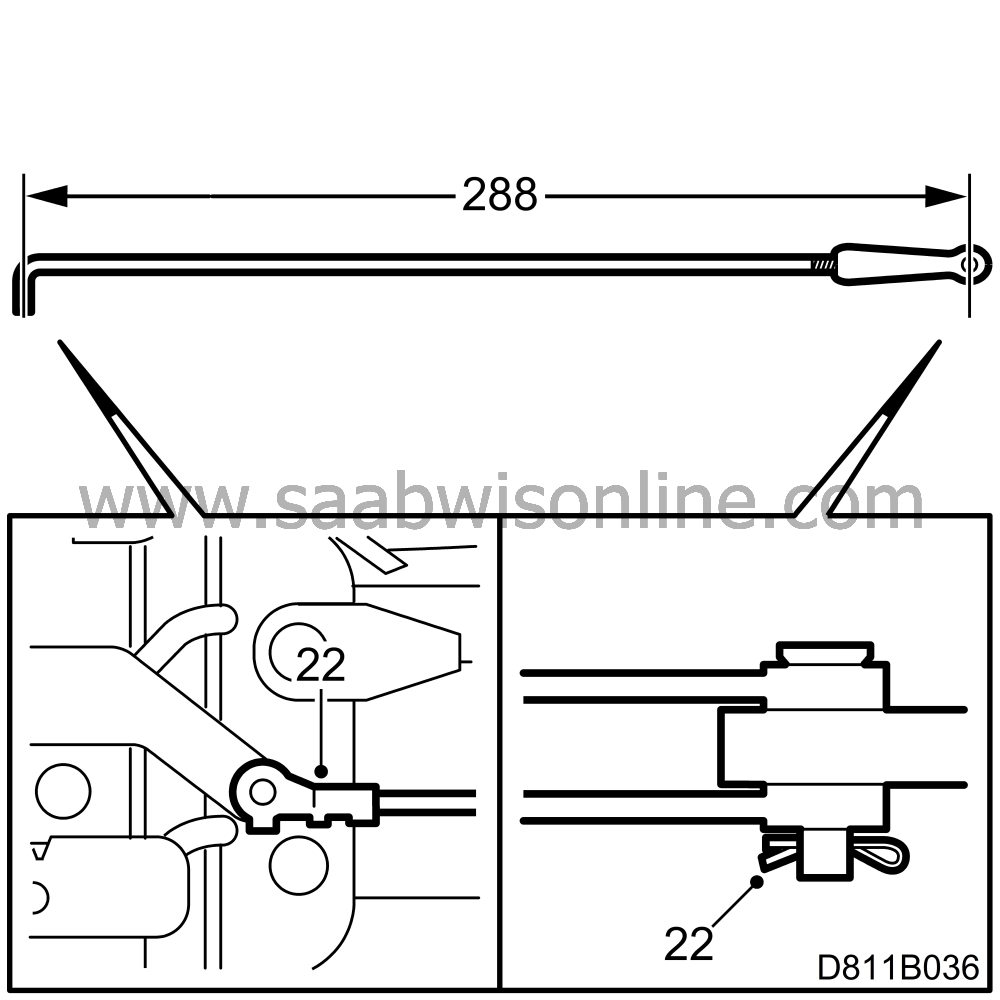
Adjust the length of the locking bars so that these measure
from the centre of the hole for the locking pin to the centre at the other end.
|
|
22.
|
Fit the new locking bars. Use both the old and the new lock washers.
|
|
23.
|
Move the fifth bow locking motor to the open position (top cover twist catch in open position) using the ISAT commands:
“TSAS”
“ACTIVATE”
“LOCKING MOTOR 5th BOW”
“UP”
|
|
24.
|
Check the locking tab in the oval hole for the fifth bow lock. Max. 1.5 mm of the locking tab should be visible.
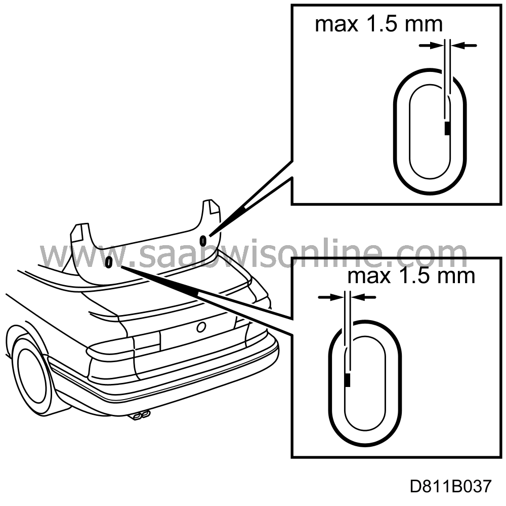
If the adjustment is incorrect and more than 1.5 mm of the locking tab is visible, continue with points 25, 26 and 27.
|
|
25.
|
Move the fifth bow locking motor to the closed position using the ISAT commands:
“TSAS”
“ACTIVATE”
“LOCKING MOTOR 5th BOW”
“DOWN”
|
|
26.
|
Adjust the locking bars by turning to lengthen them.
|
|
27.
|
Repeat points 23 and 24. Then connect the ISAT tool and delete any trouble codes. Remove ISAT.
|
|
28.
|
Move the top up and down 3 times. Check the function.
|
|
29.
|
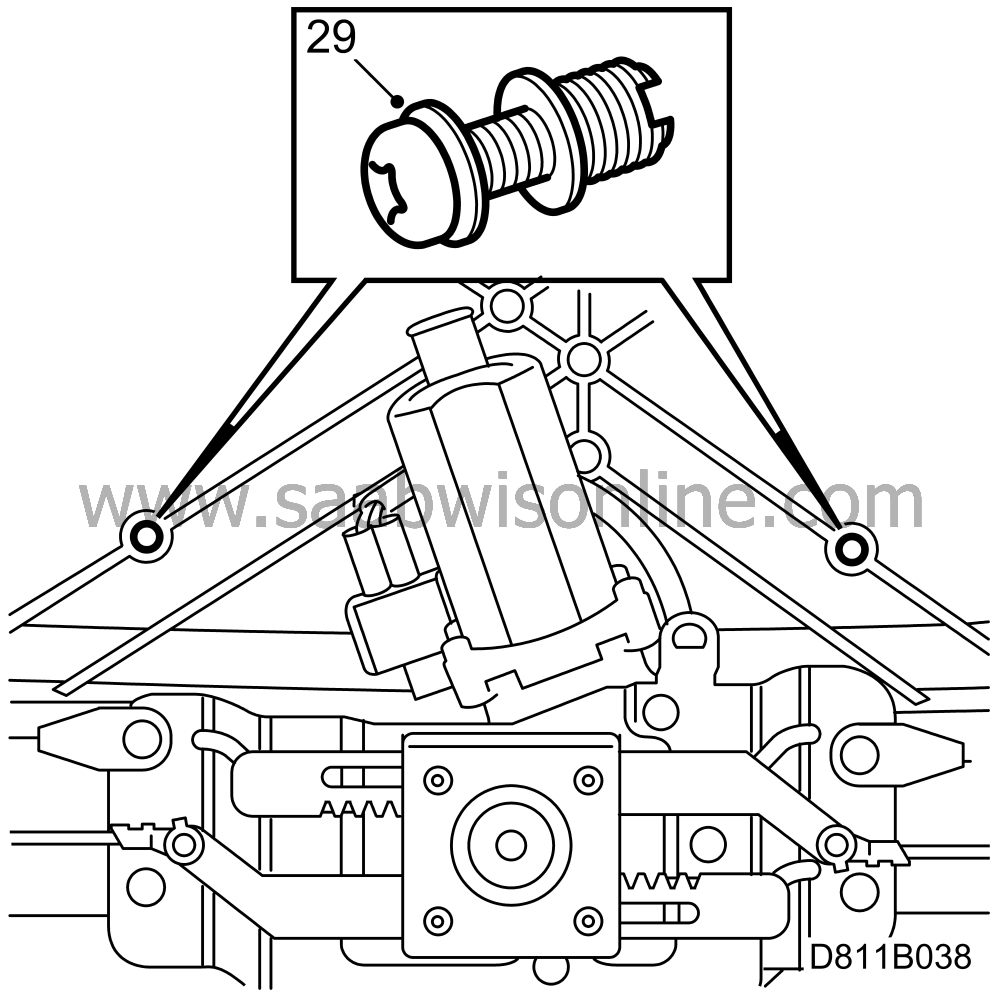
Fit the two threaded inserts. These are fitted into the holes above the fifth bow locking motor. Use Torx bolts and thread into the holes. Tighten to 3 - 4 Nm (2.20 - 2.95 lbf ft) or until they stop against the top cover.
|
Important
|
|
On cars from chassis number V7003161, these threaded inserts are already fitted.
|
|
|
|
|
30.
|
Check that the six clips holding the cover plate are correctly fitted.
|
|
31.
|
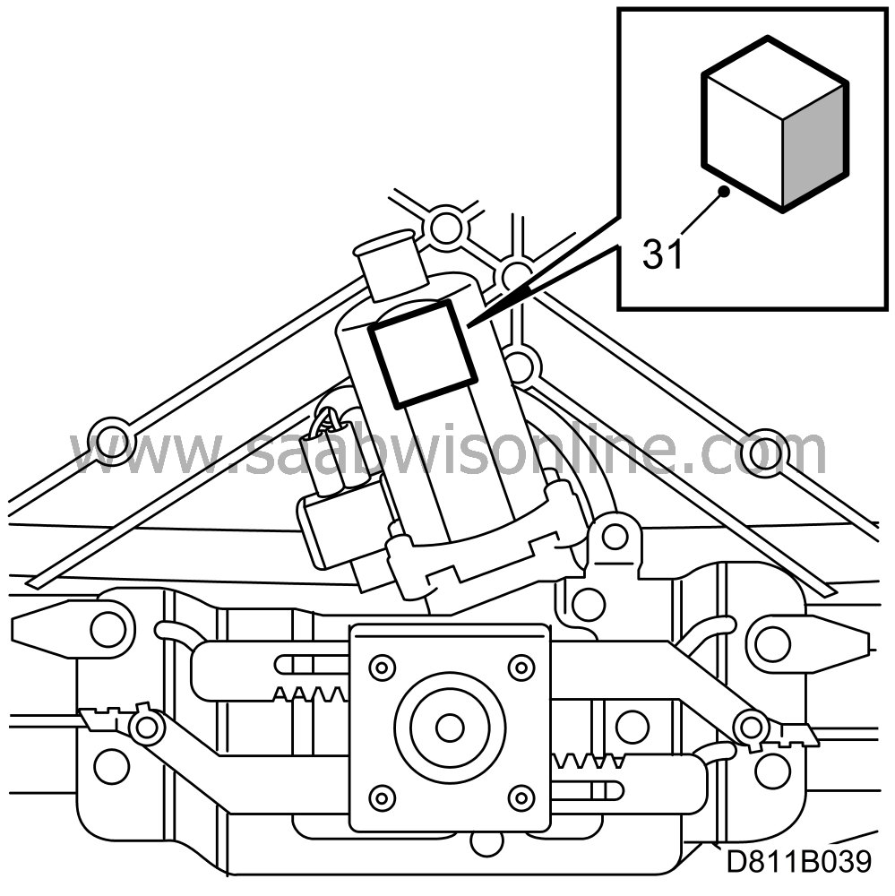
Attach the foam to the flat section of the top of the motor.
|
Note
|
|
Some cars were built prior to VIN Serial No. V7010305 with a new 5th bow latch motor cover but not the 5th bow latch motor.
|
|
On these cars it is not necessary to cut the 35mm hole nor is it necessary to install the plastic plug.
|
|
|
32.
|
To mark the position of the hole on the cover plate, put a spot of paint or grease on the motor shaft.
Press the cover lightly into the clips. Using a bradawl, mark the position of the two holes to be drilled for the threaded inserts.
Press the cover lightly over the motor to mark the shaft position.
Remove the cover and check that the marks match the diagram.
Drill 2 x 6 mm holes for the threaded inserts.
|
|
33.
|
Use a 35 mm hole cutter to cut a hole for the plastic plug.
|
|
34.
|
Deburr the hole and fit the plastic plug.
|
|
35.
|
Remove the protective paper from the tape and fit this to the cover plate. This prevents scratch marks from the fifth bow.
|
|
36.
|
Fit the cover plate. First screw two new bolts into the threaded inserts and then fit the next two bolts. Press in the clips on the cover starting from the centre.
|
|
Standard time information
|
See separate information.


