Principle of operation, throttleposition
| Principle of operation, throttle position |
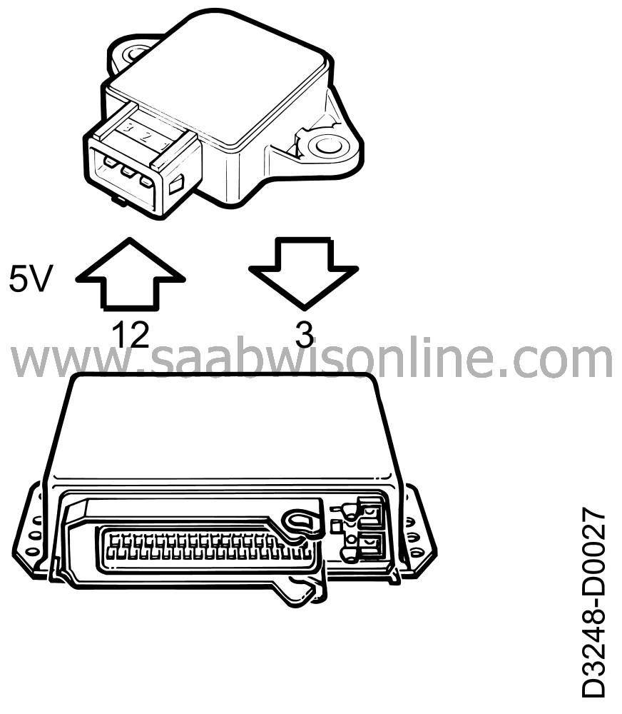
| Throttle position sensor |
The throttle position sensor in the MOTRONIC system consists of a variable resistor (controlled by the position of the throttle butterfly) which regulates the signal level and so supplies the control module with information on the current throttle opening.
Pin 1 of the throttle position sensor receives power (5 V) from pin 12 of the control module.
Pin 2 is grounded through pin 30 of the control module.
Information on the current angle of the throttle is sent from pin 3 of the sensor to pin 53 of the control module. Signal voltage varies between about 0.7 V (idling) and about 4.5 V (full throttle).
In the event of a break in the circuit, the CHECK ENGINE lamp (MIL) lights up and the control module starts to use a preprogrammed signal voltage corresponding to a throttle opening of 31°, causing the idling speed to rise above 1500 rpm.
| Throttle angle |

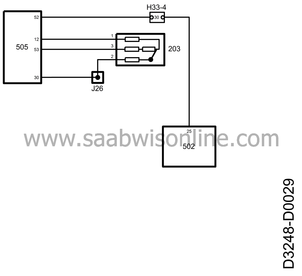
A signal containing information on the current throttle angle goes out from pin 52 of the control module. This information is used by the automatic transmission control module.
The signal is a 100 Hz PWM signal of approx.
| • |
1.3 V at idling speed
|
|
| • |
2.2 V at 2500 rpm (no load)
|
|
| • |
12 V at full throttle.
|
|
This project is supported by memberships and donations. If you use this site, please consider Joining SCNA and/or making a donation.
Our Friends
