PWM measurement
| PWM measurement |
| PWM measurement |
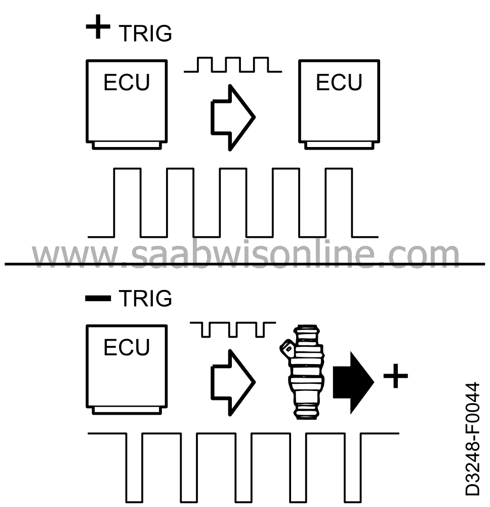
PWM- signals , i.e. communication between control modules, are usually triggered by a positive pulse, i.e. the pulse is a battery+ (positive) pulse. Other PWM outputs (inputs) are usually triggered by a negative pulse. For instance, the injectors are supplied with a constant positive voltage and pulsed by ground (negative) signals from the control module.
| Measurement with a voltmeter |

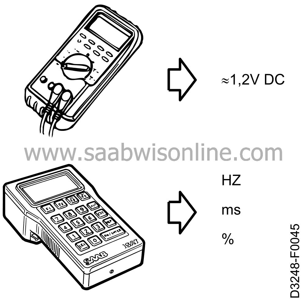
If we measure PWM with a voltmeter, the meter will show the mean voltage applied to the lead so that a higher pulse ratio will give rise to a higher mean voltage. By means of the voltmeter we can roughly estimate the pulse ratio. At a pulse ratio of 9%%a reading of about 1.2 V is usually obtained (0.09 x 13 V = 1.17 V). In the case of PWM triggered by a positive pulse, connect the red test lead to the cable and the black test lead to a good ground.
| Measurement with an ISAT or multimeter with a pulse measuring function |
Connect the red test lead to the cable and the black test lead to a good ground. Then select positive or negative triggering. Frequency, pulse duration and pulse ratio can then be measured.
| Measurement with Logic Probe |

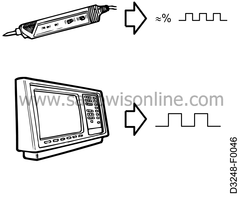
Connect battery+ (positive) supply voltage and a good ground. Then apply the tip of the probe to the cable. The Logic Probe shows the presence of pulses, if any, and gives a rough estimate of the pulse ratio.
| Measurement with an oscilloscope |
Pulse frequency and duration are shown at the same time as we see a picture of the pulses. We see how pulse width changes when the value of the information changes.
| Additional PWM information |
More information about PWM is given in Service Manuals 3:2 and 2:5
 .
.


