B2433. B2434
Symptom: TCS OFF lamp on, TCS symptom inoperative
TCS throttle motor shorted to ground/battery +, no continuity or mechanical
fault
Fault symptom
TCS OFF lamp on, TCS symptom inoperative
Condition
B2433:
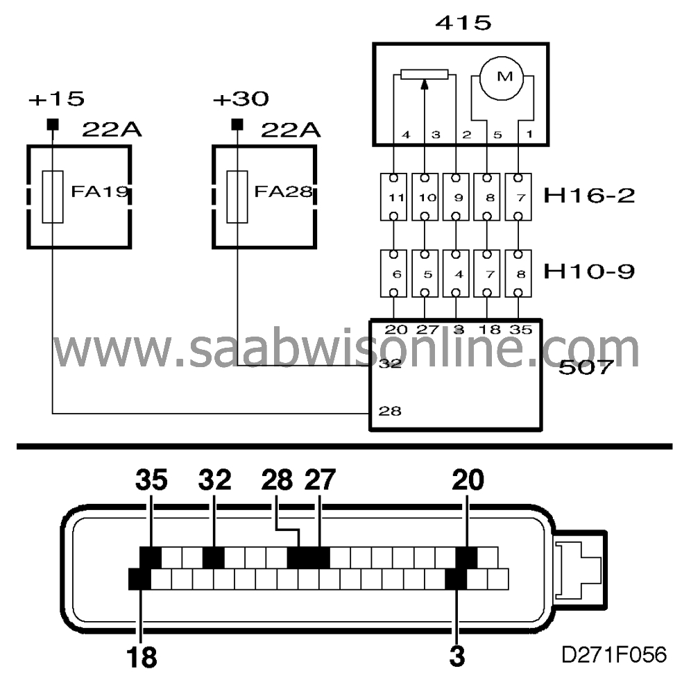
Control module output pin 18 shorted to ground,
battery + or pin 35.
Control module output pin 35 shorted to ground, battery + or pin 18.
B2434:
Control module output pin 18, no
continuity.
Control module output pin 35, no continuity.
Control module input pin 27, no continuity.
Throttle butterfly mechanism or motor binding.
|
Note
|
|
B2434 is generated when the butterfly's "ACTUAL" value does not coincide with
its "REFERENCE" value. This means that the butterfly cannot assume a position calculated by
the control module or that the control module cannot calculate the position of the butterfly.
This could be due to any of three reasons:
|
|
•
|
A mechanical fault, such as a
binding throttle butterfly.
|
|
•
|
An electrical fault, such as a break in the wiring, which prevents the
throttle motor from working.
|
|
•
|
No information received by the control module from the throttle body about the
position of the butterfly, such as no continuity on pin 27 of the control module input.
B2434 can be generated in connection with fault diagnosis when the throttle body wiring
is disconnected and the ignition switch is turned to the Drive
position.
|
Diagnostic procedure - B2433
|
1.
|
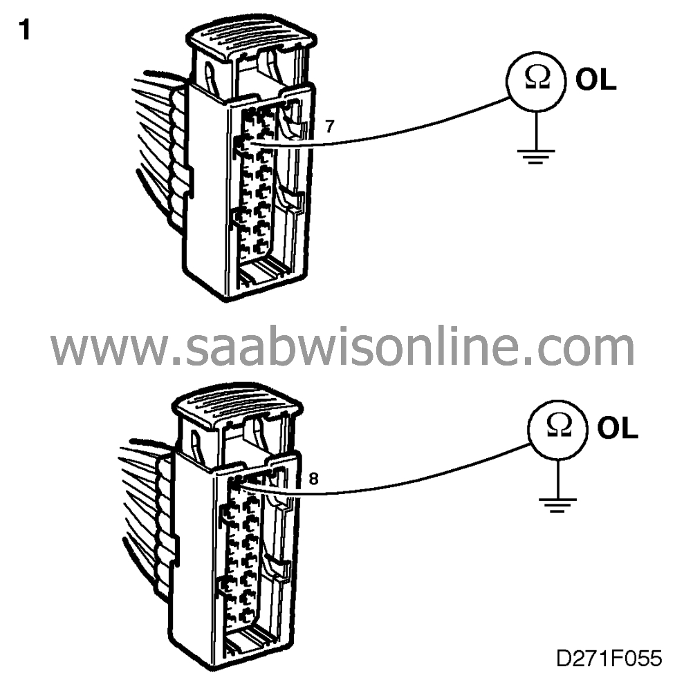
With the ignition
switched off, unplug connector H16-2 and check that the engine is not shorted to ground by
measuring the resistance across ground and pin 7 of the female connector and also across
ground and pin 8 of the female connector.
In both cases the resistance should be infinite (OL).

|
Important
|
|
The throttle motor must never be supplied directly with 12 V.
|
|
|
|
|
2.
|
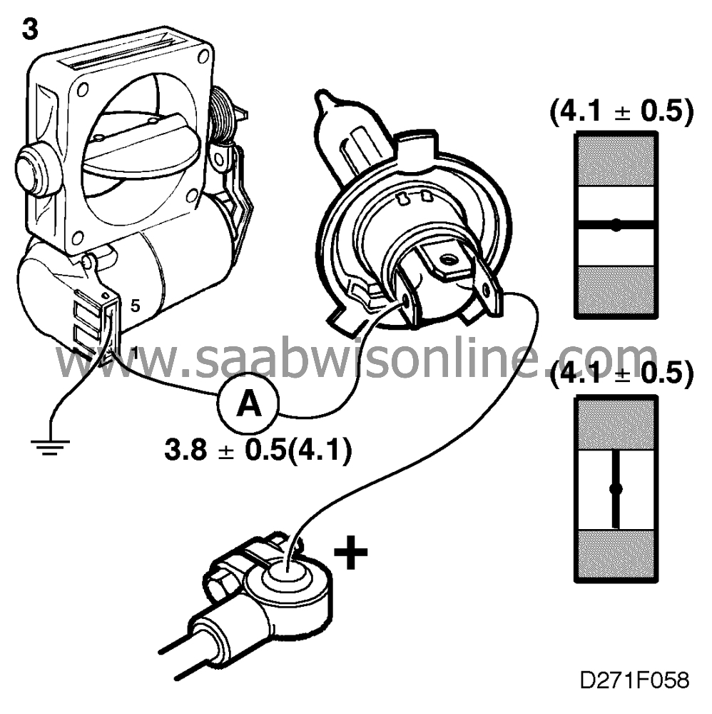
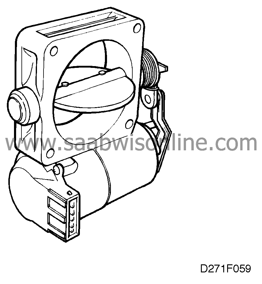
Check the throttle motor electrically and mechanically by connecting it to the car
battery in series with the high- beam filament of a 12V/60W bulb (H4). Using a multimeter set
for measuring current in the 10A range, a reading of 3.8 ± 0.5 A should be obtained.
Slowly change the position of the butterfly by hand from open to closed. The meter reading
should now vary by a maximum of ± 0.5 A from the reading first obtained.
Also check that it is noticeably harder to close the butterfly when the throttle motor is
supplied with current.
If the above checks out OK, proceed to point 4. If not, continue with point 3.
|
|
4.
|
With the ignition switched off, plug a BOB into the TCS control
module
connector (control module not connected). Check the cable between pin 18 of the control
module connector and pin 8 of the male connector (H16-2) for
continuity/shorting.
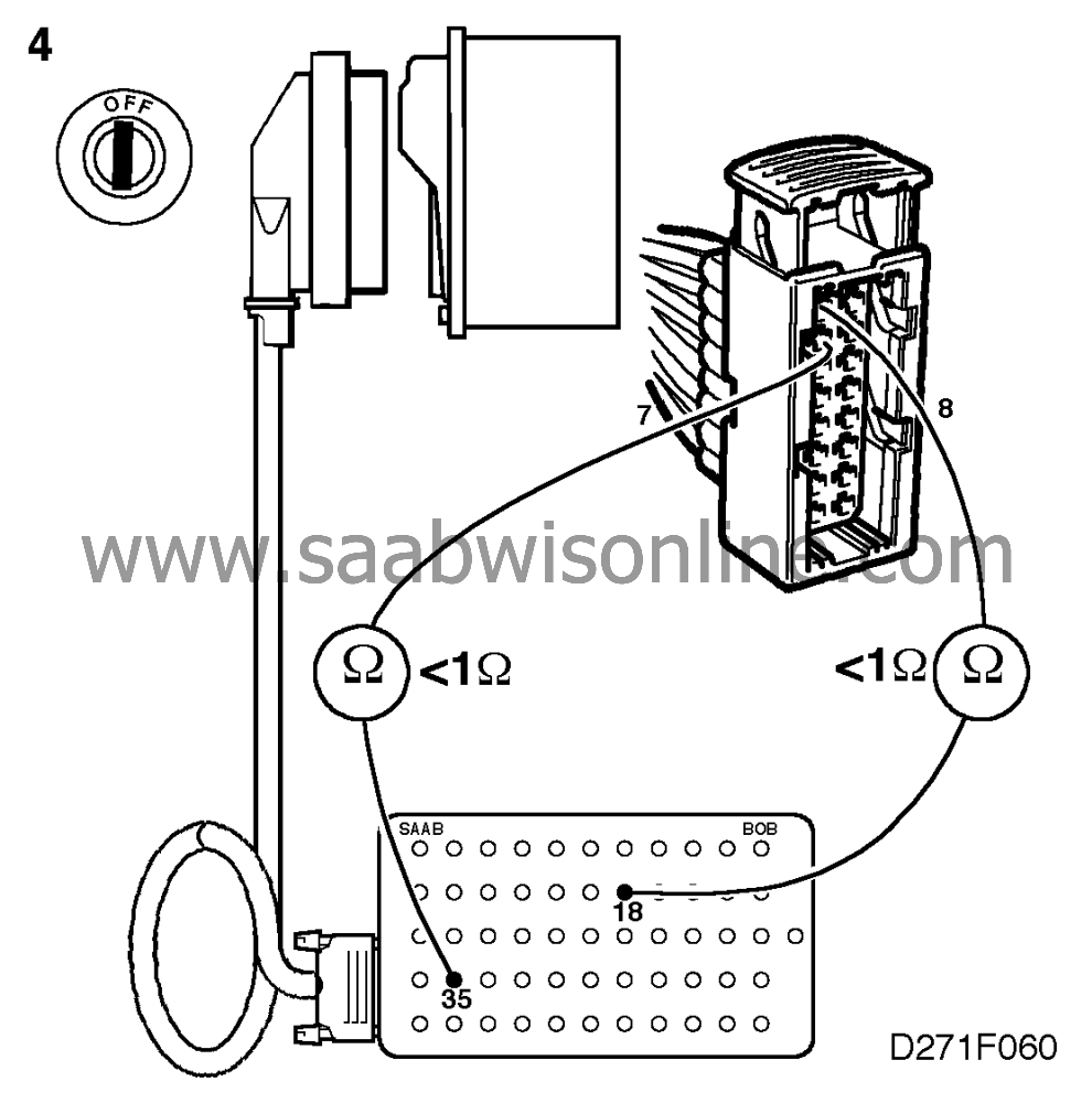
Also check the cable between pin 35 of the control module connector and pin 7 of the
male connector for continuity/shorting.
|
|
5.
|
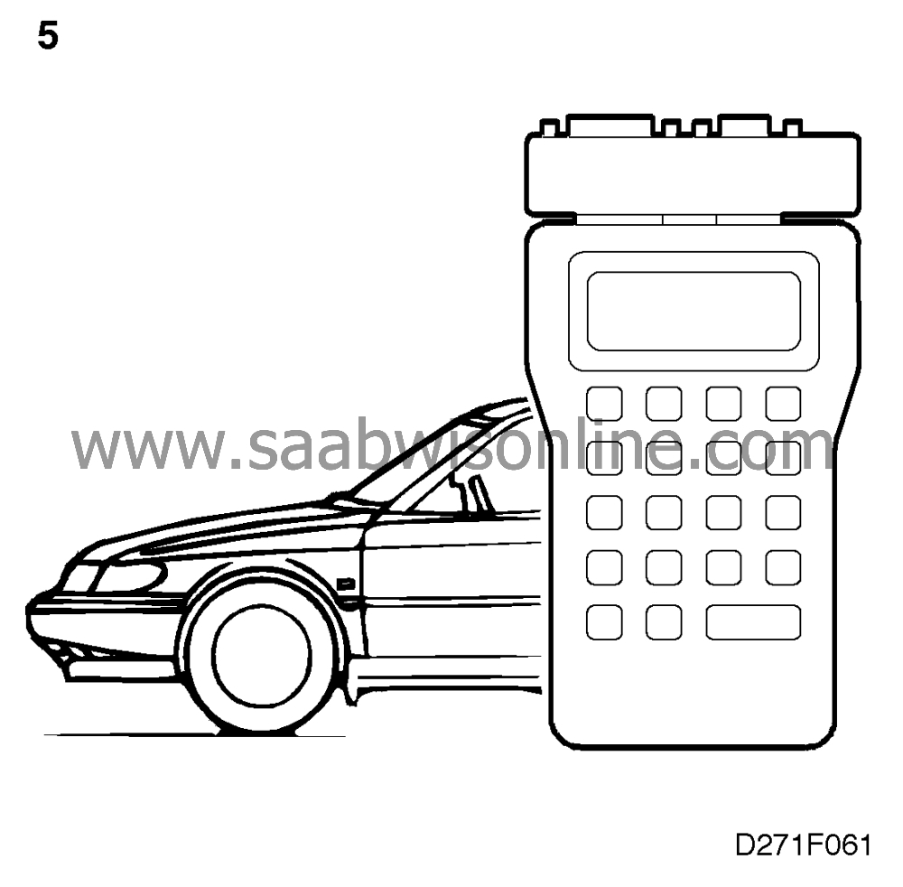
Clear the code diagnostic trouble code. Start the car and drive it on test
to check whether the diagnostic trouble code recurs. If it does, see "Before replacing a control
module" for further measures.
|
Diagnostic procedure - B2434
|
1.
|
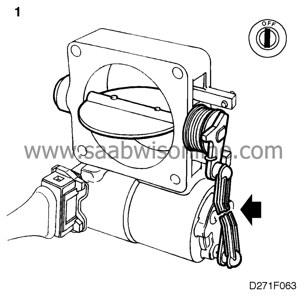
With the ignition
switched off, check that the throttle butterfly can easily be moved to the closed position by
hand and that no binding occurs. The force of the spring should also return it to the open
position with ease. If it is in proper working order, proceed to point 2. If it is not, remedy the
fault if possible or fit a replacement throttle body.
|
|
2.
|
Connect the ISAT. With the ignition in the Drive position, open the TCS
throttle butterfly halfway by hand. Then select "BUTTERFLY CLOSING ON" in the
"ACTIVATE" menu.

|
Note
|
|
If the actuator motor rotates the TCS throttle butterfly towards the
open
position when "BUTTERFLY CLOSING ON" is activated, it is because
the control module receives no information about the position of the butterfly on input pin 27.
|
|
If the butterfly
either
closes
or
opens, proceed to point 4. If it does not, continue with point 3.
|
|
|
3.
|
Carry out the measures described under diagnostic trouble code B2433.
|
|
4.
|
Carry out the measures described under diagnostic trouble codes B1302 and
B1303.
|
