TCS fault diagnosis schedule
|
|
TCS fault diagnosis schedule
|
|
Points to note when diagnosing faults
|
It is impossible to give any general rules for the procedure to follow when diagnosing
faults in each individual case. Depending on the fault symptoms and other information
available, one method may be the best in some situations and another method best in
others.
However, the following points may serve as guidance when carrying out fault diagnosis
on the TCS system and it might be helpful to recall this information from time to time as the
work progresses.
|
1.
|
Always begin by using an ISAT
to obtain a readout of the diagnostic trouble codes, if any. In some fault diagnosis procedures,
electric wiring is
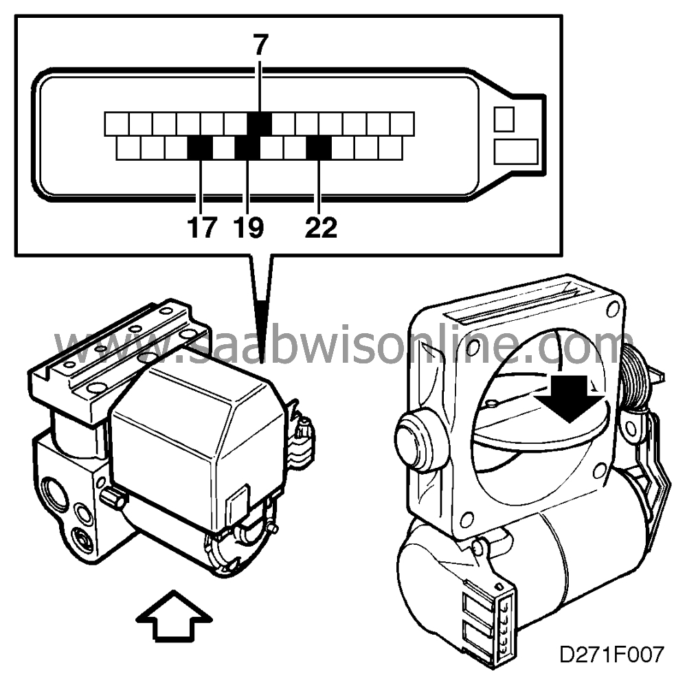
disconnected while the ignition is switched on or the TCS throttle butterfly is moved out of its
normal position. This gives rise to the generation of diagnostic trouble codes. Therefore, when
the work is finished, always clear any such trouble codes that may have been generated.
|
|
2.
|
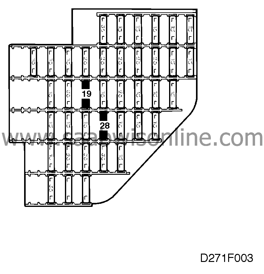
Check fuses 19 and 28.

|
|
3.
|
Inspect connectors, particularly H16-2, for corrosion on pins and contact
surfaces, excessive play, looseness or anything else which may be the cause of poor contact
or a deterioration in conductivity.

If problems due to poor contact are suspected, spray CONTACT 61 (part No. 45-300 45
20) on female connectors.
|
|
4.
|
Before connecting a BOB into circuit, first check the voltage supply to
pins 28 and 32 and make sure that pins 13 and 30 are properly grounded.

|
|
5.
|
Always start fault diagnosis in the ABS system if the ANTI LOCK lamp is
alight.

|
|
6.
|
With the ignition switched off, check that the throttle butterfly can be
moved to the closed position without obstruction or binding and that the spring returns it to the
open position with ease.

|
Important
|
|
For communication between the ISAT and the TCS control module to be possible,
|
|
• the ignition switch must be in the Drive position
|
|
• engine speed must be <1500 rpm (if the engine is running)
|
|
• the TCS must be contacted.
|
|
The ISAT has no contact with the system if:
|
|
• the circuit to pin 9 of the control module is defective
|
|
• the ground connection on pins 13 and 30 is not correct
|
|
• the voltage supply on pins 28 and 32 is not correct
|
|
• the circuit to pin 3 is shorted to battery +.
|
|
|
|


