P0105,P0106, P0107, P0108
Symptom: The CHECK ENGINE lamp (MIL) is on. Impaired driveability. Basic boost
pressure only. Possible existence of other DTCs (misfiring, closed loop, boost pressure
control). The A/C compressor does not work. The turbo/APC gauge gives implausible
readings.
|
|
P0105
,
P0106
,
P0107
,
P0108
|
Manifold absolute pressure sensor
Symptom of fault
The CHECK ENGINE lamp (MIL) is on. Impaired driveability. Basic boost
pressure only. Possible existence of other DTCs (misfiring, closed loop, boost pressure
control). The A/C compressor does not work. The turbo/APC gauge gives implausible
readings.
Conditions
P0105: All-embracing DTC
P0106: <50 kPa or >140 kPa when the ignition switch is turned to the ON position
or when the engine is running and the pressure is constant for 60 seconds despite throttle
position changes.
P0107: Ignition switch in the ON position: <10 kPa for 2 seconds at wide throttle
opening.
P0108: Ignition switch in the ON position: >245 kPa for 2 seconds at slight throttle
opening
Diagnostic help
|
•
|
The turbo/APC gauge is electric
and shows the pressure sensor value
|
|
•
|
The pressure sensor reading can be obtained on an ISAT scan tool. Turn the
ignition switch to the ON position and then back to the OFF position.
|
|
-
|
Connect an ISAT scan
tool.
|
|
-
|
Select
"READ FUNCTIONS".
|
|
-
|
Select
"INTAKE PRESSURE".
The ISAT scan tool should show a reading of about 102 kPa (NOTE: the reading
is dependent on air pressure).
|
|
-
|
Engine running at idling speed.
|
If the pressure sensor is in perfect working order the reading obtained on the
ISAT scan tool should be 40-60 kPa.
Checking the wiring. Intermittent faults may occur as a result of occasional short circuits
and breaks in the wiring. Jiggle the leads and in-line connectors at several places and in
different directions to reveal faults in the wiring harness. Observe the multimeter, ISAT scan
tool or test lamp while carrying out this check.
Diagnostic procedure
1. Check the vacuum hose
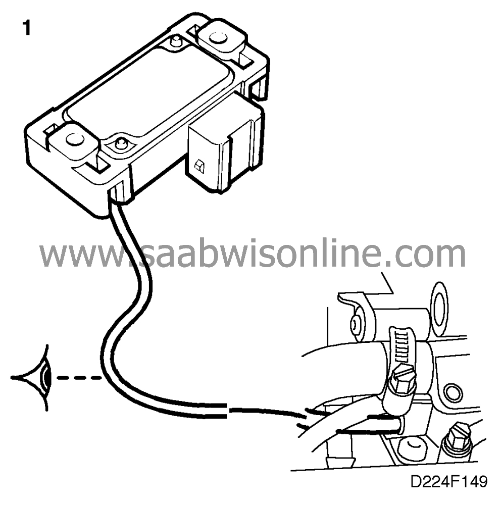
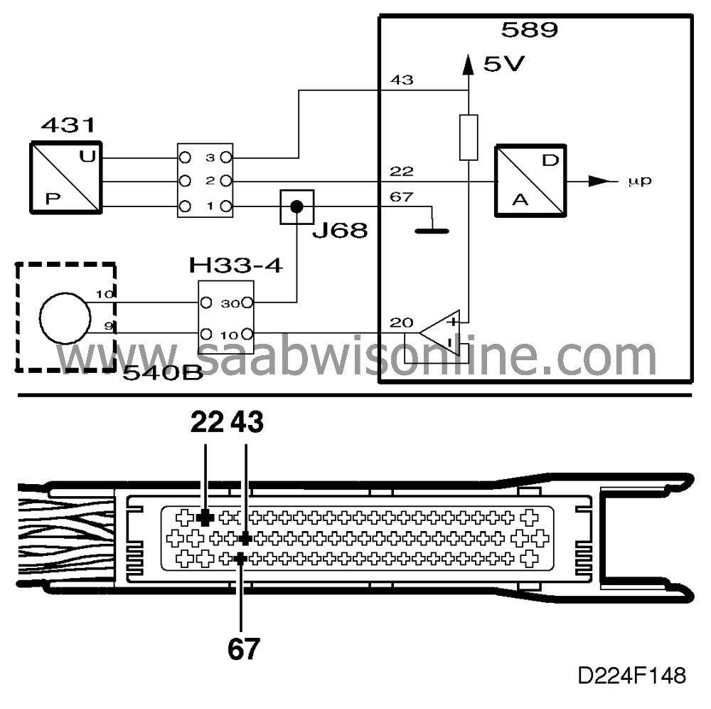 Inspect the vacuum hose between the pressure sensor and intake manifold for
breaks, leakage, pinching or clogging.
Is the vacuum hose OK?
Continue with point 2.
Rectify the fault and proceed to point 4.
2. Check the pressure sensor's ground connection and power
supply
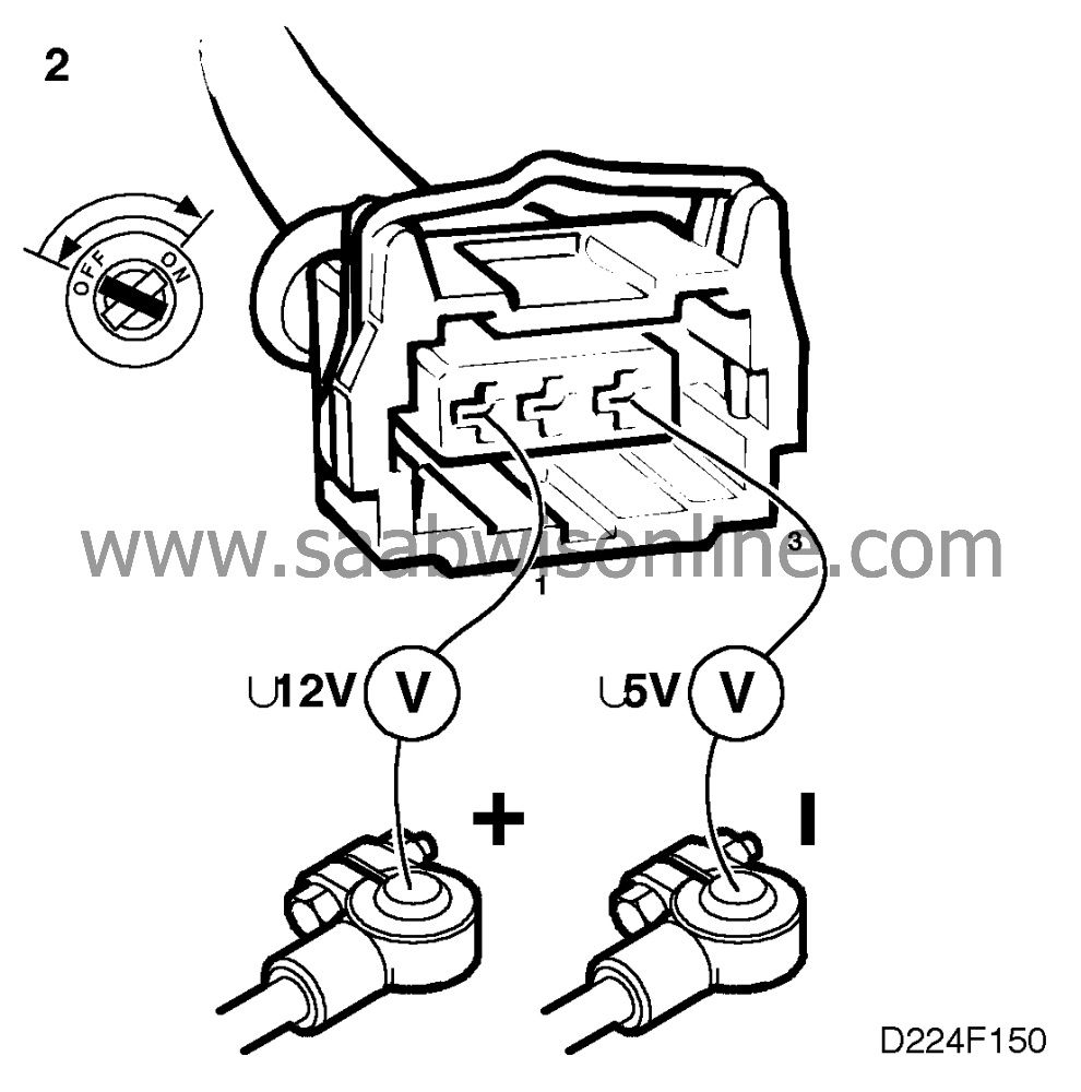
|
-
|
Turn the ignition switch to the ON
position and then back to the OFF position.
|
|
-
|
Unplug the pressure
sensor's 3-pin connector.
|
|
-
|
Take voltage readings in the
connector across:
• pin 3 and B-
__________ar;_____ (about 5 V)
• B+ and pin 1______ about 12
V
|
Are all readings OK?
Continue with point 3.
Rectify the lead in question and proceed to point 4.
3. Check the electronic control module's
pressure sensor input
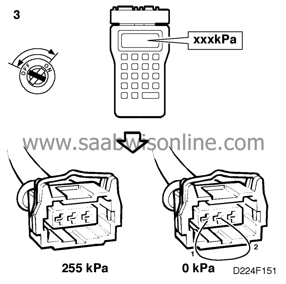
|
-
|
Turn the ignition switch to the ON
position and then back to the OFF position
|
|
-
|
Unplug the pressure
sensor's 3-pin connector.
|
|
-
|
Connect an ISAT scan tool. Select
"READ FUNCTIONS". Select
"INTAKE PRESSURE".
|
The ISAT scan tool reading should be 255 kPa.
|
-
|
Connect a jumper lead between
pins 2 and 1 of the pressure sensor connector.
|
The ISAT scan tool reading should be 0 kPa.
Are all readings OK?
Change the pressure sensor and continue with point 4.
Rectify the lead in question and proceed to point
4.
4. Final check
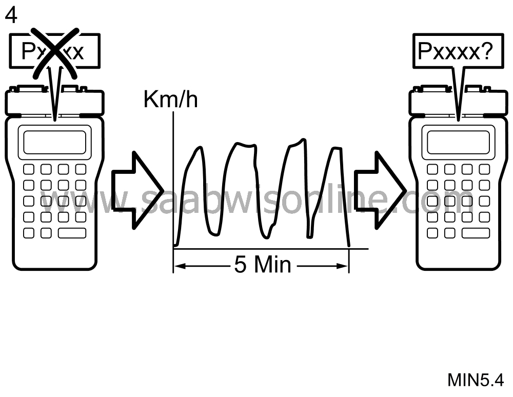
|
-
|
Clear the diagnostic trouble code.
|
|
-
|
Implementation of driving cycle:
Drive the car at varying engine rpm and loads for 5 minutes.
|
|
-
|
Evaluation of driving cycle: Check
whether the diagnostic trouble code has recurred.
|
Has the diagnostic trouble code recurred?
Proceed to
 .
.
The remedial measure taken was correct.


