Ignition
Symptom of fault
Engine will not start.
Diagnostic procedure
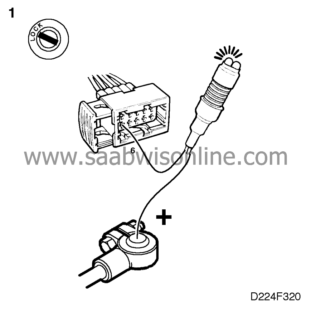
1. Check the ignition discharge module's ground
connection


|
-
|
Connect a test lamp to battery
positive (B+) and pin 6 of the ignition discharge module's connector.
|
The test lamp should light up.
Is the test lamp on?
Continue with point 2.
Check and rectify the wiring, including grounding point G7P. Then continue
with point 4.
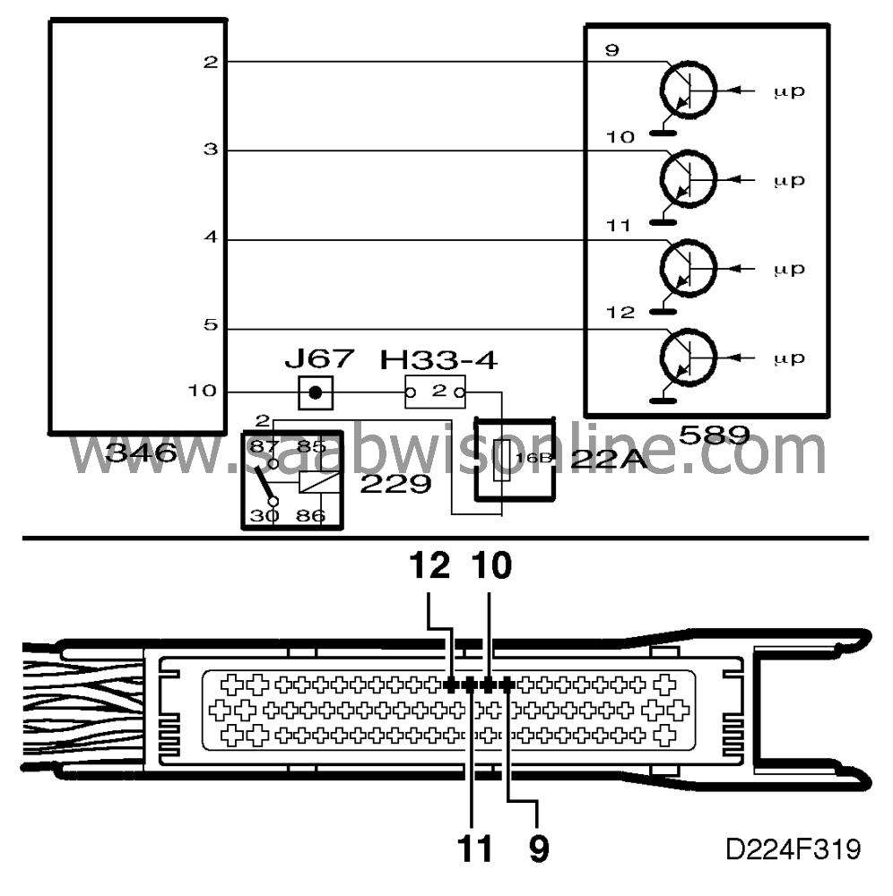
2. Check the ignition discharge module's 12 V
supply

|
-
|
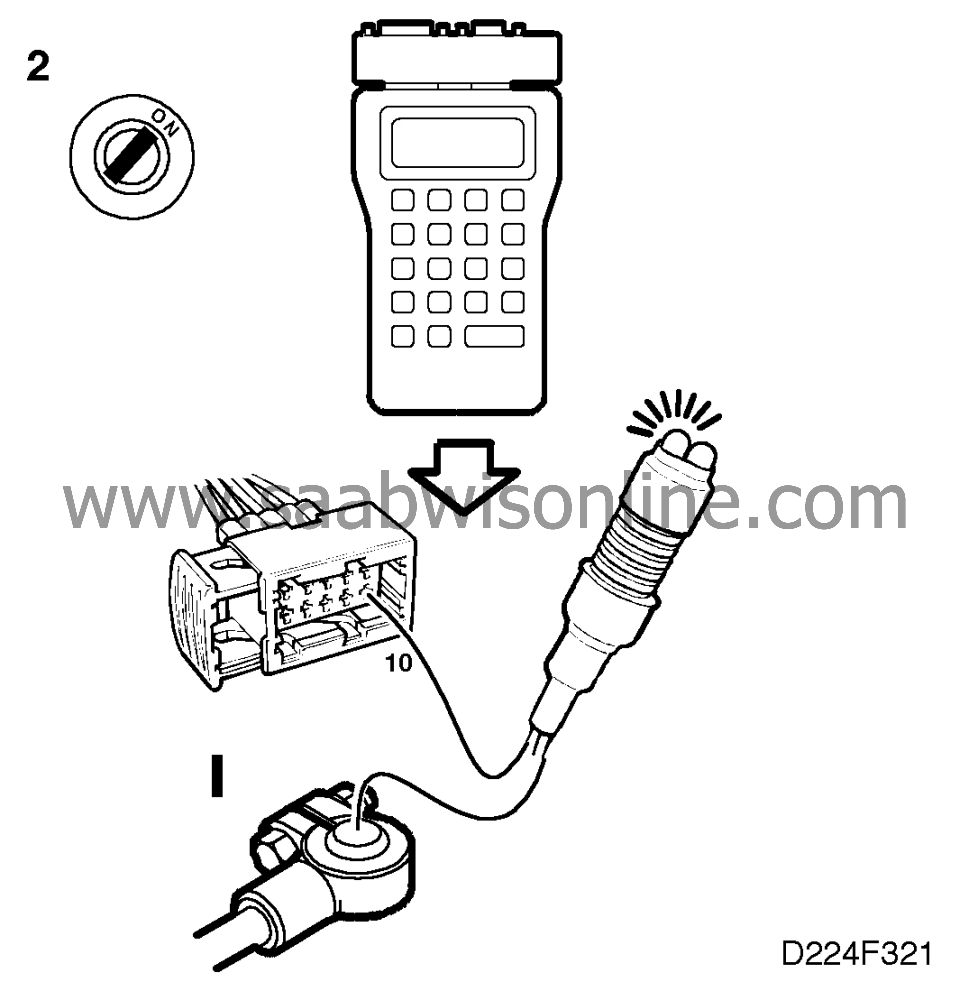
Connect the test lamp to pin 10 of
the ignition discharge module's connector and B-.
|
|
-
|
Activate one of the ignition coils by
means of the ISAT scan tool. The purpose of this is to cause the main relay to operate.
|
The test lamp should light up.
Does the test lamp light up?
Continue with point 3.
Continue as described in
 .
.
 Warning
|
|
The electronic ignition system generates up to 40,000 Volts. Such voltages can prove
fatal to people with weak hearts or those who are fitted with a pacemaker. All due caution
should therefore be observed when carrying out any work involving the ignition
system.
|
|
|
|
|
|
|
Important
|
|
The ignition discharge module must be positioned with the ignition coils facing down
during the test so that the transformer oil will provide good insulation in the high-voltage part of
the ignition coils.
|
|
|
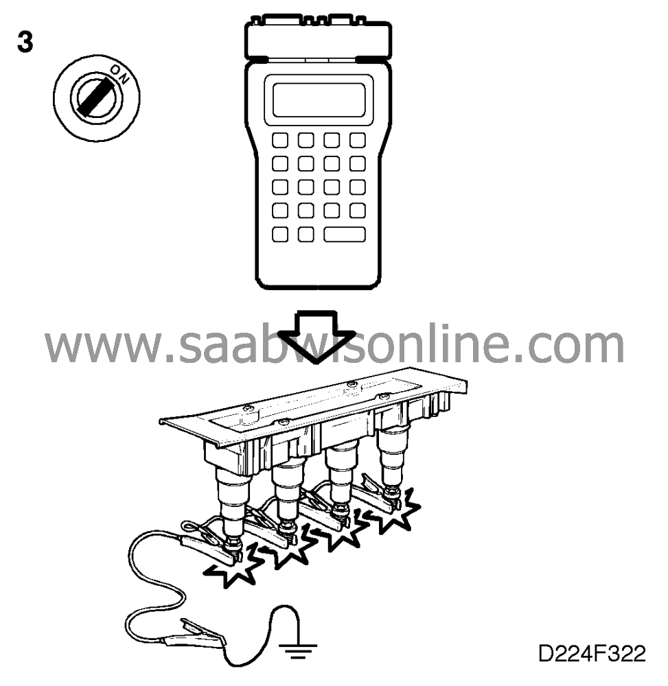
3. Check the operation of the ignition discharge
module

|
-
|
Remove the ignition discharge
module from the camshaft cover.
|
|
-
|
Fit test spark plugs (part No. 86 11
386) in the ignition discharge module.
|
|
-
|
Ground the spark plugs using test
cable 86 10 867.
|
|
-
|
Activate each separate ignition coil,
using the ISAT scan tool.
|
Sparks should be produced on each spark plug that is activated.
Are sparks obtained?
Change the spark plugs and continue with point 4.
Change the ignition discharge module and proceed to point 4.
4. Final check

|
-
|
Try to start the
engine.
|
Did the engine start?
The remedial measure taken was correct.
The fault is not in the ignition system.


 Warning

