Ignition discharge module
| Ignition discharge module |
Ignition
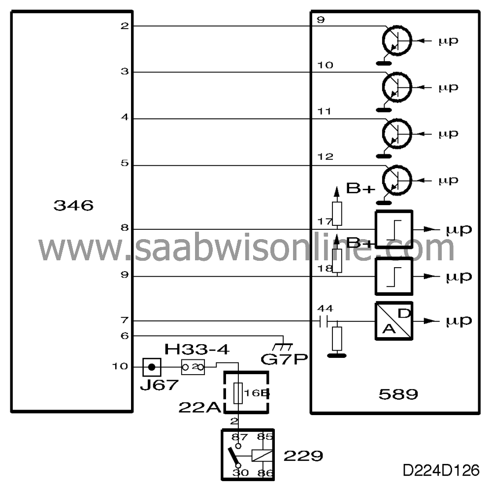
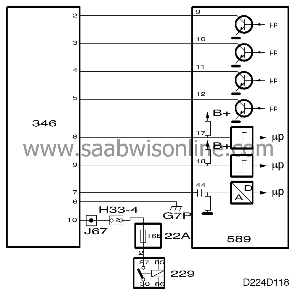
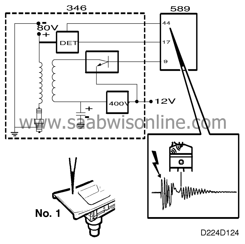
The ignition discharge module is mounted on the camshaft cover over the spark plugs. There are 4 ignition coils in the ignition discharge module, the secondary windings of which are connected directly to the spark plugs.The ignition discharge module is supplied with power (B+) from the main relay and connected to ground at grounding point G7P.
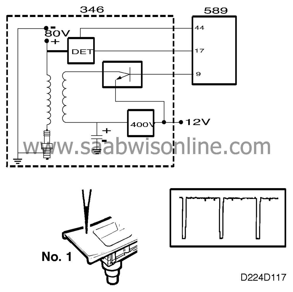
When the main relay operates, power (B+) is supplied to the ignition discharge module which converts 12 V to 400 V d.c. and charges a capacitor with it. This voltage (400 V) is connected to one pole of the primary windings of the 4 ignition coils.
Four trigger leads are connected to the ignition discharge module from Trionic ECM pin 9 (cyl. 1), pin 10 (cyl. 2), pin 11 (cyl. 3) and pin 12 (cyl. 4).
When the engine control module grounds pin 9, the other pole of the primary winding of the ignition coil for cylinder 1 will be grounded (via the B+ input of the ignition discharge module) and the 400 V transformed to a maximum of 40 V. Ignition for cylinders 2, 3 and 4 takes place in the same way.
If there is an open circuit in the power supply or a ground connection to the ignition discharge module, the engine will not start.
Ignition control
On starting, ignition timing is 10° BTDC. To facilitate starting when the coolant temperature is below 0°C, the electronic control module will ground the relevant trigger lead 210 times a second from 10° BTDC to 20 ATDC, which gives rise to the "multispark" function. This function is discontinued at engine speeds above 900 rpm.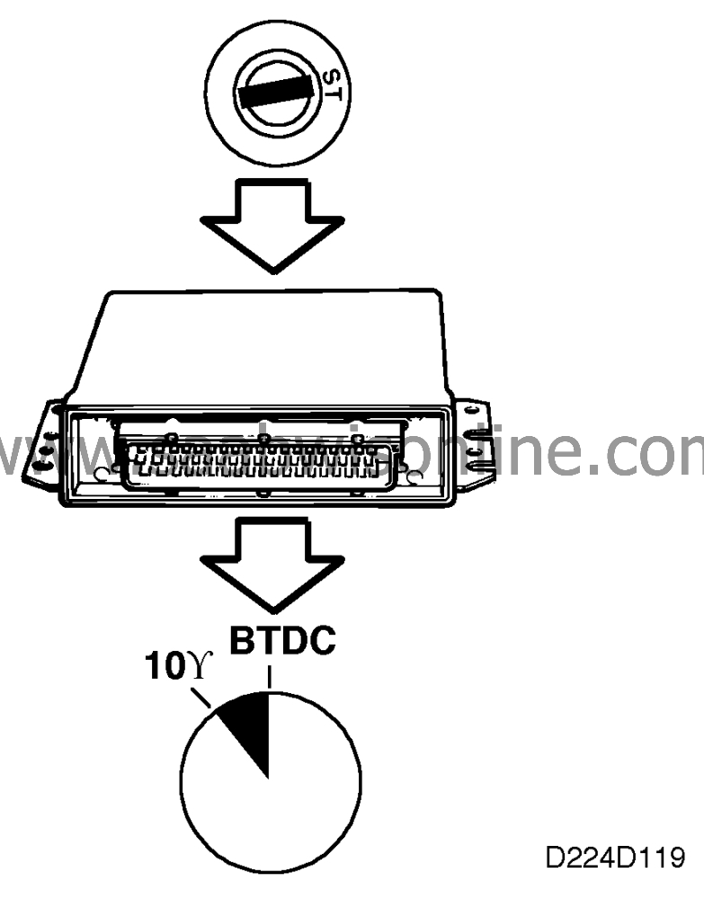
A special ignition control curve is used at idling speed. Normal ignition advance is about 6-8°.
If engine speed drops, as may happen when the radiator fan cuts in, the ignition timing will be advanced to a maximum of 20° BTDC to increase engine torque and restore engine revs. Similarly, the ignition will be retarded if engine speed increases.
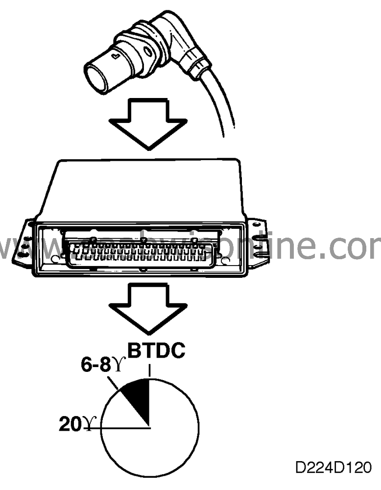
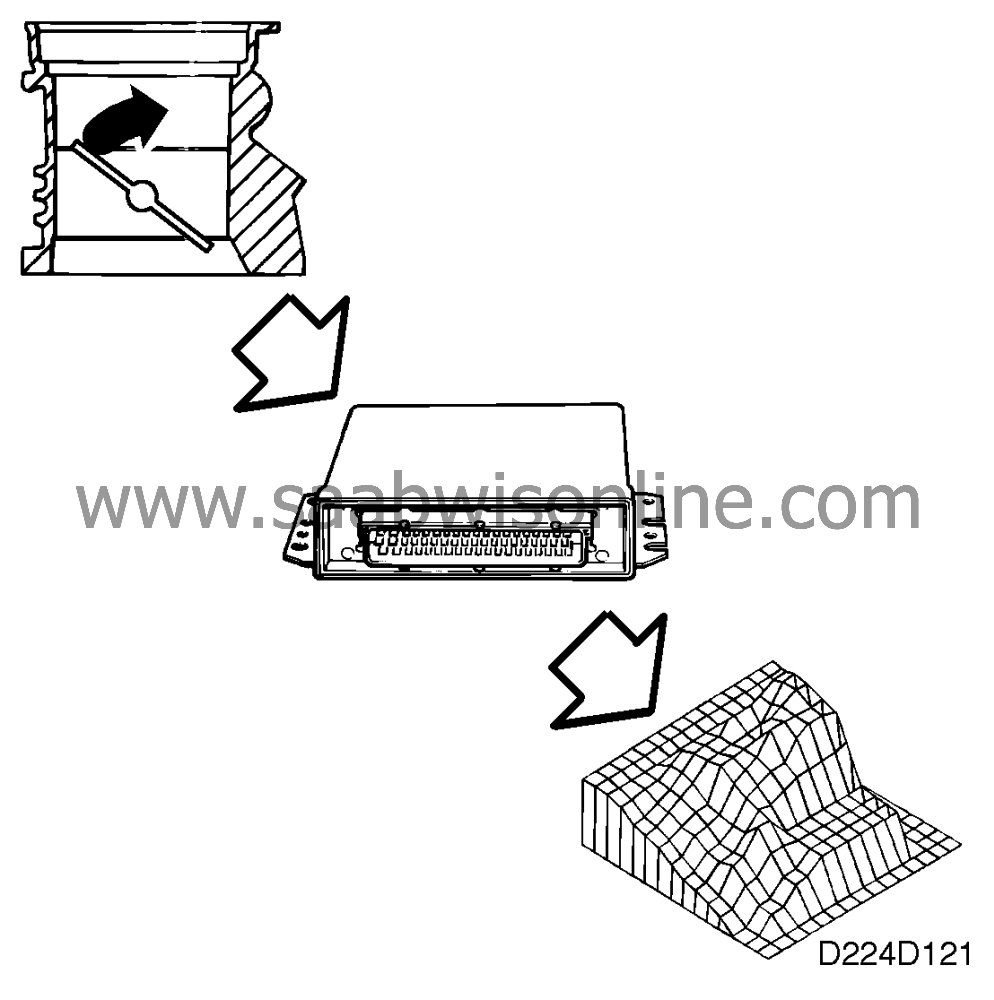
Ignition control during idling compensates for rapid changes in engine idling speed.
When the throttle position moves away from idling, ignition control changes over to normal control depending on load and engine speed.
Combustion signals
The Trionic system does not have a camshaft position sensor. A camshaft position sensor is normally required for sequential knock control and fuel injection.The Saab Trionic must decide whether cyl. 1 or cyl. 4 is firing when the crankshaft position sensor indicates that cyl. 1 and cyl. 4 are at top dead centre.
This is done as follows: One of the poles of the secondary windings of the 4 ignition coils is connected in the usual manner to the spark plugs. The other pole is not connected directly to ground but to 80 V. As a result, 80 V is always present across the spark plug electrodes except at the very moment a spark is produced.
When combustion takes place, the temperature in the combustion chamber is very high. The gases are ionized and start to conduct current. This means that a current passes across the spark plug gap (without producing a spark).
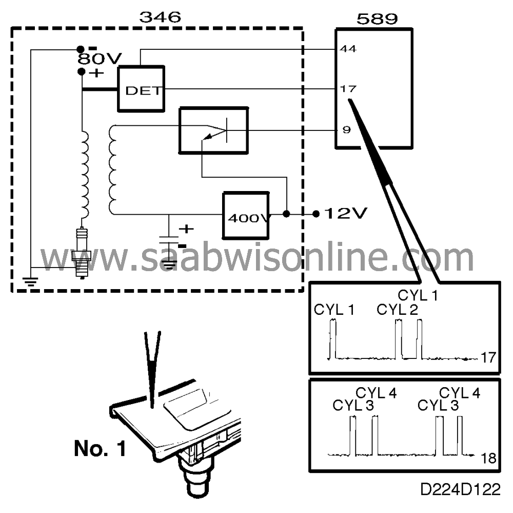
The ionization current is measured in pairs, cylinders 1+2 and cylinders 3+4. If combustion takes place in cylinder 1 or 2, the ignition discharge module sends a pulse (B+) to pin 17 of the Trionic's engine control module. Similarly, the ignition discharge module sends a pulse (B+) to pin 18 of the engine control module if combustion takes place in cylinder 3 or 4.
If the crankshaft position sensor indicates that cylinders 1 and 4 are at top dead centre and a pulse (B+) is applied to pin 17 of the engine control module at the same time, then the engine control module knows that cylinder 1 has fired.
When the engine is started, the ECM does not know which of cylinders 1 and 4 is in the compression position, and ignition consequently takes place on both cylinders 1 and 4 simultaneously. In the same way ignition takes place on cylinders 2 and 3. As soon as combustion signals arrive on pins 17 and 18 of the ECM, both ignition and fuel injection are synchronized to the engine firing order.
On M96 and later models (On-Board Diagnostic II), combustion signals are also used to detect misfiring.
In the event of an open circuit in either of the leads connected to pins 17 and 18 of the electronic control module, no synchronization of ignition timing or fuel injection will occur. Knock control will take place at the same time on cylinders 1+4 and 2+3.

Knock control
The Saab Trionic does not have a conventional knock sensor. Instead the ignition discharge module analyzes the ionization currents for all the cylinders and sends signals to pin 44 on the Trionic ECM. This function is adaptive with respect to upsetting fuel additives.From the combustion signals the engine control module knows which cylinder has fired and if at the same time the knocking signal is above a definite level, the control module records knocking on that cylinder. The ignition timing is then retarded 1.5 5 on that cylinder.
In the event of persistent knocking, the timing will be retarded additionally but not more than a maximum of 12 5 . If ignition timing is retarded by more than a certain amount on all cylinders, the quantity of fuel injected will be slightly increased.
If knocking occurs when intake manifold pressure is higher than about 140 kPa, knock control will take place in a different way, as follows: first the fuel injection and ignition matrices are changed and if this does not help then boost pressure will be reduced.
The aim is to achieve good performance even in the event of knocking.
In the event of a break in the lead connected to pin 44 of the electronic control module, basic boost pressure will be obtained and ignition timing retarded by 12 when the engine load is so high that knocking could occur.
Burn-off
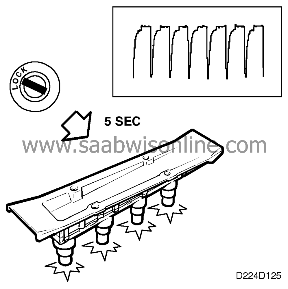
After the ignition switch has been turned off and the engine has stopped, the main relay remains activated for a further 6 seconds. The Trionic ECM then grounds all the trigger leads 210 times per second for 5 seconds. Each electrode gap burns off impurities with more than 1000 sparks.