Wiring diagram, Saab Trionic (III)
| Wiring diagram, Saab Trionic (III) |
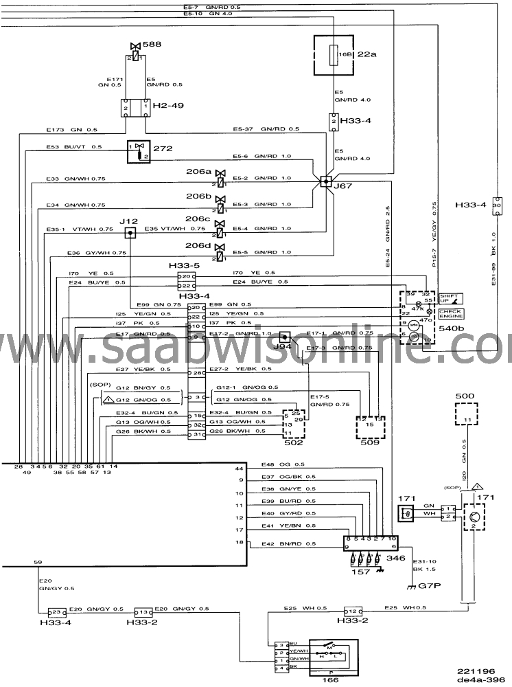
| List of components |
|
29
|
Brake light switch . On brake pedal.
|
|
102
|
Relay, fuel pump. In main relay holder under the
steering wheel, item I.
|
|
157
|
Spark plugs
|
|
166
|
Pressure switch for A/C system. Between front grille
and radiator.
|
|
171
|
Antifrost thermostat. On RH side of dashboard,
above the evaporator.
|
|
179
|
Boost pressure control valve In front of the air
cleaner.
|
|
202
|
Engine coolant temperature sensor. Between cyl. 3
and cyl. 4 intake manifolds.
|
|
203
|
Throttle position sensor. On the throttle
body.
|
|
206 a, b, c, d
|
Injector, cyl. 1, cyl. 2, cyl.3, cyl.4
|
|
229
|
Main relay, engine management system. In main
relay holder below the steering wheel, item L.
|
|
271
|
Heating element, heated oxygen sensor (integrated
in each oxygen sensor).
|
|
272
|
Idle air control (IAC) valve.
Adjacent to the throttle body.
|
|
321
|
EVAP canister purge valve (EVAP valve). By right-
hand MacPherson strut's upper mounting.
|
|
323
|
Fuel pump with integrated feed pump. In fuel
tank.
|
|
345
|
Crankshaft position sensor. In engine block at front
of engine.
|
|
346
|
Ignition discharge module
|
|
407
|
Intake air temperature sensor. In the intake
manifold.
|
|
431
|
Manifold absolute pressure sensor. On the stay
between the upper mounting points for the suspension struts.
|
|
444
|
Test socket, diagnostics PC (production
only)
|
|
445
|
Data link connector, ISAT scan tool. Under
dashboard adjacent to the steering wheel.
|
|
500
|
ICE control module. By the steering column, above
the relay holder.
|
|
508
|
Cruise Control. Beside the right-hand suspension
strut's upper mounting.
|
|
540 B
|
Main instrument. Display panel on the
dashboard.
|
|
547
|
ABS control module. Integrated in hydraulic
unit.
|
|
585
|
Pressure sensor, EVAP. On the fuel filler pipe, near
the tank.
|
|
588
|
Solenoid valve, EVAP shut-off. Beside the
evaporative emission canister.
|
|
589
|
Control module, Saab Trionic OBDII. Behind the
side trim on the right-hand side under the A pillar.
|
|
592Fa
|
Front heated oxygen sensor OBD II. In front section
of exhaust pipe.
|
|
592Ra
|
Rear heated oxygen sensor OBD II. In rear of
catalytic converter.
|
|
H 4-7
|
Under the rear seat adjacent to the fuel
pump.
|
|
H 16-1
|
Data link connector, 16 pin, CARB. Under
dashboard near the steering wheel
|
|
H 33-1
|
Grey 33-pin connector on a bracket below the left-
hand A pillar
|
|
H 33-2
|
Black 33-pin connector on bracket below left-hand A
pillar
|
|
H 33-4
|
On the bulkhead partition behind the glove
box
|
|
H 33-5
|
On the bulkhead partition behind the glove
box
|
|
J 2
|
About 130 mm from grounding point G33, towards
the ICE control module (instrument wiring harness).
|
|
J 4
|
About 450 mm from the rheostat, towards the main
instrument display panel (instrument wiring harness)
|
|
J 9
|
About 150 mm from the SID branch, towards
connector H33-4 (instrument wiring harness)
|
|
J 12
|
About 550 mm from connector H33-4 (engine
wiring harness, Trionic).
|
|
J 32
|
About 210 mm from the brake light switch, towards
the rheostat (instrument wiring harness)
|
|
J 32 (conv.)
|
About 150 mm from electrically heated rear window
branch, towards the luggage compartment
|
|
J 49
|
About 180 mm from the ICE control module branch,
towards the rheostat (instrument wiring harness)
|
|
J 56
|
About 290 mm from the rheostat, towards the brake
light switch (instrument wiring harness)
|
|
J 67
|
About 180 mm from injector No. 1, towards the
Trionic control module (engine wiring harness, Trionic)
|
|
J 68
|
About 45 mm from the cable tie on the Trionic control module
connector (engine wiring harness, Trionic)
|
|
J 93
|
In ICE control module branch (instrument wiring
harness)
|
|
J 94
|
About 140 mm from connector H33-4, towards the
centre console (instrument wiring harness)
|
|
J 96
|
About 110 mm from the ICE control module branch,
towards the brake light switch (instrument wiring harness)
|
|
J 150
|
About 80 mm from the G3 grounding point branch,
towards the cabin.
|
|
J150 (conv.)
|
About 50 mm from the G3 grounding point branch,
towards the cabin.
|
|
J 157
|
About 100 mm from the rheostat branch, towards
the SID
|
|
J 160
|
About 95 mm from the cable tie on the Trionic OBD
II control module connector
|
|
J 161
|
About 10 mm from the connector H33-4 branching
point, towards the rubber grommet in the bulkhead partition.
|
|
G3
|
Grounding point. In the luggage compartment under
the LH rear light.
|
|
G 5
|
Grounding point. Under rear seat on left-hand
side.
|
|
G 7 P
|
Grounding point, power ground. Bracket on rear of
engine.
|
|
G7 S
|
Grounding point, signal ground. Bracket on rear of
engine.
|
|
22 A
|
Main fuse box in end of dashboard, on
driver's side.
|
|
MAXI
|
Maxi fuse 2. In maxi fuse holder in engine bay, behind the
battery.
|
This project is supported by memberships and donations. If you use this site, please consider Joining SCNA and/or making a donation.
Our Friends
