Checking the pedal switch and selectorlever position sensor (automatic transmission)
|
|
Checking the pedal switch and selector
lever position sensor (automatic transmission)
|
|
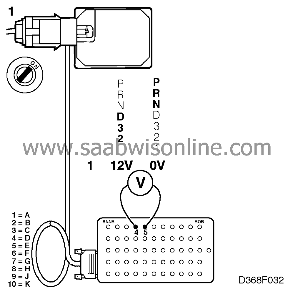
1.
|
Connect the BOB and check
that about 12 V is present across pin D (4) of the Cruise Control connector and a good ground
(selector lever in position D, 1, 2 or 3).
There should be zero voltage (0 V) when the selector lever is in position P, R or N.
|
|
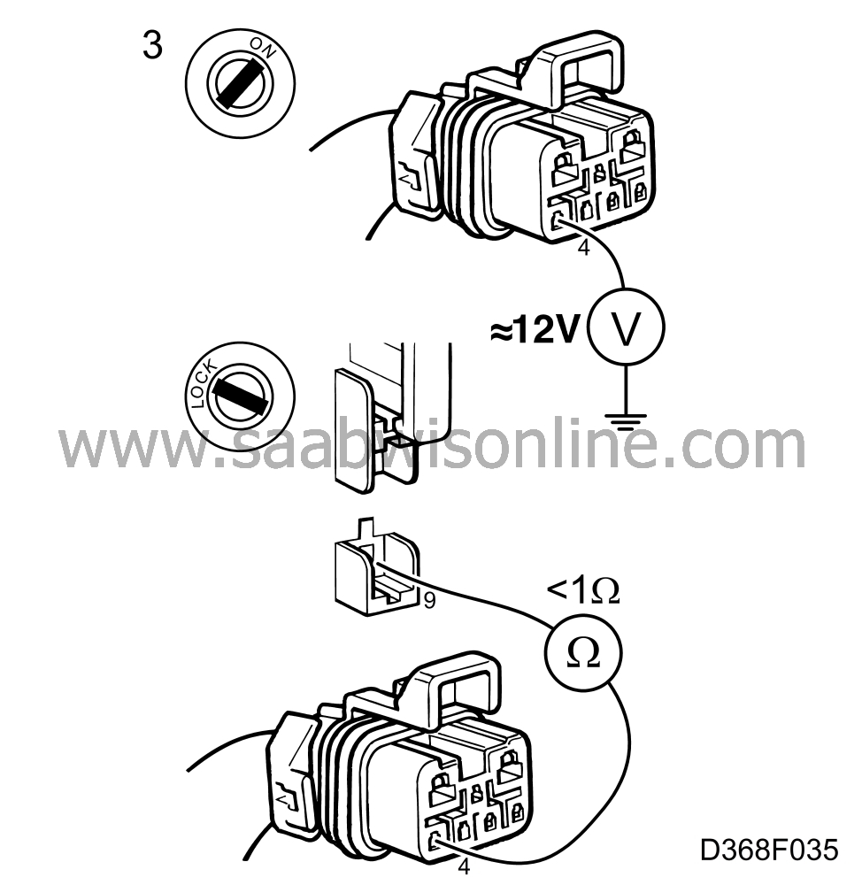
3.
|
If the voltage is not OK, check that about 12 V is present on pin 4 of the
selector lever's 7-pin connector.

If the voltage is OK, continue with point 4.
If the voltage is not OK, measure the resistance across the load side of the
fuse and pin 4 of the selector lever's 7-pin connector.
If the resistance is > 1 ohm, check the wiring and rectify the fault.
|
|
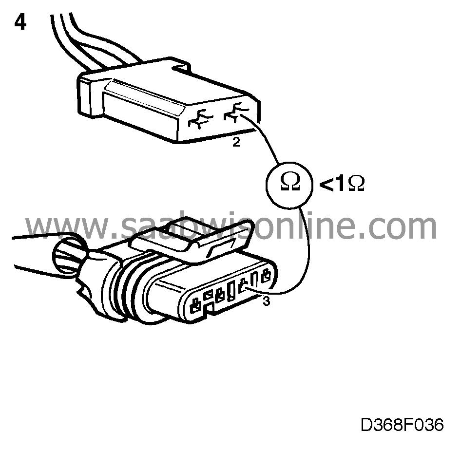
4.
|
Check the wiring for continuity or a short circuit by measuring the
resistance across pin 3 of the selector lever's 4-pin connector and pin 2 of the brake
pedal switch connector.

If the resistance is > 1 ohm, the fault is in the selector lever.
Check or adjust the selector lever as described in Service Manual 4:2 "Automatic
transmission".
If the resistance is > 1 ohm, check the wiring and rectify the fault.
|
|
5.
|
Measure the resistance across pins 1 and 2 of the brake pedal switch
when the brake pedal is depressed and also when it is not depressed.

If the resistance with the pedal in the normal position (not depressed) is > 1
ohm, adjust the pedal switch or perhaps fit a new one.
Depressing the pedal breaks the circuit. If resistance can be measured in the
circuit, fit a new pedal switch.
|
|
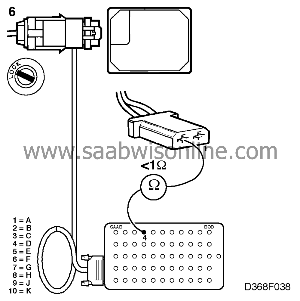
6.
|
If the pedal switch is OK, check the wiring for continuity or a short circuit
by measuring the resistance across pin 1 of the brake pedal connector and pin D (4) of the
Cruise Control connector.

The resistance should be > 1 ohm.
|


