Wiring diagram, Main instrument display panel 1 M1996 (I)
| Wiring diagram, Main instrument display panel 1 M1996 (I) |
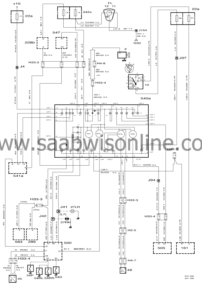
| List of components |
|
2
|
Generator, at rear of engine on RH
side.
|
|
10
|
Lights stalk switch on left (LHD) or right (RHD) side
of steering wheel.
|
|
11
|
Main beam lamp.
|
|
12
|
Dipped beam lamp.
|
|
16
|
Rheostat, to left (LHD) or right (RHD) of steering
wheel.
|
|
22a
|
Main fuse box, behind the access flap in the glove
box.
|
|
27
|
Direction indicator lamps, LH, in front and rear light
clusters.
|
|
28
|
Direction indicator lamps, RH, in front and rear light
clusters.
|
|
42
|
Brake fluid warning lamp switch on brake fluid
reservoir.
|
|
43
|
Handbrake switch under the centre console by the
handbrake lever.
|
|
44
|
Oil pressure sensor on the sump.
|
|
45
|
Coolant temperature sensor on LH side of
engine.
|
|
46
|
Fuel level sensor in fuel tank.
|
|
54
|
Door switch in door openings.
|
|
161
|
Rear fog light switch to left (LHD) or right (RHD) of
steering wheel.
|
|
228b
|
Front filament monitor in main fuse box in engine
bay.
|
|
289
|
Anti-theft alarm control module under LH front seat.
|
|
331
|
Airbag control module under centre console behind
the handbrake lever.
|
|
342a
|
Main fuse box in the engine bay.
|
|
416
|
EXH relay in main fuse box in dashboard.
|
|
500
|
ICE control module on top of relay holder adjacent
to steering column.
|
|
502
|
TCM control module on bulkhead partition behind
the glove box.
|
|
505
|
M2.10.3 control module on RH side behind the side
trim below the A pillar.
|
|
508
|
Cruise Control system control module in engine bay
on RH side below the windscreen.
|
|
540a
|
Main instrument display panel 1
|
|
541a
|
SID unit in centre of dashboard.
|
|
547
|
ABS control module integrated in brake unit in
engine bay.
|
|
583
|
Anti-theft alarm with VSS under LH front seat.
|
|
H2-5
|
Under the cover under the rear seat.
|
|
H4-7
|
Adjacent to the fuel pump under the rear seat.
|
|
H4-8
|
Brown connector on LH side of engine below the
cable conduit.
|
|
H33-2
|
Black 33-pin connector on bracket below left-hand A
pillar.
|
|
H33-3
|
Grey-blue 33-pin connector on bracket below left-
hand A pillar.
|
|
H33-4
|
On bulkhead partition behind the glove
box.
|
|
|
|
|
G30
|
Grounding point, LH structural member behind the
battery.
|
|
G33S
|
Grounding point, connector bracket (Signal) below
left-hand A pillar.
|
|
G33P
|
Grounding point, connector bracket (Power) below
left-hand A pillar.
|
|
G34P
|
Grounding point, control module bracket (Power) below right-
hand A pillar.
|
This project is supported by memberships and donations. If you use this site, please consider Joining SCNA and/or making a donation.
Our Friends
