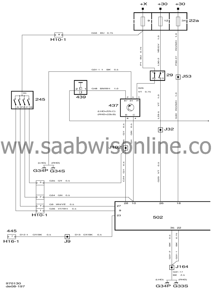
Wiring diagram TCM OBD II (I)
| Wiring diagram TCM OBD II (I) |
|
16
|
Rheostat, instrument lighting
|
|
22A
|
Main fuse board, dashboard
|
|
29
|
Brake light switch
|
|
91
|
Lamp, selector lever position indicator lighting.
|
|
245
|
Selector lever position sensor on the front of the gearcase.
|
|
430
|
Control module, Saab Trionic, on right-hand side behind the side trim, below the A pillar.
|
|
437
|
Relay, SHIFT LOCK, main fuse box, dashboard (plac. 22B:C (LHD) and plac. 22B:B (RHD)).
|
|
439
|
Solenoid, SHIFT LOCK, under selector lever.
|
|
445(H16-1)
|
Data link connector, 16-pin, CARB adjacent to the steering wheel under the dashboard.
|
|
502
|
TCM control module on bulkhead partition behind the glove box.
|
|
506
|
Switch, WINTER, on the centre console beside the selector lever.
|
|
507
|
TCS control module, V6, under the right-hand front seat.
|
|
531
|
Solenoid valves, transmission control module, in valve housing under the transmission.
|
|
532
|
Input shaft speed sensor, on the transmission.
|
|
533
|
Output shaft speed sensor, on the transmission.
|
|
534
|
Kickdown switch; under accelerator pedal
|
|
535
|
Temperature sensor, transmission fluid, under the transmission.
|
|
537
|
SPORT switch on the selector lever knob.
|
|
540a
|
Main instrument display panel, low specification
|
|
540b
|
Main instrument display panel, high specification
|
|
586
|
Control module, Motronic 4.1, on right-hand side behind the side trim below the A pillar.
|
|
587
|
Control module, Motronic 5.2, on right-hand side behind the side trim below the A pillar.
|
|
589
|
Control module, Saab Trionic OBD II, on right-hand side behind the side trim below the A pillar.
|
|
|
4-pin connectors
|
|
H4-13 (LHD)
|
About 220 mm from the rheostat (instrument wiring).
|
|
H4-13 (RHD)
|
In the branch leading to the climate control panel (instrument wiring).
|
|
H4-15 (LHD)
|
About 250 mm from the SID branch leading to the right-hand loudspeaker (instrument wiring).
|
|
|
6-pin connector
|
|
H6-5(LHD)
|
About 220 mm from the rheostat (instrument wiring).
|
|
H6-5(RHD)
|
In the branch leading to the climate control panel (instrument wiring).
|
|
|
10-pin connectors
|
|
H10-1
|
On bracket behind battery
|
|
|
16-pin connector
|
|
H16-3
|
On bracket behind battery
|
|
|
33-pin connectors
|
|
H33-4
|
On the bulkhead partition behind the glove box.
|
|
|
Crimps
|
|
J4 (LHD)
|
About 450 mm from the rheostat towards the main instrument display panel (instrument wiring harness).
|
|
J4 (RHD)
|
About 240 mm from the rheostat towards the main instrument display panel (instrument wiring harness).
|
|
J9 (LHD)
|
About 150 mm from the SID branch towards connector H33-4 (instrument wiring).
|
|
J9 (RHD)
|
About 50 mm from the radio branch towards the SID (instrument wiring).
|
|
J32 (LHD)
|
About 210 mm from the brake light switch towards the rheostat (instrument wiring).
|
|
J32 (RHD)
|
About 60 mm from the rheostat branch towards the ICE control module (instrument wiring).
|
|
J53 (LHD)
|
About 480 mm from the main instrument display panel branch towards the SID (instrument wiring).
|
|
J53 (RHD)
|
About 150 mm from the main instrument display panel branch towards ICE (instrument wiring).
|
|
J85 (LHD)
|
About 270 mm from connector H33-4 (instrument wiring).
|
|
J85 (RHD)
|
In the automatic transmission selector lever branch (instrument wiring).
|
|
J94 (LHD)
|
About 140 mm from connector H33-4 towards the centre console (instrument wiring harness).
|
|
J94 (RHD)
|
About 40 mm from the connector bracket branching point towards grounding point G34 (instrument wiring harness).
|
|
J95 (LHD)
|
About 340 mm from grounding point G34 towards the centre console (instrument wiring).
|
|
J95 (RHD)
|
About 90 mm from the connector bracket branch towards grounding point G34 (instrument wiring).
|
|
J102 (LHD)
|
About 320 mm from the brake light switch towards the rheostat (instrument wiring).
|
|
J102 (RHD)
|
About 160 mm from the brake light switch (instrument wiring).
|
|
J164 (LHD)
|
About 290 mm from grounding point G34 towards the centre console (instrument wiring).
|
|
J164 (RHD)
|
About 300 mm from the transmission control module (instrument wiring).
|
|
J168 (LHD)
|
About 80 mm from the MAXI fuse box branch towards the reversing light switich (instrument wiring).
|
|
J168 (RHD)
|
About 380 mm from the MAXI fuse box (instrument wiring).
|
|
|
Grounding points
|
|
G4
|
Grounding point, centre console between the front seats.
|
|
G33S
|
Grounding point, connector bracket (Signal) below the left-hand A pillar.
|
|
G34P
|
Grounding point, control module bracket (Power) below right A-pillar
|
|
G34S
|
Grounding point, control module bracket (Signal) below right A-pillar
|
This project is supported by memberships and donations. If you use this site, please consider Joining SCNA and/or making a donation.
Our Friends
