Servo pump
| Servo pump |
The pump incorporates a control valve for regulation of the pressure and flow and also an overflow valve.
|
||||||||||||||||
| Principle of operation |
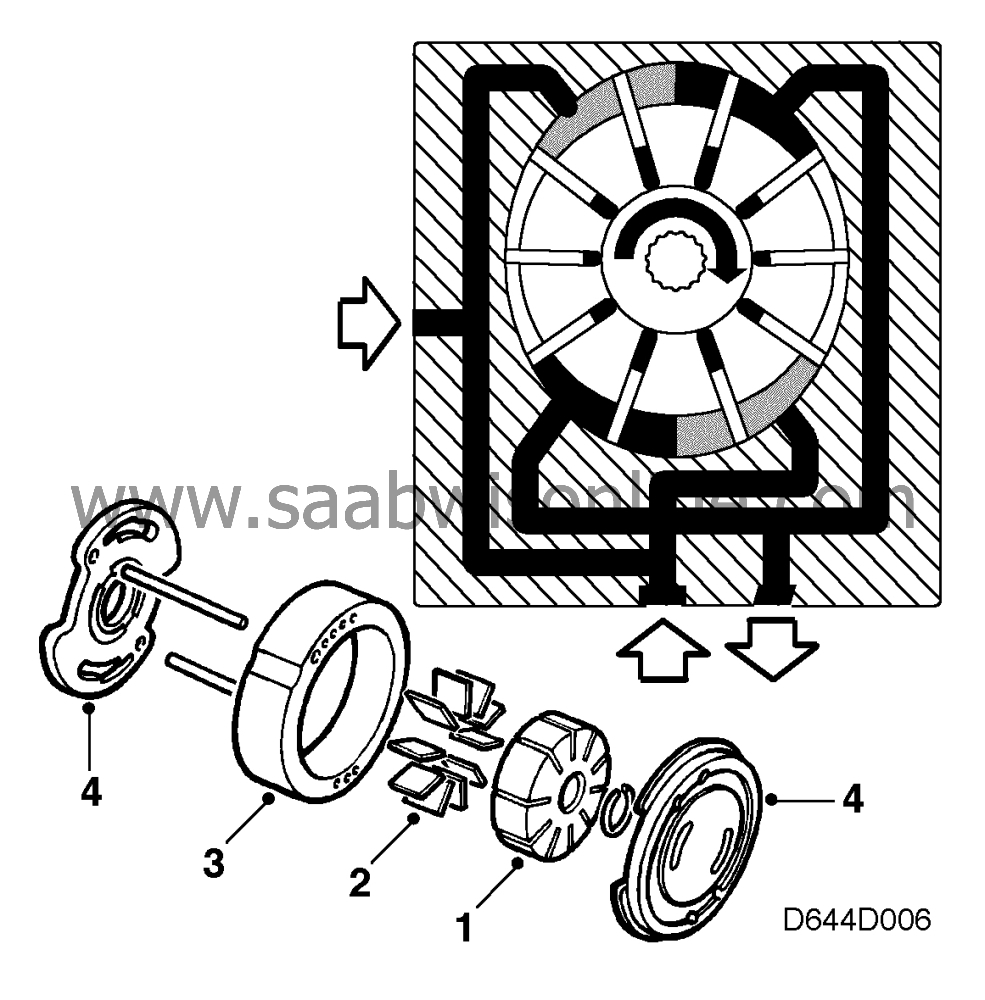
The pump consists of a rotor (1) containing a number of slots, a vane (2) for each slot, a pump casing (3), and two end plates (4) with inlet and outlet ports for the hydraulic fluid.
Due to the oval shape of the pump casing, the volume between the vanes increases and decreases twice during each revolution of the rotor. Inlet ports lead to the areas in which the volume increases and outlet ports from those in which the volume decreases, thereby producing a pumping effect. Apart from being forced out by centrifugal force, the vanes are also pressed outwards against the pump casing by the pressure of the fluid flowing through the slots at the bottom of the vanes.
| Control of pressure and flow |
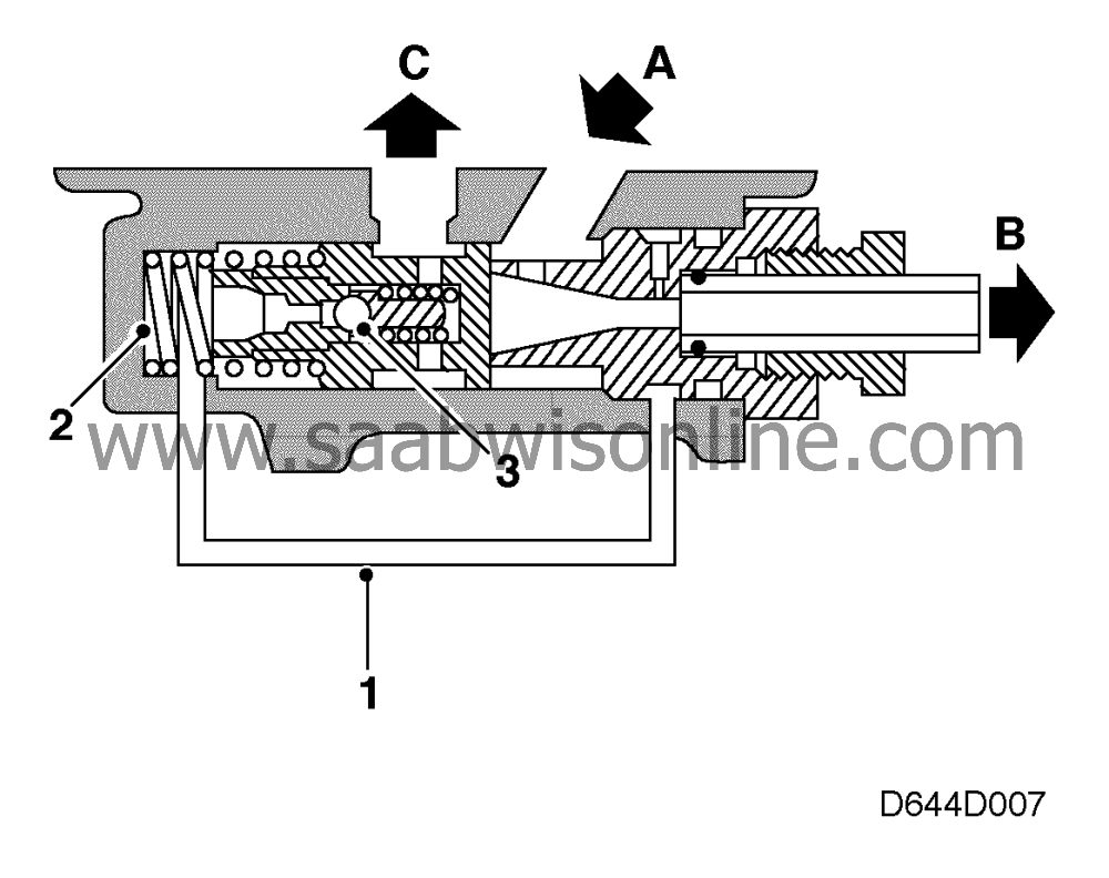
1 Connecting line
2 Spring
3 Overflow valve
| A. |
From the pump's deliveyr
side
|
|
| B. |
To the steering gear
|
|
| C. |
To the pump's suction side
|
|
The function of the control valve is to regulate the flow from the pump so that it remains constant, regardless of engine/pump rpm.
One side of the control valve is in direct communication with the delivery side of the pump (A). The pump outlet (B) incorporates a restriction from which a connecting passage (1) leads to the other side of the valve, which is fitted with a spring (2). In the rest position, the valve is pressed against the outlet side.
Inside the control valve is an overflow valve (3) which, when the pressure exceeds a certain limit, is actuated by the pressure on the spring-loaded side of the control valve.
For the control valve to be capable of working, a certain amount of hydraulic fluid circulates continuously through valves (A) and (C), although not when the steering wheel is turned to an end stop. The pump delivers a maximum pressure of about 90 bar and a maximum flow rate of about 6.0 litres per minute.
| Regulation at low rpm |
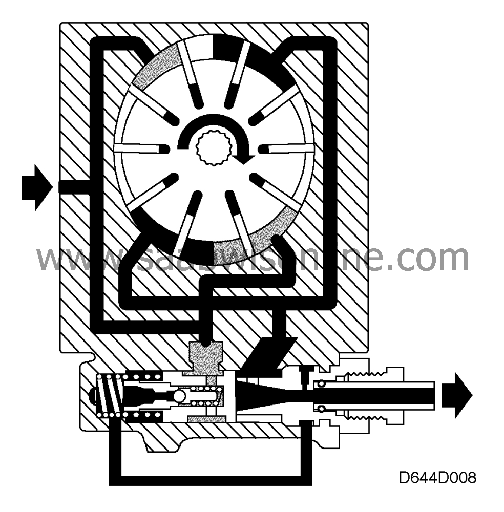
The pressure raised by the pump (shaded portion) is reduced slightly by the restriction in the pump outlet.
The reduced pressure is also communicated to the spring- loaded side of the control valve, giving rise to a slight pressure difference between the two sides of the valve. Owing to the low speed of the pump, however, the difference in pressure is insufficient to overcome the force of the spring and actuate the valve.
| Regulation at high rpm (pump in flow control mode) |
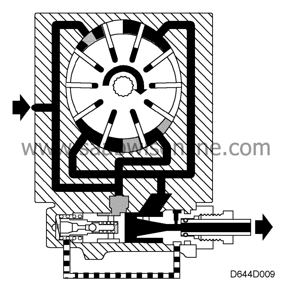
The flow of hydraulic fluid inside the pump increases with increasing engine rpm. Due to the constriction at the pump's outlet, the flow rate of the fluid increases. This brings about a reduction of the pressure in the connecting line, which means that the pressure on the spring side of the control valve will be lower than the pressure on the outlet side of the control valve. This causes the control valve to compress the spring, thus opening a passage to the suction side of the pump to allow a certain degree of recirculation so that a constant flow from the pump is obtained, regardless of engine/pump speed.
| Steering wheel turned to full lock |
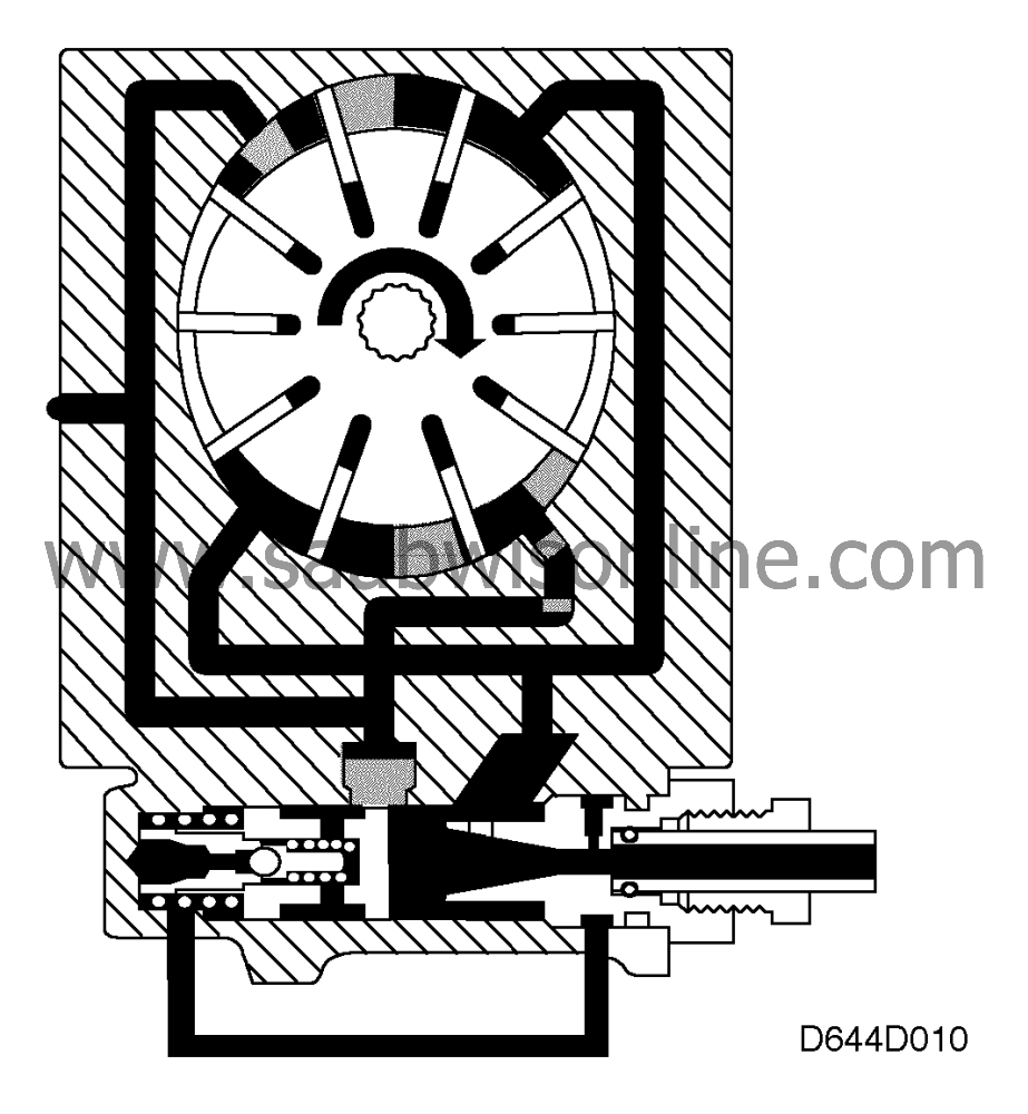
Pump speed in this case is often low. When the steering wheel is turned to full lock the control valve of the steering gear closes. The flow of fluid from the pump will then be zero.
The high pressure thus arising is directed via the connecting passage to the spring-loaded side of the control valve. The pressure opens the overflow valve and allows the fluid to pass to the inlet side of the pump. The pressure difference across the control valve forces it to move towards the spring and so open the port for recirculation of the full delivery flow from the pump.
The predetermined maximum pressure is maintained as long as the control valve remains closed.

 Warning

