Air conditioning system
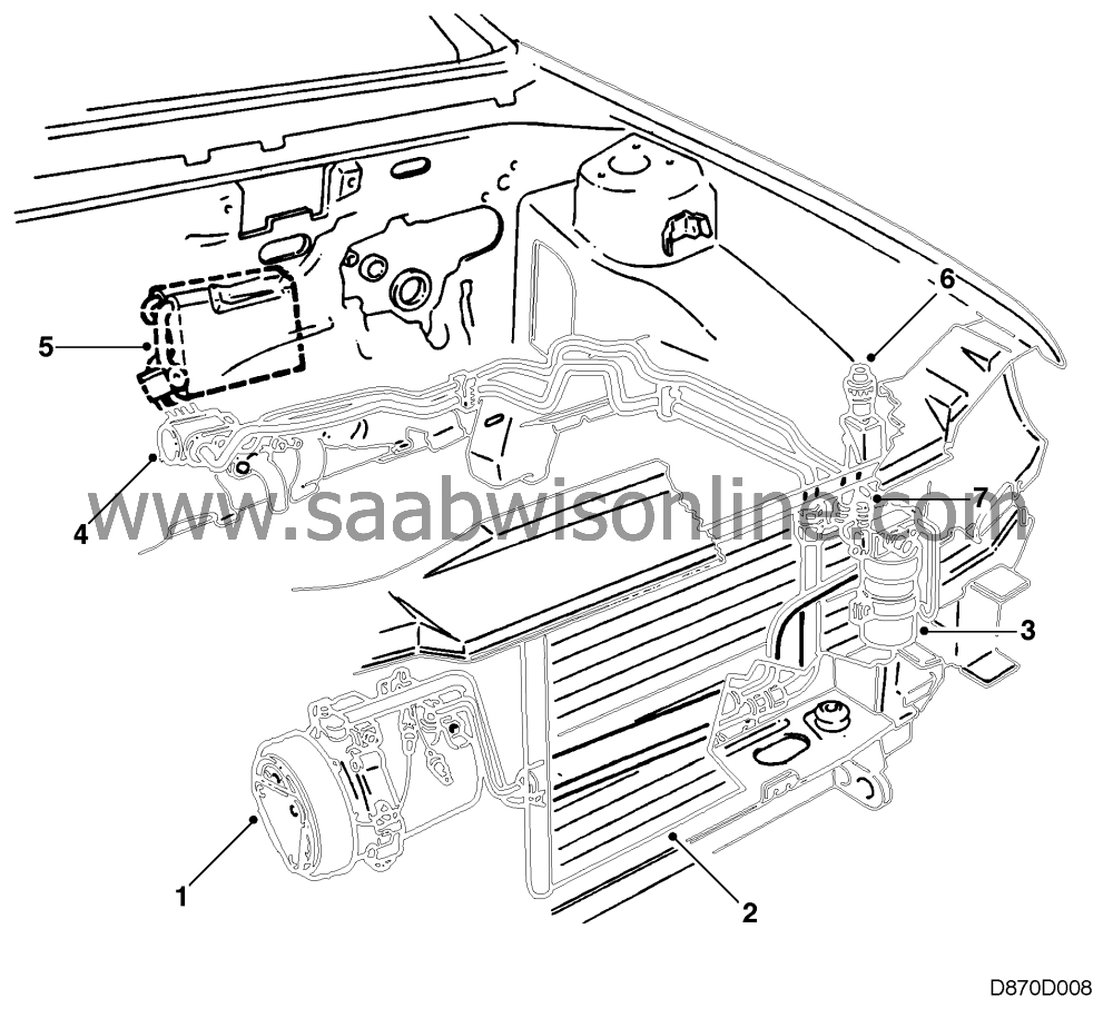
| Air conditioning system |
| 1. |
Compressor
|
|
| 2. |
Condenser
|
|
| 3. |
Receiver
|
|
| 4. |
Expansion valve (fitted in the climate control unit on certain variants)
|
|
| 5. |
Evaporator
|
|
| 6. |
Service connection, low-pressure side
|
|
| 7. |
Service connection, high-pressure side
|
|
The task of the air conditioning system is to lower the temperature of the cabin to a comfortable level when the outside temperature is high. When the weather is damp, it can also keep the windows free from misting with a low fan speed.
The AC unit does not produce cold air but leads off heat from the interior. To do this we use a substance or an agent which is cooler than the air, as air always flows from a hot object to a cooler one.
The refrigerant used for air conditioning in the Saab 900 is a fluid, R134a, which is boiled and then evaporated at low temperatures (-30 ° C at normal air pressure). The refrigerant has a constant relationship between pressure and temperature, which means that if the pressure changes, the temperature also changes and vice versa. The relationship applies on condition that the volume is constant.
This relationship is used by the AC system. By allowing the refrigerant to circulate in a closed system and changing its pressure you can also make it change temperature. If the pressure, and thereby the temperature, changes sufficiently, the refrigerant starts to evaporate (boil). At the prevailing pressure on the low-pressure side in the system the refrigerant evaporates at about 0 - +4 ° C. The process occurs in the AC system evaporator.
One condition for evaporation of the refrigerant is that there is heat available. This heat is taken from the air around the evaporator. When the heat is absorbed by the refrigerant in the evaporator, it cools the ambient air. This is the cool air that flows into the cabin.
The heat that is absorbed by the refrigerant in the evaporator is transported to the engine bay, where it is passed to the atmosphere by an air-cooled condenser.

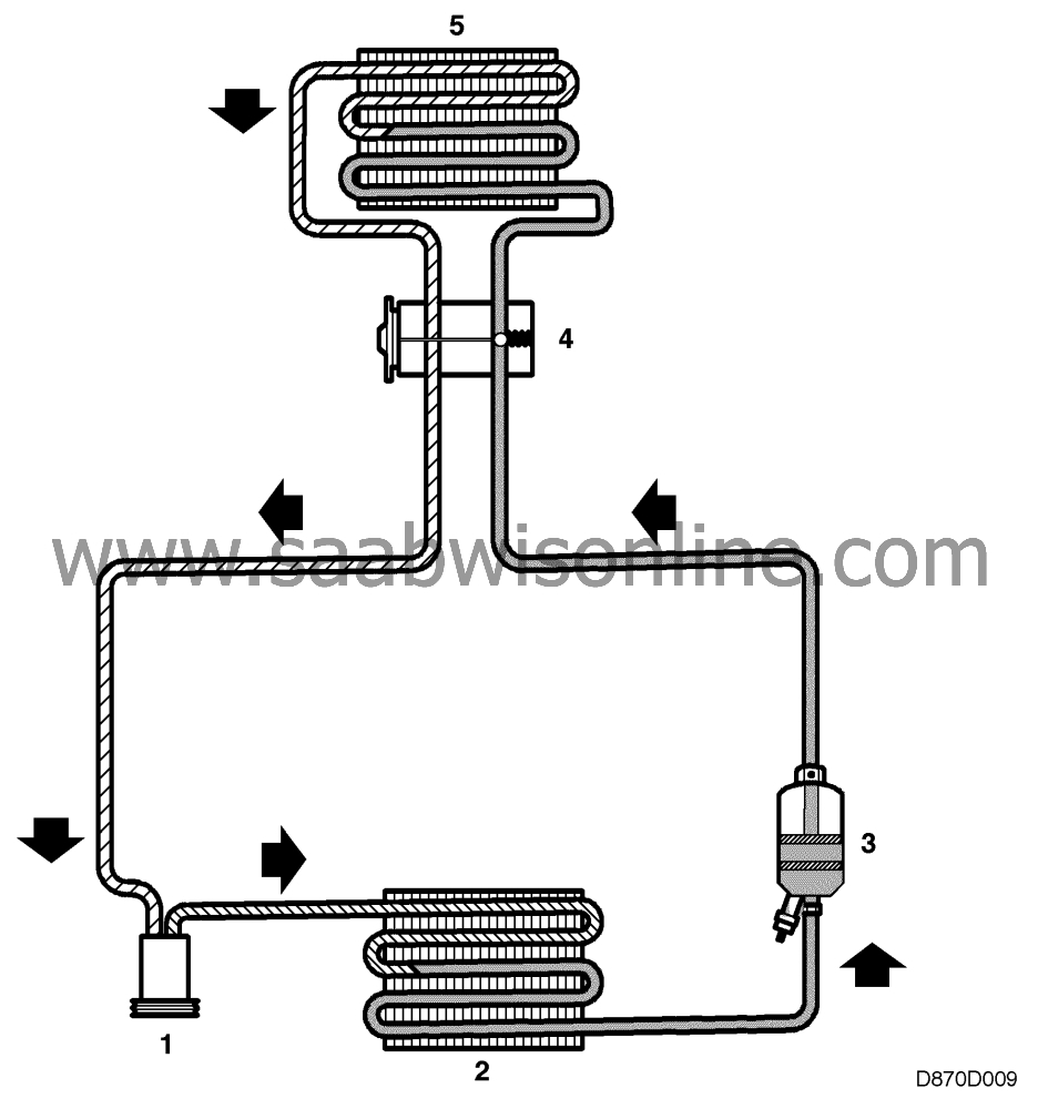
AC system, outline diagram
= gas, high pressure
= liquid, high pressure
= liquid, low pressure
= gas, low pressure
| Mode of operation |
1 Compressor
The refrigerant arrives at the compressor from the evaporator at low pressure and as a gas. It is compressed in the compressor, which increases its pressure and temperature. The warm, gaseous refrigerant is then forced into the condenser.2 Condenser
The hot, high-pressure refrigerant is pumped by the compressor into the condenser's coiled tubes. The coiled tubes are fitted with cooling flanges around which air is circulated by the ventilation fan and the airstream. As heat is always transferred from a warmer to a cooler object, the hot refrigerant will transfer some of its heat to the cooler air. The hot, gaseous refrigerant will then lose some of its heat, start to condense and thus become a liquid.3 Receiver
The refrigerant is stored and dehumidified in the receiver. The refrigerant enters the receiver as a liquid under high pressure and at high temperature. It passes through the filter, where it is dehumidified and any particles removed. The refrigerant is then transported, as a liquid, to the expansion valve. The system's pressure monitor is located on the receiver (two pressure monitors are used in hot-climate countries).4 Expansion valve
The refrigerant which enters the expansion valve is in liquid form under high pressure and at high temperature. The task of the expansion valve is to adjust the amount of refrigerant which is sprayed into the evaporator. The valve does not allow in more refrigerant than can be evaporated at any one time.5 Evaporator
After the expansion valve, the refrigerant enters the evaporator where it expands. The pressure in the evaporator is considerably lower due to the suction action in the compressor. When the refrigerant expands, it becomes a gas (evaporates). Heat must be added to make this happen. This heat is taken from the air around the evaporator. The cooled air is then sent to the interior of the car. The refrigerant then goes to the compressor in the form of a gas.| AC system power supply |
+ 54 voltage is fed via fuse 3 to the ventilation fan switch. If the switch is in one of the positions 1 to 4 and the A/C button is ON, the voltage is fed on to the ICE. ICE checks the engine temperature and if it is lower than + 126 ° C, the voltage is fed to the anti-frost thermostat. If the temperature in the evaporator is approx. +5 ° C or higher, the voltage is fed to the engine management system.
The engine management system increases the idling speed and grounds the cable to the three stage pressure switch. If the pressure in the AC system is higher than 2 bar but lower than 30 bar, the pressure switch grounds the cable to the AC relay. From fuse 5 in the fuse holder 342A, current is fed via the AC relay to the thermal fuse in the compressor overheating protection. If the temperature in the compressor is lower than + 140 ° C, the current is fed to the solenoid clutch in the compressor.


