Power supply and grounding
| Power supply and grounding |
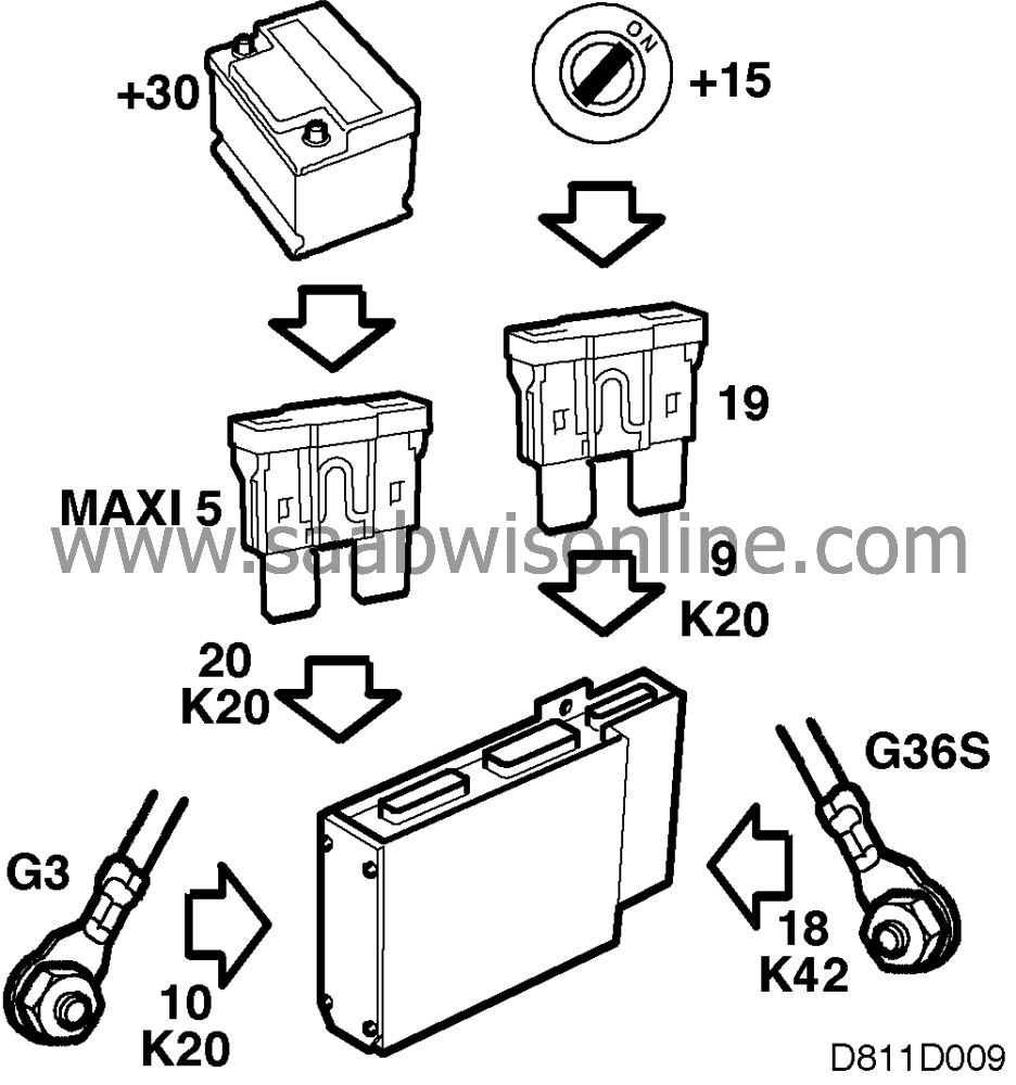
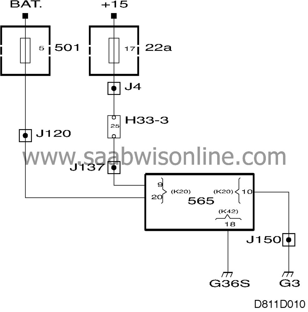
The control module is supplied with +30 via maxi fuse no. 5 on pin 20 (K20) and with +15 via fuse no. 19 on pin 9 (K20).
The control module is grounded as follows:
| • |
Power ground on pin 10 (K20). Grounds the motors.
|
|
| • |
Signal ground on pin 18 (K42). Grounds the control module processor and potentiometers.
|
|
| • |
Chassis ground. The control module casing must be connected to the chassis to minimize the risk of it interfering with other systems.
|
|
This project is supported by memberships and donations. If you use this site, please consider Joining SCNA and/or making a donation.
Our Friends
