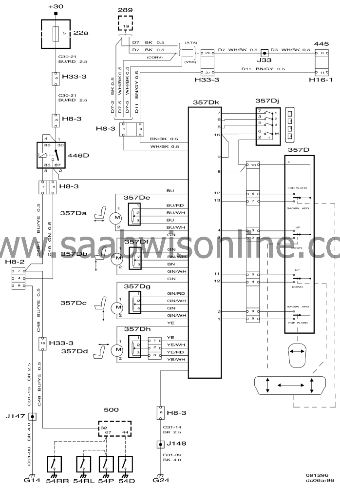
Wiring diagram, electrically adjustable seats with memory RHD
| Wiring diagram, electrically adjustable seats with memory RHD |
List of components
| No. | Description |
|
Components
|
|
|
22A
|
Fuse holder in the dashboard
|
|
54
|
Door switches in each door pillar
|
|
357A-D
|
Electric motors, left-hand, under the seat
|
|
357E-H
|
Position sensors, electrically adjustable seat with memory, under the seat on each motor shaft
|
|
357J
|
Switch, memory, on outside of seat
|
|
357K
|
Control module, electrically adjustable seat with memory
|
|
357
|
Switch, electrically adjustable seat, left-hand
|
|
445
|
Diagnostic socket (16-pin), under the dashboard on the driver's side
|
|
446
|
Relay, electrically adjustable driver's seat
|
|
500
|
ICE control module, beside the steering column above the relay holder
|
|
8-pin connectors
|
|
|
H8-3
|
Under the driver's seat
|
|
H8-2
|
Under the front passenger's seat
|
|
33-pin connectors
|
|
|
H33-1
|
Blue 33-pin connector, on bracket below left-hand A pillar
|
|
H33-3
|
Grey 33-pin connector on bracket below left-hand A pillar
|
|
Crimps
|
|
|
J49
|
|
|
J56
|
|
|
J60
|
|
|
Grounding points
|
|
|
G14
|
Grounding point, left-hand seat member, under left-hand front seat
|
|
G24
|
Grounding point, right-hand seat member, under right-hand front seat
|
|
G33S
|
Grounding point, connector bracket (Signal), below left-hand A pillar on connector bracket
|
|
G33P
|
Grounding point, connector bracket (Power), below left-hand A pillar on connector bracket
|
This project is supported by memberships and donations. If you use this site, please consider Joining SCNA and/or making a donation.
Our Friends
