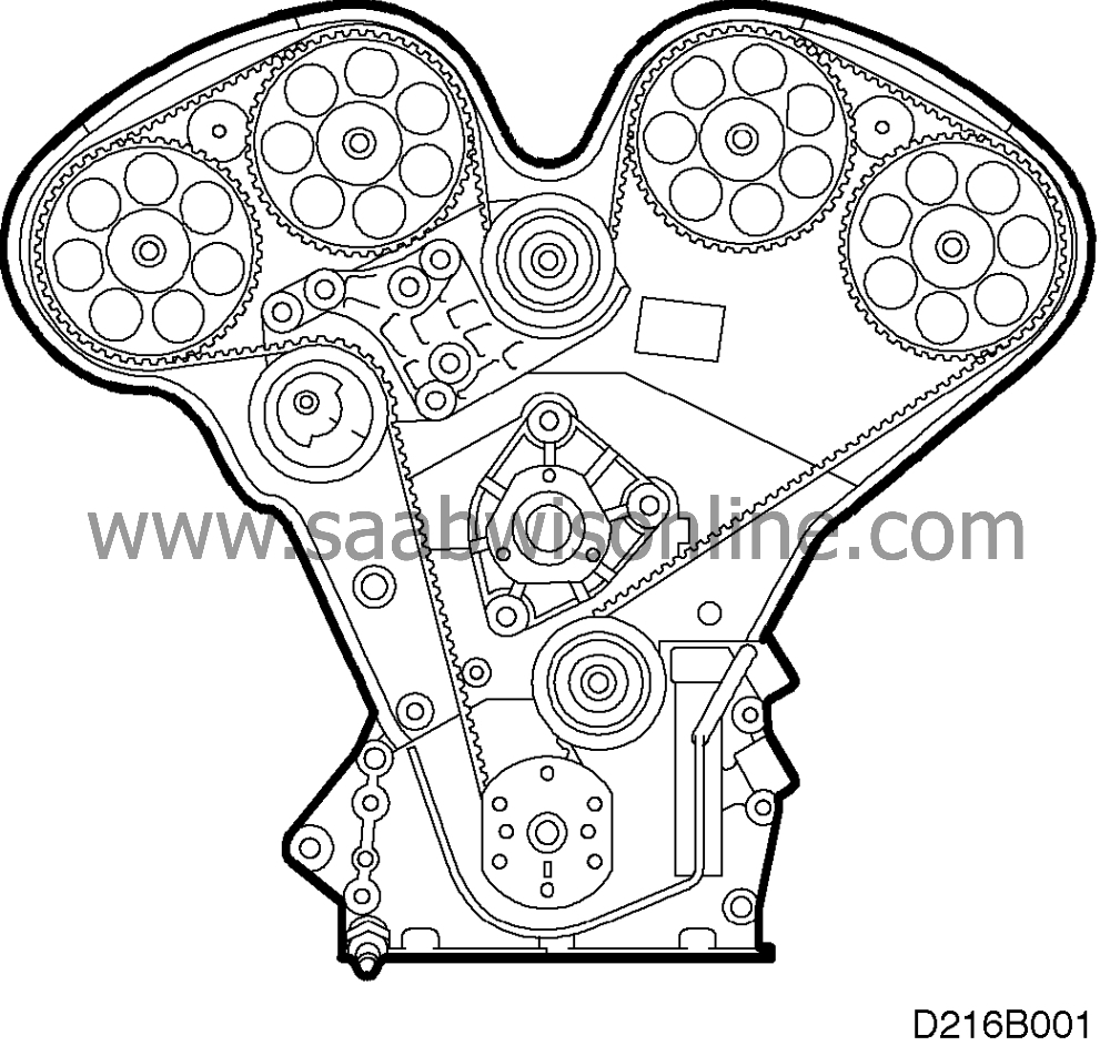
Fitting new camshaft timing belt andtiming covers
|
MODIFICATION INSTRUCTION
|
|
Bulletin Nbr:
|
215-1726
|
|
Date:
...........
|
MARCH 1997
|
|
Market:
|
ACCORDING TO LIST
|
|
|
Fitting new camshaft timing belt and
timing covers
|
|
Customer satisfaction campaign 10444
|
As regards cars in stock, the work shall be done before cars are
delivered.
Owners of cars that have already been delivered should be informed of the modification
in person and asked to get in touch with their nearest Saab dealer to have the work carried
out as soon as possible.
All V6-engine cars in the following chassis-No. range:
V2000001-V2007396 (3-D/5-D)
V7000001-V7001213 (Convertible)
A new longer-life camshaft timing belt and belt tensioner have been introduced
to reduce service frequency.
Camshaft timing belt: 47 70 491
Belt tensioner: 47 70 509
Timing cover, outer: 47 70 517
Timing cover, inner: 47 70 525
Before starting work, check box B2 in the campaign plate. If there is no mark in
the box, proceed as follows.
|
1.
|
Place a container under the radiator, open the
drain plug and drain the coolant. Removing the cap on the expansion tank will help the coolant
to drain faster.
|
|
2.
|
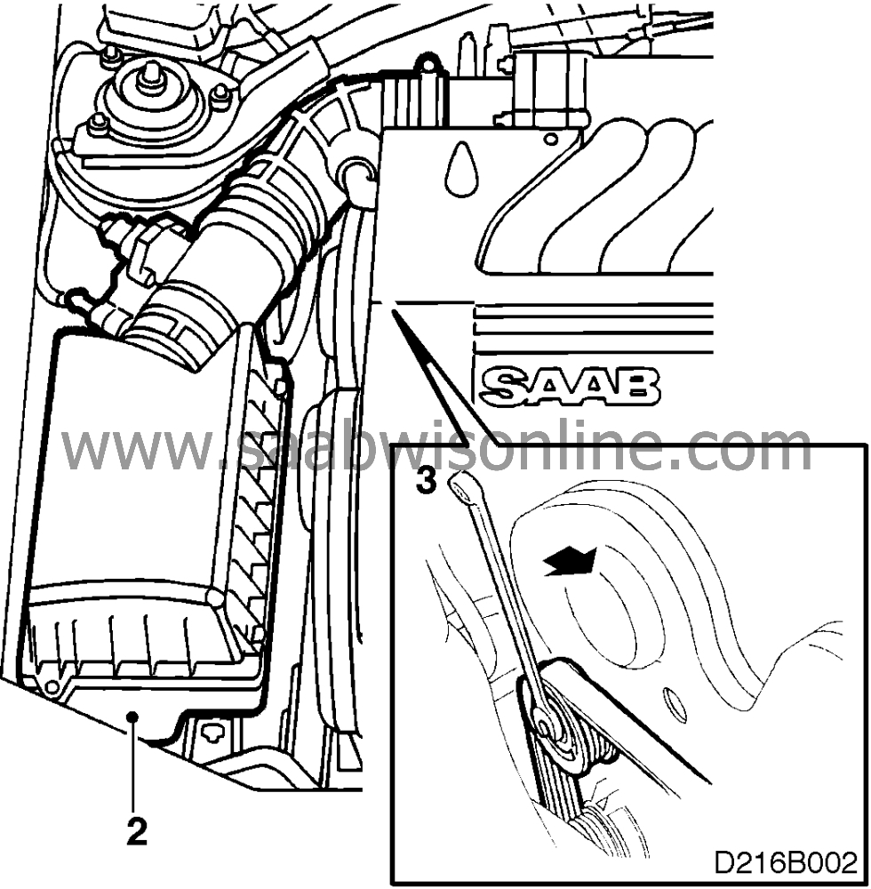
Remove the air cleaner complete with hoses.
|
|
3.
|
Slacken the pulley bolts. Using a 15-mm socket, turn the belt tensioner bolts
towards the front of the car to slacken the tension in the belt. Ease the belt off the water-pump
pulley and gently release the belt tensioner.
|
|
4.
|
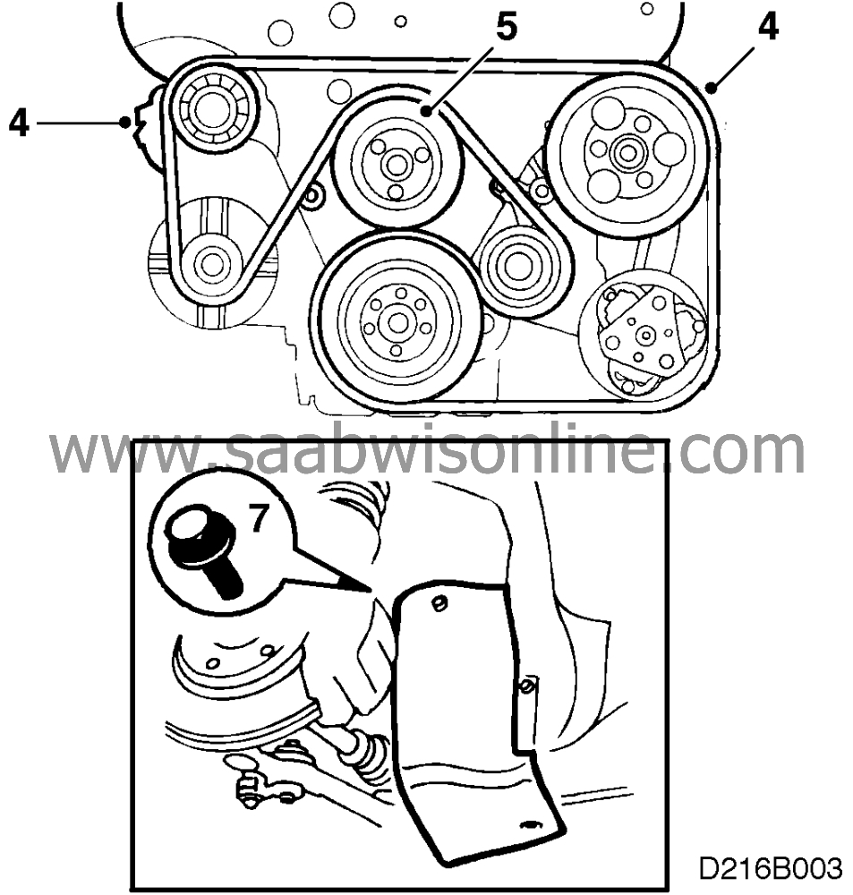
Remove the belt tensioner, and the pulley for the steering servo
pump.
|
|
5.
|
Remove the water-pump pulley (lever the engine towards the LH side of the car,
using the engine-mounting bracket for purchase).
|
|
6.
|
Remove the outer timing cover.
|
|
7.
|
Raise the car, remove the RH front wheel and the wheel-arch liner. Remove the
crankshaft pulley (six bolts--
the centre bolt).
|
|
8.
|
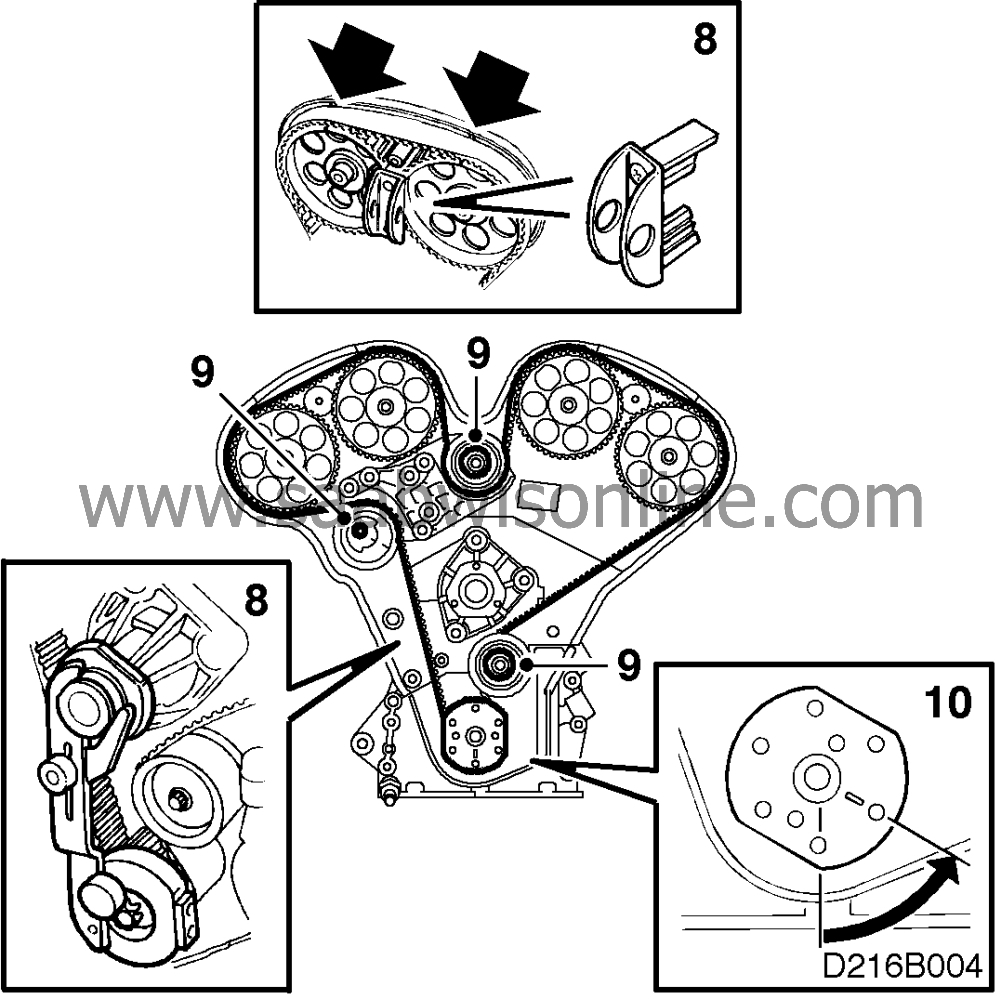
Using tool KM-800-20, line up the timing marks on the camshaft pinions and the
timing cover and do the same for the crankshaft. Immobilize the camshaft pinions using tools
KM-800-1 and KM-800-2, and the crankshaft using tool KM-800-10.
|
|
9.
|
Slacken and remove the timing belt. Slacken the bolts in the idler
wheels.
|
|
10.
|
Rotate the crankshaft to 60° BTDC.
|
|
11.
|
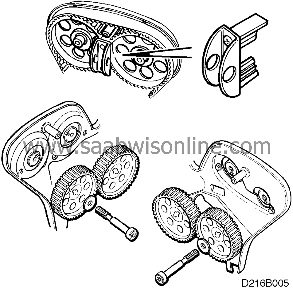
Slacken the camshaft pinion bolts and remove the tools followed by the
pinions.
|
|
12.
|
Undo the bolts and lift off the belt tensioner.

|
|
13.
|
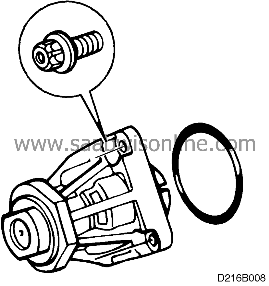
Remove the water pump, taking care not to damage the ’O’
ring.
|
Important
|
|
Always leave a tray under the engine when working on the cooling system, as a fair
amount of coolant is left in the engine after draining.
|
|
|
|
|
14.
|
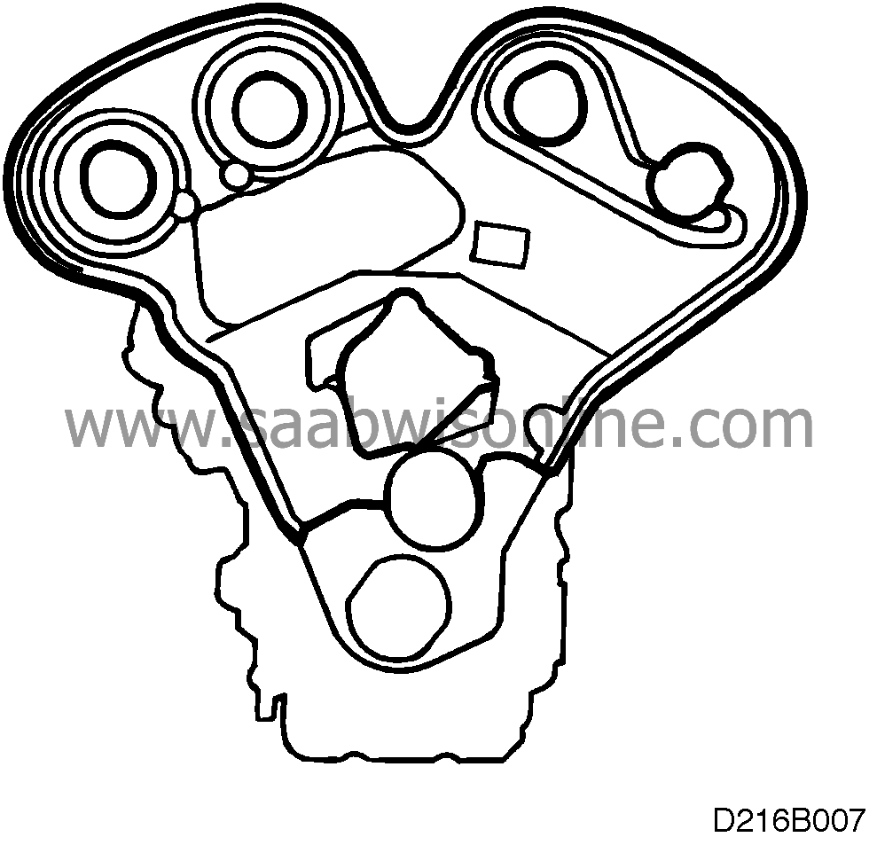
Remove the inner timing cover.
|
|
15.
|
Place the new timing cover in position, apply locking fluid 74 96 268 to the bolts,
and fit and tighten the bolts.
|
|
16.
|
Clean the flanges on the water pump and block, and fit a new ’O’
ring.
|
|
17.
|
Smear non-acidic petroleum jelly over the flanges and ’O’ ring,
and fit the water pump.
|
|
18.
|
Fit the camshaft pinions. Check that the timing marks line up with those on the
timing cover. Immobilize the pinions using tools KM-800-1 and KM-800-2, and tighten the
bolts.
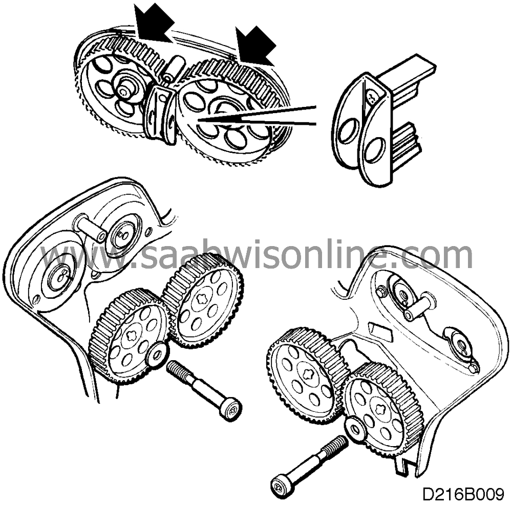
Tightening torque: 50 Nm (37 lbf ft + 60°).
|
|
19.
|
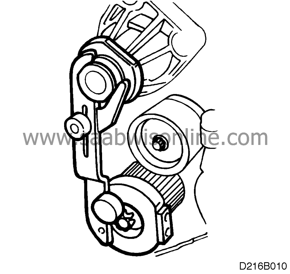
Fit the new belt-tensioner arm.
Tightening torque: 40 Nm (30 lbf ft)
|
|
20.
|
Rotate the crankshaft to just short of the 0° mark and fit tool KM-800-10 to
the shaft. Rotate the shaft carefully (in the engine’s direction of rotation) until the arm is
touching the water-pump flange. Remove the tool.
|
|
21.
|
Place the belt in position (arrows pointing in direction of rotation), making sure
that the marks on the belt line up with those on crankshaft’s cam belt pinion and the
camshaft pinions. Using tool KM-800-30 to hold the belt in place, adjust the tensioner wheel
by hand (anticlockwise), to prevent the belt from slipping out of mesh.
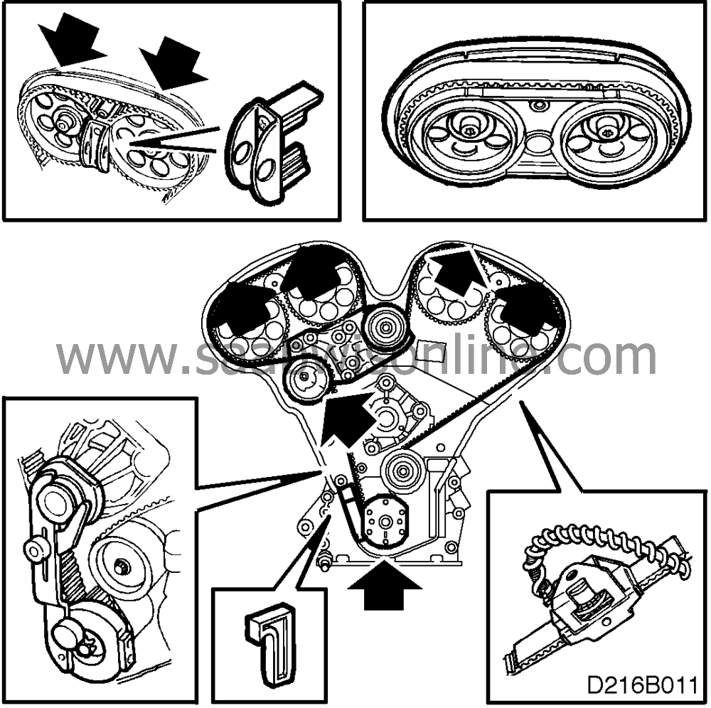
Fit tool KM-800-10, place part of the belt over it and use tool 83 93 985 to measure the
belt tension.
Secure the idler wheel centre bolts, leaving them finger-tight. Turn the lower idler wheel
anticlockwise, until a belt tension of 275-300 Nm is reached. Tighten the centre bolt to the
specified torque.
Tightening torque: 40 Nm (30 lbf ft)
|
Important
|
|
This adjustment of the belt tension is only a
measure and
be used as a reference value after final adjustment of the
belt.
|
|
|
|
|
22.
|
Using an Allen key, adjust the two idler wheels to bring the two marks into line.
Re-tighten.
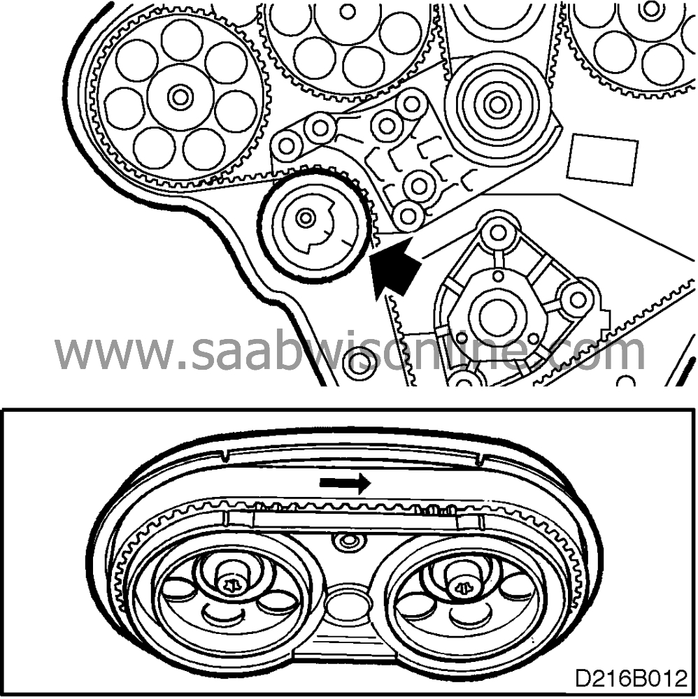
Tightening torque: 20 Nm (15 lbf ft).
Remove the immobilizer tool for No. 1 and 2 camshaft pinions and fit tool KM-800-20.
Turn the top idler wheel anticlockwise until the No. 2 pinion has moved 1-2 mm
clockwise.
Tightening torque: 40 Nm (30 lbf ft)
Remove the other immobilizer tools.
|
|
23.
|
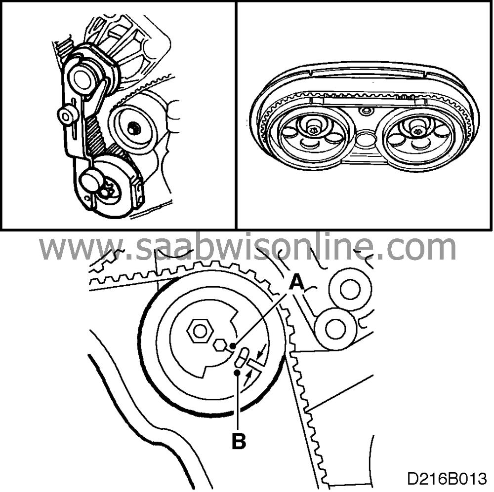
Turn the crankshaft two revolutions, to just before the ’0’ mark,
and fit the immobilizer tool on the shaft. Turn the crankshaft carefully in the engine’s
direction of rotation until the arm touches the water-pump flange. Tighten the arm. Fit tool KM-
800-20 onto the camshaft pinions and check that the markings on the pinions are in line with
those on the tool, and that the edge of the belt is in line with the pinion edges.
|
Important
|
|
Check that mark (A) is approximately 2 mm above mark (B), as shown. If the distance
between the marks is less than this, the adjustment will have to be carried out
again.
|
|
|
|
|
24.
|
Fit the crankshaft pulley with the recess facing the projection on the block
(diagonally upwards and towards the front).
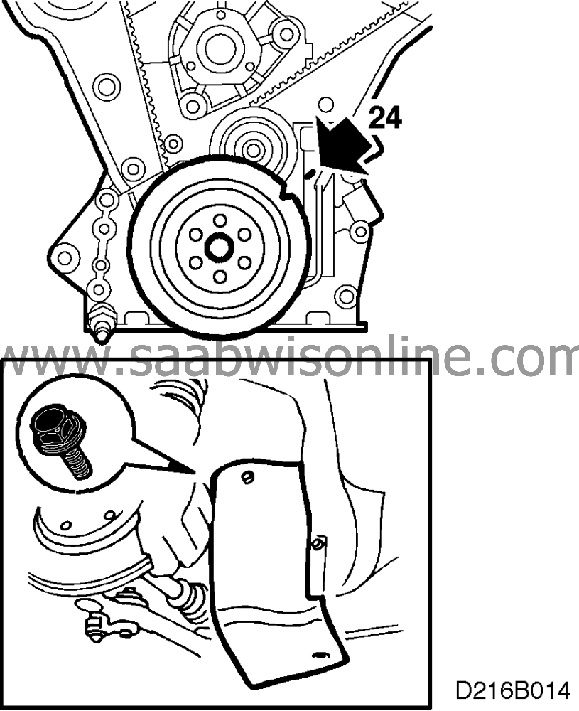
Tightening torque: 20 Nm (15 lbf ft).
|
|
25.
|
Refit the wheel-arch liner and the front wheel.
Tightening torque,
Steel wheel: 100 Nm (74 lbf ft)
Alloy wheel: 120 Nm (89 lbf ft).
Lower the car.
|
|
26.
|
Fit the outer timing cover.
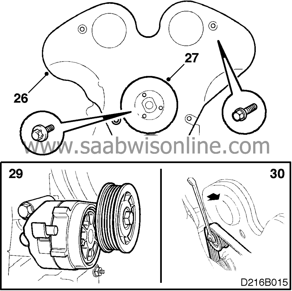
|
|
27.
|
Fit the water-pump pulley (lever the engine towards the LH side of the car, using
the engine-mounting bracket for purchase). Apply locking fluid 74 96 268 to the pulley bolts
and tighten to the specified torque.
Tightening torque: 10 Nm (7.5 lbf ft)
|
|
28.
|
Fit the steering servo pulley.
Tightening torque: 8 Nm (6 lbf ft)
|
|
29.
|
Fit the belt tensioner.
Tightening torque: 40 Nm (30 lbf ft)
|
|
30.
|
Using a 15-mm socket, turn the belt tensioner bolts towards the front of the car
to slacken the tension in the belt. Ease the belt onto the water-pump pulley and check its
seating on the other pulleys. Gently release the belt tensioner.
|
|
31.
|
Tighten the pulley bolts.
|
|
32.
|
Fit the air cleaner complete with hoses.
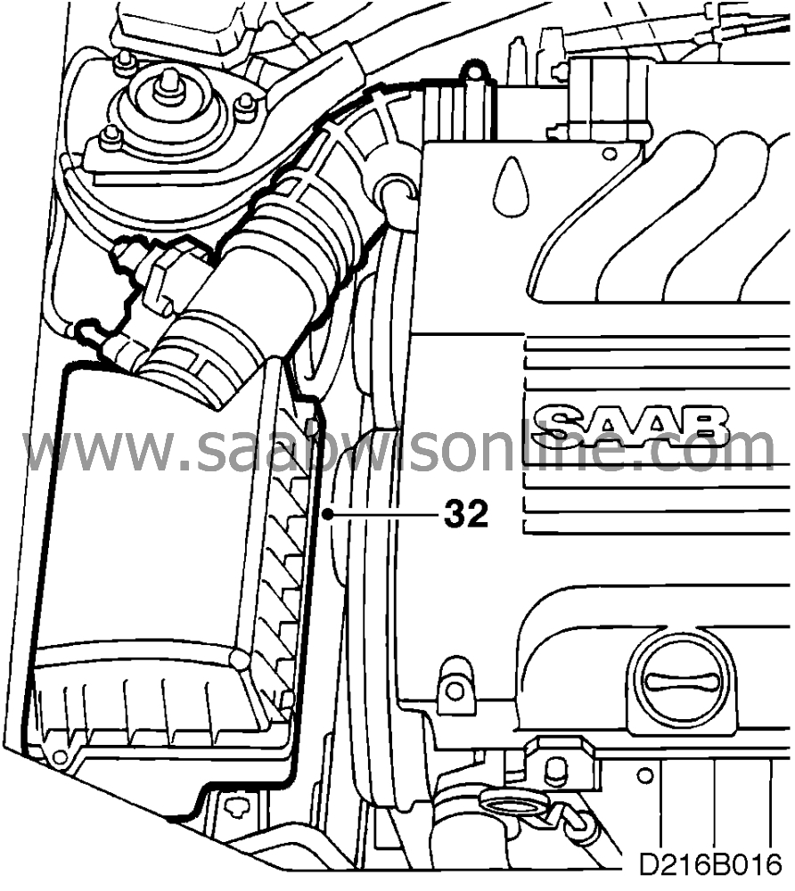
|
|
33.
|
Check that the radiator drain plug is fitted and tightened, recharge the system
with coolant and check for leaks.
|
|
34.
|
Bleed the system as follows.
Add coolant up to the MAX mark, fit the cap and start the engine. Run the engine,
ideally pumping the throttle from time to time, until the fan cuts in.
Remove the filler cap and refill up to the MAX mark.
Fit the cap and run the engine, ideally pumping the throttle from time to time, until the
fan has cut in at least three more times.
Switch off the engine and, if necessary, add coolant to bring the level up to the MAX
mark again.
|
|
Marking the campaign plate
|
After completion of the work, box B2 on the campaign plate must be marked. If
the work has been done by the importer, mark the box with a ’7’ or, if by a
dealer, with an ’8’.
See separate literature.


