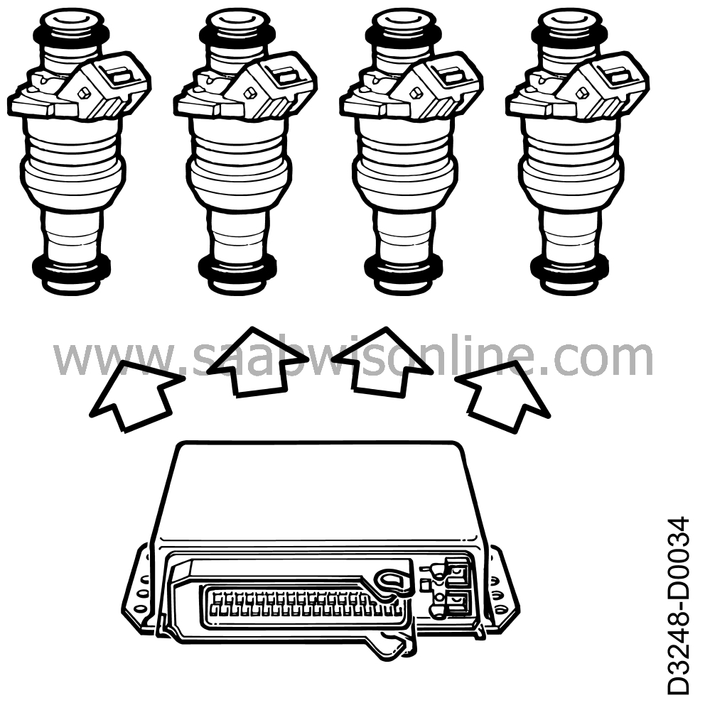
Principle of operation, fuel injection
| Principle of operation, fuel injection |

| Injectors |
The injectors are of solenoid type with needle and seat. They open when current flows through the coil and are closed by a powerful spring when the current is cut off.
For optimal combustion and so cleaner exhaust gases, the spray nozzles have four holes to ensure good distribution of the fuel.
The jets of fuel are set within extremely tight limits, each jet individually and between the two jets (one jet for each inlet valve). This also makes big demands on the positions of the injectors and to ensure their precise location they are fixed in pairs on special mounting brackets between 1-2 and 3-4.
All the injectors receive operating current from the main relay while the control module grounds them individually as follows.
| • |
Injector 1 is grounded via pin 17
|
|
| • |
Injector 2 is grounded via pin 34
|
|
| • |
Injector 3 is grounded via pin 16
|
|
| • |
Injector 4 is grounded via pin 35
|
|
On the basis of the control module's input signals from the oxygen sensor, mass air flow sensor, crankshaft position sensor and other sensors, the exact amount of fuel to be injected into the cylinder is calculated. This is done by varying the length of the grounding signals between 3 and 15 ms. In conditions of extreme cold, i.e. below -30°C (-22°F) signal duration may increase to 220 ms. The system has no cold-starting valve.
While the starter motor turns the engine over and at temperatures below 20°C (68°F), the control module sends signals to all the injectors simultaneously to facilitate starting (only during the first injection of fuel).
During engine braking, all injectors close to reduce the amount of HC (fuel shut-off).
| Fuel consumption |
The signal to the instrument indicating fuel consumption is not a separate output signal from the control module. Instead, the signal is obtained from pin 16 of the control module. This signal is also sent to injector No. 3.


