P1680
Symptom: CHECK ENGINE lamp (MIL) on.
Secondary air injection relay or A/C relay
Fault symptoms
CHECK ENGINE lamp (MIL) on.
Conditions
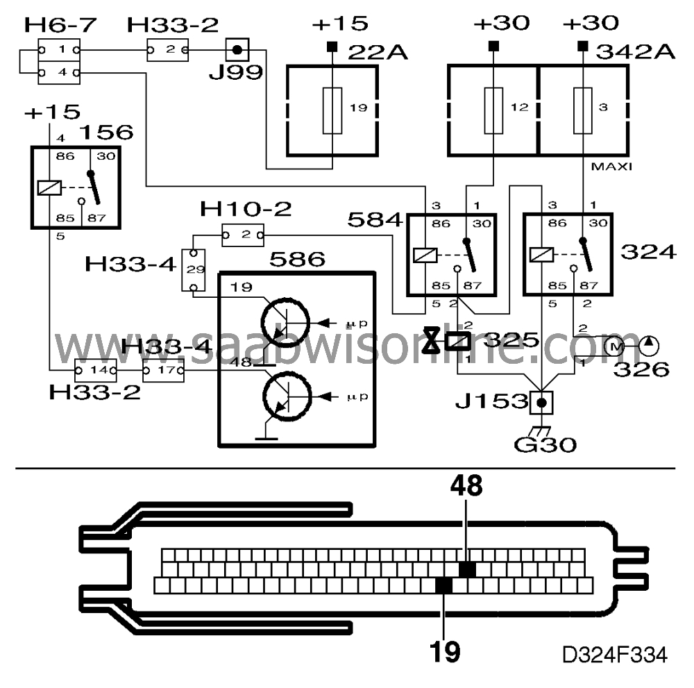
One of the control module's integrated circuit output stages is used for checking
the secondary air injection relay and A/C relay. Should a fault, open circuit or short circuit to
ground or battery positive (B+) occur, diagnostic trouble code P1680 will be
generated.
Diagnostic help
The relay for controlling secondary air injection can be activated with the ISAT scan
tool.
|
-
|
Select "SECOND. AIR RELAY".
|
The relay (and secondary air injection) is activated at a frequency of 0.5 Hz for
30 seconds.
The relay for controlling the A/C can be activated with the ISAT scan tool.
The relay (and the compressor) is activated at a frequency of 0.5 Hz for 30
seconds.
Check the wiring
Intermittent faults may occur as a result of temporary short circuits and breaks in the
wiring. Jiggle the wiring at several points and in different directions to ascertain whether the
wiring harness, including any connectors, is causing the trouble. Observe the multimeter,
ISAT scan tool or test lamp while doing this.
Diagnostic procedure
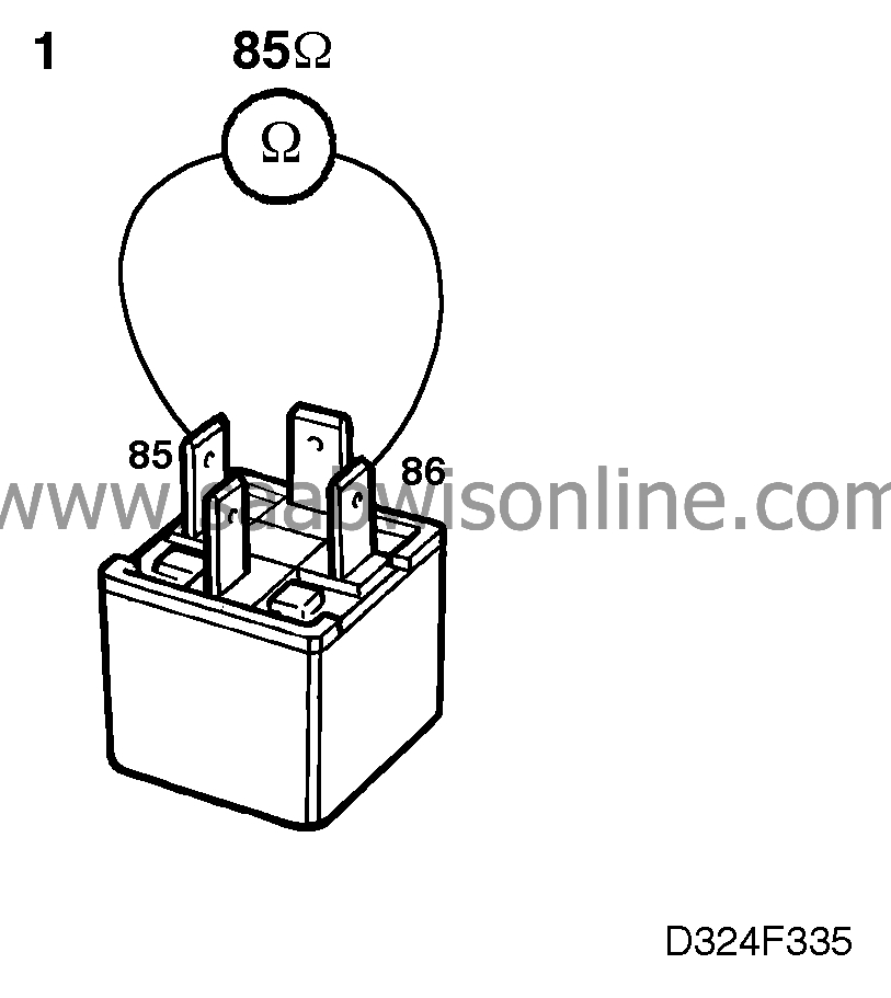
1. Check the resistance of the secondary air injection relay
|
-
|
Remove the secondary air injection
relay. (Relay 584 is located in the main fuse box in the engine bay.)
|
|
-
|
Check the resistance of the relay,
taking a reading (in ohms) across:
|
Is the resistance reading OK?
Continue with point 2.
Change the relay. Continue with point
7.
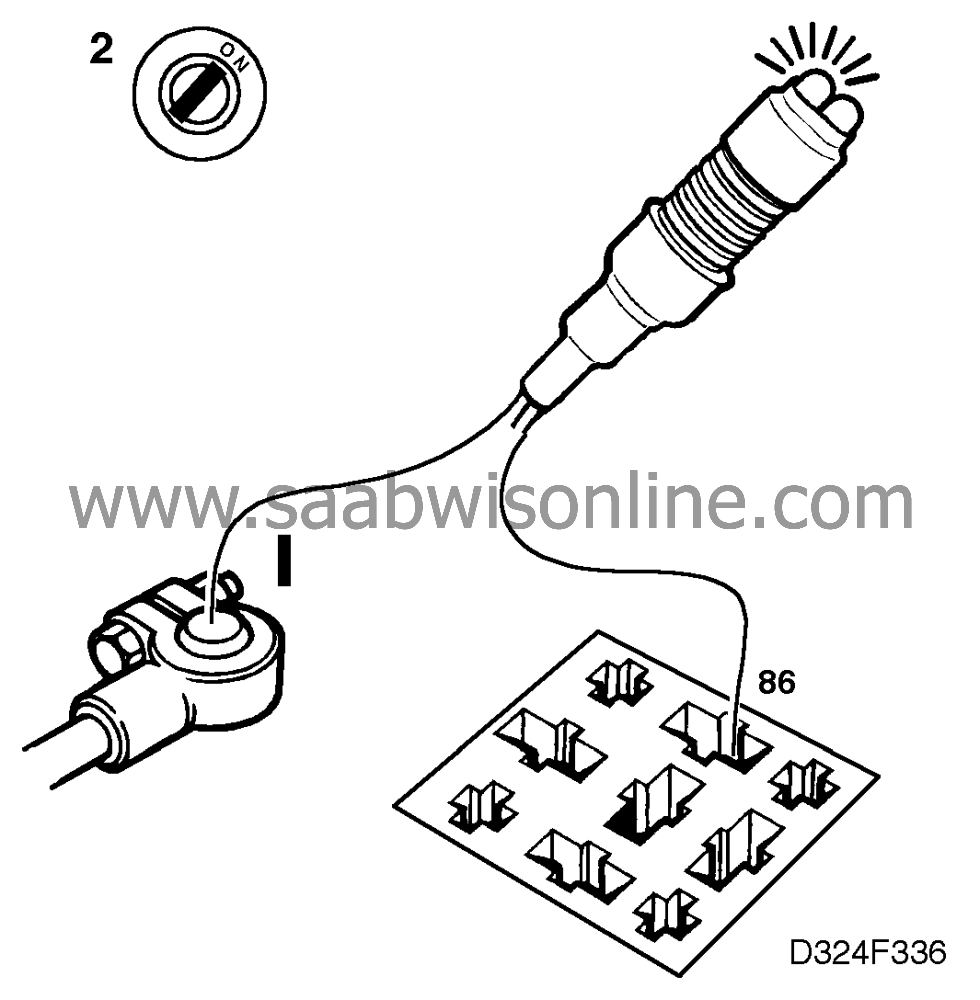
2. Check the secondary air injection relay's power
supply
|
-
|
Connect the test lamp
to:
|
|
-
|
Turn the ignition switch to the ON position.
|
The test lamp should light up.
Did the test lamp light up?
Continue with point 3.
Check and if necessary repair or replace the wiring, including connectors,
between pin 86 of the relay socket and the power supply (+15 circuit). Continue with point
7.
3. Check the secondary air injection relay's ground
connection
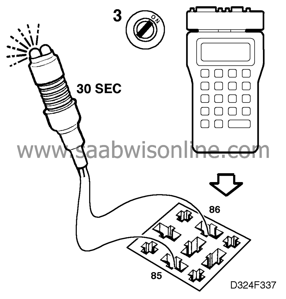
The relay is connected to ground via pin 19 of the control module.
|
-
|
Connect the test lamp to the relay
socket between:
|
|
-
|
Connect the ISAT Scan Tool.
|
|
-
|
Turn the ignition switch to the ON position.
|
|
-
|
Select "SECOND. AIR RELAY".
|
The test lamp should flash.
Test lamp flashing?
Continue with point 4.
The test lamp does not light up at all or is on continuously. Check and if
necessary repair or replace the wiring between pin 10 of the control module and pin 85 of the
relay socket. Continue with point 7.
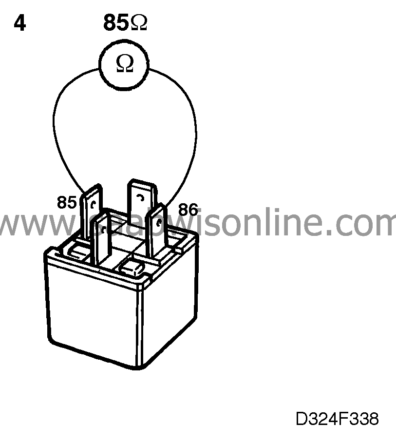
4. Check the resistance of the A/C relay
|
-
|
Unplug the A/C relay (located in the
main fuse box in the engine bay).
|
|
-
|
Check the resistance of the relay,
taking a reading (in ohms) across:
|
Is the resistance reading OK?
Continue with point 5.
Change the relay. Continue with point 7.
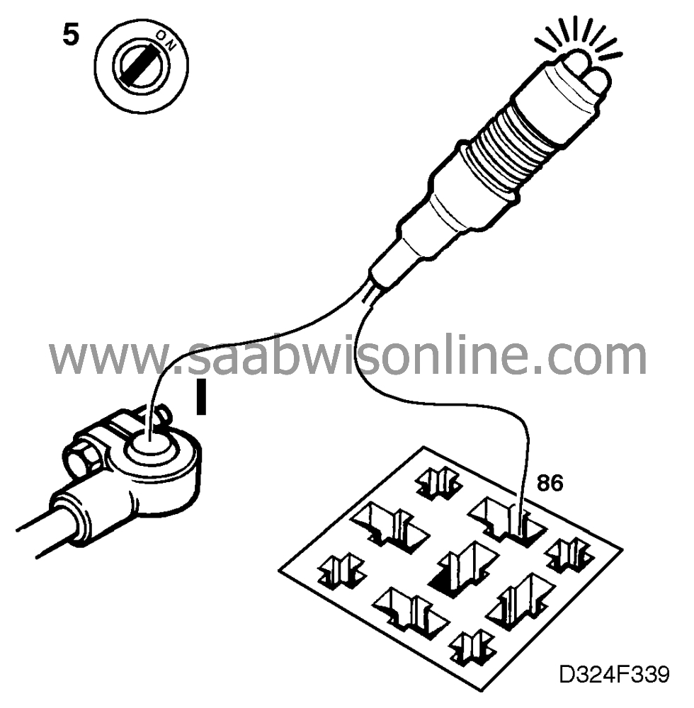
5. Check the A/C relay's power supply
|
-
|
Connect the test lamp
to:
|
|
-
|
Turn the ignition switch to the ON position.
|
The test lamp should light up.
Did the test lamp light up?
Continue with point 6.
Check and if necessary repair or replace the wiring, including connectors,
between pin 86 of the relay socket and the power supply (+15 circuit). Continue with point
7.
6. Check the A/C relay's ground
connection
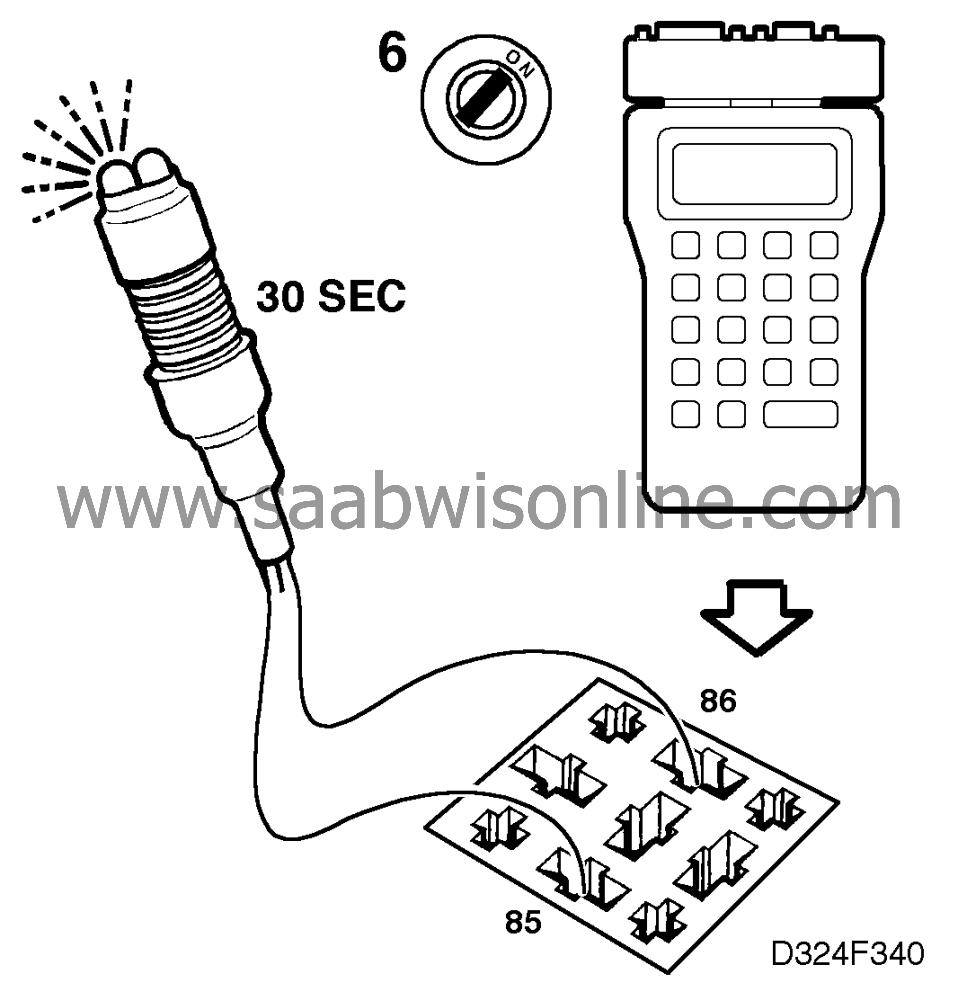
The relay is connected to ground via pin 48 of the control module.
|
-
|
Connect the test lamp to the relay
socket between:
|
|
-
|
Connect the ISAT Scan Tool.
|
|
-
|
Turn the ignition switch to the ON position.
|
The test lamp should flash.
Test lamp flashing?
Continue with point 7.
The test lamp does not light up at all or is on continuously. Check and if
necessary repair or replace the wiring between pin 48 of the control module and pin 85 of the
relay socket. Continue with point 7.
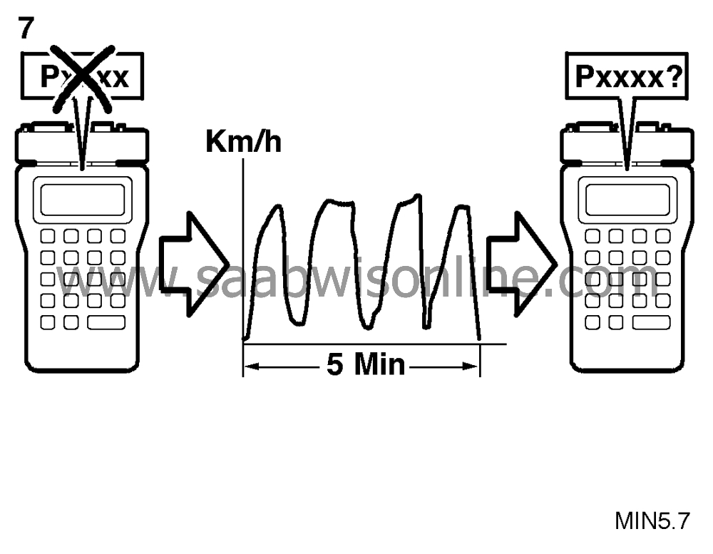
7. Final check
|
-
|
Clear the diagnostic trouble
code.
|
|
-
|
Implementation of driving
cycle:
|
|
-
|
Evaluation of driving cycle:
|
Has the diagnostic trouble code recurred?
Continue as described in
 .
.
The steps taken to rectify the fault were
correct.


